Note: Descriptions are shown in the official language in which they were submitted.
CA 02856206 2014-05-09
WO 2013/074358
PCT/US2012/064030
POWER CONVERTER BASED ON H-BRIDGES
BACKGROUND
[0001] The
subject matter of this disclosure relates generally to power converters,
and more particularly to power converter topologies based on H-bridges that
are coupled
to one or more multi-phase electromagnetic energy conversion devices (EMECDs),
including without limitation, multi-phase transformers with open windings
and/or electric
machines with open windings, to provide a regenerative or partial regenerative
power
converter.
[0002] Power
converter cell topologies associated with variable frequency drive
(VFD) applications continue to receive attention. New power converter cell
topologies are
continually being introduced. Some known power converter cell topologies have
employed
H-bridge converters and/or H-bridge inverters.
[0003] Some of
the foregoing power cells, when connected to a load, such as a
motor, can provide power from an input source to a motor when operating in the
motoring
mode. Such a power cell may sometimes be referred to as a unidirectional or
two-quadrant
(2Q) cell. This is because when the four quadrants of speed and torque are
considered, the
operating characteristics of the cell are such that it operates in either the
quadrant where both
speed and torque are positive (first quadrant) or the quadrant where both
speed and torque
are negative (third quadrant).
[0004] When
motor speed need to be reduced however, power from the motor needs
to be absorbed by the power converter cell. This mode of operation is
generally referred to as
the regeneration mode. In such operating modes, regenerative or four-quadrant
cells are
required.
[0005] A
regenerative converter may include a three level output power
conversion stage. The output power stage generally includes electrical
switches such as
IGBTs (Insulated Gate Bipolar Transistors). Other useful switches include GTOs
(Gate
Turn Off Thyristors), IGCTs (Integrated Gate Commutated Thyristors), IEGTs
(Injection Enhanced Gate Transistors) and MOSFETs (Metal Oxide Semiconductor
1
CA 02856206 2014-05-09
WO 2013/074358
PCT/US2012/064030
Field Effect Transistors). The switches may be paired with anti-parallel
freewheeling
diodes to accommodate, for example, inductive motor load currents. A
controller is
generally used for controlling each of the switches. The controller may
comprise, for
example, a computer and/or a digital signal processor.
[0006] Known
regenerative power converter topologies comprising H-bridges
continue to struggle with size, cost and reliability constraints due to the
high number of
active switches required to provide a workable topology. In view of the
foregoing, there
is a need to provide a regenerative power converter cell structure that
requires fewer
active switches to provide a workable topology having fewer components, higher
reliability, less cost, and that has a smaller physical size than known
regenerative power
converter cell topologies.
2
CA 02856206 2014-05-09
WO 2013/074358
PCT/US2012/064030
BRIEF DESCRIPTION
[0007] An exemplary embodiment of a power converter comprises:
a first section comprising a plurality of H-bridge converters;
a second section comprising a plurality of H-bridge inverters, wherein
each H-bridge inverter is coupled by a corresponding dc link stage to a
corresponding
H-bridge converter such that each dc link stage is isolated from every other
dc link
stage; and
a multi-phase electro-magnetic energy conversion device (EMECD)
comprising open windings that are connected to the power converters to provide
a
regenerative power converter.
[0008] Another embodiment of a power converter comprises:
a first section comprising a plurality of H-bridge converters;
a second section comprising a plurality of H-bridge inverters, wherein
each H-bridge inverter is coupled via a corresponding dc link stage to a
corresponding
H-bridge converter such that each dc-link stage is isolated from every other
dc-link
stage; and
a multi-phase electro-magnetic energy conversion device (EMECD)
with open windings, wherein the open windings are connected to only the H-
bridge
inverters to provide a regenerative power converter.
[0009] According to yet another embodiment, a power converter comprises:
a first section comprising at least one three-phase input conversion
stage;
a second section comprising a plurality of H-bridge inverters coupled to
the first section by a single common dc link; and
3
CA 02856206 2014-05-09
WO 2013/074358
PCT/US2012/064030
a multi-phase electro-magnetic energy conversion device (EMECD)
comprising open windings that are connected to only the H-bridge inverters to
provide
a regenerative power converter.
[0010] According to still another embodiment, a power converter comprises:
a first section comprising a plurality of H-bridge converters;
a second section comprising a plurality of H-bridge inverters, wherein
first section is coupled by a single common dc link stage to the second
section;
a first multi-phase electro-magnetic conversion device (EMECD)
comprising open windings that are connected to only the H-bridge converters;
and
a second multi-phase EMECD comprising open windings that are
connected to only the H-bridge inverters to provide a regenerative power
converter.
4
CA 02856206 2014-05-09
WO 2013/074358
PCT/US2012/064030
DRAWINGS
[0011] The
foregoing and other features, aspects and advantages of the invention
are apparent from the following detailed description taken in conjunction with
the
accompanying drawings in which like characters represent like parts throughout
the
drawings, wherein:
[0012] Figure
1 is a simplified diagram illustrating a regenerative power
converter cell topology that is known in the art;
[0013] Figure
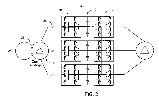
2 illustrates a regenerative converter according to one embodiment;
[0014] Figure
3 illustrates a regenerative converter according to another
embodiment;
[0015] Figure
4 illustrates a regenerative converter according to one embodiment;
[0016] Figure
5 illustrates a regenerative converter according to another
embodiment;
[0017] Figure
6 illustrates a regenerative converter according to yet another
embodiment; and
[0018] Figure
7 illustrates a partially regenerative converter according to still
another embodiment.
[0019] While
the above-identified drawing figures set forth alternative
embodiments, other embodiments of the present invention are also contemplated,
as
noted in the discussion. In all cases, this disclosure presents illustrated
embodiments of
the present invention by way of representation and not limitation. Numerous
other
modifications and embodiments can be devised by those skilled in the art which
fall
within the scope and spirit of the principles of this invention.
CA 02856206 2014-05-09
WO 2013/074358
PCT/US2012/064030
DETAILED DESCRIPTION
[0020] Figure
1 is a simplified diagram illustrating a regenerative converter
topology 10 that is known in the art. It can be seen that the converter 10
employs a high
parts count active front end (AFE) converter 12 per phase since it requires
the use of 9
phase connections 14 and converter phase-legs in the converter 12 to connect
with one or
more conventional three-phase transformers 16. The drawing figures throughout
have
been simplified with small hashes crossing single line connections for ease of
understanding. These small hashes are used to indicate the number of real
connection
wires which are represented by the single line diagrams.
[0021] The
converter 10 can be seen to also employ a plurality of H-bridge
inverters 18 that are each coupled to a corresponding AFE converter 12 via a
corresponding dc-link 19. One output of each H-bridge inverter 18 of the three
phases is
generally connected to a corresponding output of each other H-bridge inverter
18. Each
other H-bridge inverter output is then connected to its corresponding machine
phase.
Thus, each dc-link 19 must be isolated from every other dc-link 19 to avoid a
short circuit
condition.
[0022] Since
the dc-links 19 are (indirectly) already connected via the output H-
bridge inverters 18 on the output side 20, the same approach using H-bridges
on the grid
side 22 cannot be used. The present inventors recognized that a three-phase
transformer
with isolated secondary phase windings (open windings) could be employed along
with
H-bridge converters on the input (grid) side of a converter such as described
herein with
reference to Figure 2, to isolate each dc-link from every other dc-link and
avoid a short
circuit condition. It can thus be appreciated that the three-phases can be
connected
together in only one or none of the converter sections 12, 18 or 19.
[0023] Figure
2 illustrates a regenerative converter 30 according to one
embodiment. The converter 30 topology is advantageous in that it allows use of
a regular
machine connection. Converter 30 can be seen to employ a plurality of active H-
bridge
converters 32. Each H-bridge converter 32 is coupled to a corresponding H-
bridge
inverter 18 via a corresponding dc-link 19. The converter 30 H-bridge
converters 32 are
6
CA 02856206 2014-05-09
WO 2013/074358
PCT/US2012/064030
each also coupled to a corresponding pair of open secondary winding
connections 34 of a
three-phase transformer 36 with open (isolated) secondary windings 38. The
converter
30 advantageously requires fewer active components in the active front end as
well as
fewer connections connecting the grid transformer 36 to the active front end
of the
converter 30.
[0024] Depending on the design of the transformer 36, a certain degree of
freedom arises for the grid side H-bridge control. Specifically, when the
primary side of
the transformer 36 is delta connected, a common mode current can be injected
in the H-
bridge phase currents without affecting the grid. When the primary of the
transformer is
star connected, a common mode voltage can be injected in the H-bridge phase
voltages
without affecting the grid. Both degrees of freedom can be utilized to control
the power
balance between the phases, e.g. for reducing the dc-link voltage ripple or
for removing
long term drifts.
[0025] Figure 3 illustrates a regenerative converter 40 according to
another
embodiment. The converter 40 topology is similar to the converter 30 topology,
except
the converter 40 employs a machine 42 with open windings on the machine side
of the
converter 40. Machine 42 provides the required isolation between the dc-links
19 to
avoid a short circuit condition that would otherwise be caused by connecting a
conventional three-phase transformer 44 to the H-bridge converters 32. The H-
bridge
converters 32 are configured to provide the input conversion stage for the
active front end
of the regenerative converter 40.
[0026] Figure 4 illustrates a regenerative converter 50 according to one
embodiment. The converter 50 comprises a three-phase input conversion stage 12
that is
coupled at its input to three phases of a conventional three-phase transformer
44
secondary winding, and at its output to a common dc-link 52. The common dc-
link 52
couples the three-phase input conversion stage 12 to three H-bridge inverters
18 that are
connected at their outputs to a three-phase machine with open windings 42 on
the
machine side of the converter 50.
7
CA 02856206 2014-05-09
WO 2013/074358
PCT/US2012/064030
[0027] Figure
5 illustrates a regenerative converter 60 according to another
embodiment. The converter 60 includes an active front end (AFE) comprising
three H-
bridge converters 32 that is coupled at its input to six phase terminals 34 of
a three-phase
transformer 36 with open secondary windings 38, and at its output to a common
dc-link
52. The common dc-link 52 couples the three H-bridge converters 32 to an H-
bridge
inverter stage comprising three H-bridge inverters 18 that are connected at
their outputs
to a three-phase machine with open windings 42 on the machine side of the
converter 60.
[0028] Figure
6 illustrates a regenerative converter 70 according to yet another
embodiment. The converter 70 includes an active front end comprising a
plurality of
three-phase input conversion stages 12. Each input conversion stage 12 is
coupled at its
input/grid side to three secondary winding phases of a corresponding
conventional three-
phase transformer 16, and at its output to a common dc-link 52. The common dc-
link 52
couples the plurality of three-level input conversion stages 12 to a plurality
of H-bridge
inverters 18 that are connected at their outputs to a three-phase machine with
open
windings 42 on the output/machine side of the converter 70.
[0029] Figure
7 illustrates a partially regenerative converter 80 according to still
another embodiment. The converter 80 includes an active front end comprising a
three-
phase input conversion section 12 and a pair of diode rectifier converter
sections 82.
Each section 12, 82 of the active front end is coupled at its input/grid side
to three
secondary winding phases of a corresponding conventional three-phase
transformer 84,
and at its output to a common dc-link 52. The common dc-link 52 couples each
section
of the active front end to a plurality of H-bridge inverters 18 that are
connected at their
outputs to a three-phase machine with open windings 42 on the output/machine
side of
the converter 80.
[0030] In
summary explanation, various converter topologies have been
described. A preferred embodiment comprises a three phases to three-phase,
active front
end converter topology based on three-level neutral point clamped H-bridges,
and an
inversion stage for each of the three phases. According to one embodiment, the
output
voltage is synthesized using a plurality, e.g. five, independent voltage
levels in order to
8
CA 02856206 2014-05-09
WO 2013/074358
PCT/US2012/064030
generate the desired sinusoidal waveform. The desired voltage levels can be
generated
by a local controller for each H-bridge inverter or set of H-bridge inverters,
such as
depicted in Figure 2. The local controllers can be themselves controlled from
a central
controller, such as also depicted in Figure 2. Each dc link of the phase
bridges are
isolated between each other, as stated herein. According to one aspect, a
transformer
with open (isolated) secondary windings may be used at the input which
provides a
simpler topology than other known regenerative converter topologies using H-
bridges. A
regenerative converter topology using the principles described herein provides
four
quadrant operations for the output voltages and currents, and advantageously
employs up
to or less than two-thirds the number of active front end components than the
closest
know topology of its kind. Further, some embodiments of active power flow
control
across each of the isolated dc links can reduce the required number of dc link
capacitors.
[0031] While
only certain features of the invention have been illustrated and
described herein, many modifications and changes will occur to those skilled
in the art.
Those skilled in the power converter art for example, will readily appreciate
the various
transformer primary winding and secondary winding configurations illustrated
herein are
merely exemplary, and other numbers and configurations of secondary windings
are possible. It
is, therefore, to be understood that the appended claims are intended to cover
all such
modifications and changes as fall within the true spirit of the invention.
[0032] The
drawings, for example, illustrate a 3-Level Neutral Point Clamped
(NPC) topology utilized in three-phase bridges and the H-bridges. However, the
principles described herein can also be applied using 2-level phase legs or
another multi-
level topology to build the three-phase bridges or the H-bridges. Further,
although the
drawings show only a single H-bridge per phase on each side, the principles
described
herein can also be applied for multiple H-bridges per side and phase. Although
topologies are shown for three-phase systems, they can easily be applied for
other multi-
phase systems. Embodiments that show a standard transformer on the grid-side
can also
work without transformer when the grid voltage is matching the converter
voltage rating.
9