Note: Descriptions are shown in the official language in which they were submitted.
CA 02856750 2014-05-23
WO 2013/082815 PCT/CN2011/083782
1
FLUID DISPENSING SHAVING RAZOR
FIELD OF THE INVENTION
The present invention relates to personal-care appliances in general, and more
particularly,
to fluid dispensing shaving razors having a replaceable fluid dispensing
cartridge for shaving and
dispersing fluid to a surface of the skin and/or hair.
BACKGROUND OF THE INVENTION
Skin care can be of particular importance in improving or enhancing the
appearance of
men and women. Various products and methods can be used to care for skin. For
example,
exfoliant scrubs, cleansers, and lotions are sometimes used to maintain
healthy-looking skin.
Exfoliant scrubs can be used to remove dead skin cells from the surface of the
skin, which can
give the skin an improved tone. Soaps and other cleansers can be used to
remove dirt and excess
oil from the skin, which can help prevent clogging of pores. Consequently,
acne and other types
of skin blemishes can be prevented in some cases. Lotions and various other
topical ointments
can also be used to deliver nutrients and/or moisturizers to the skin in an
effort to improve the
appearance and/or the health of the skin. Other types of cosmetic products
(e.g., creams and
lotions) or drug actives are sometimes used in an attempt to eliminate
wrinkling and other signs
of aging.
The shaving process typically includes the application of a shaving aid
material (e.g.,
shaving cream) to the surface and the separate step of shaving the hair using
a razor assembly.
The shaving aid material oftentimes includes at least one suitable agent
(e.g., a lubricating agent,
a drag-reducing agent, a depilatory agent, etc.) that enhances the shaving
process. Most
consumers find this type of preparation to be rather inconvenient because of
the need for multiple
shaving products, e.g., a wet shaving razor and a skin preparation product, as
well as the
undesirable necessity for multiple application steps during the wet shaving
process. Furthermore,
this process can be messy and requires the consumer rinse their hands after
applying the shave
gel. This multi-step process also results in an overall extended shaving
experience which most
consumers do not prefer given typical morning hygiene routines. It may,
however, be desirable to
apply liquids of other kinds to the skin before, during, or after shaving. It
has been found that
especially in the case of males who shave facial hair, it is important to
provide a shave
preparation of some sort prior to shaving in order to adequately hydrate the
coarser facial hairs to
allow for an easier and closer shave. It has been suggested in the literature
to provide a shaving
razor with a built in dispensing unit that releases a fluid (e.g., shaving
aid) from a fluid container.
However, these razors do not provide for simple and intuitive replacement
and/or loading of a
fluid dispensing cartridge.
CA 02856750 2014-05-23
WO 2013/082815 PCT/CN2011/083782
2
SUMMARY OF THE INVENTION
In one aspect, the invention features, in general, a fluid dispensing shaving
razor having a
fluid interconnect member with a fluid port extending from a base member at a
first end. A
cartridge housing is mounted to the fluid interconnect member. A fluid
applicator is mounted to
a second end of the fluid interconnect member. A handle has a first end with a
resilient member
defining an opening. The fluid port is releasably engaged within the opening
of the resilient
member.
The details of one or more embodiments of the invention are set forth in the
accompanying drawings and the description below. It is understood that certain
embodiments
may combine elements or components of the invention which are disclosed in
general, but not
expressly exemplified or claimed in combination, unless otherwise stated
herein. Other features
and advantages of the invention will be apparent from the description and
drawings, and from the
claims.
BRIEF DESCRIPTION OF THE DRAWINGS
Figure 1 is a front view of one possible embodiment of a personal-care
appliance.
Figure 2 is a rear view of possible embodiment of a fluid dispensing cartridge
that may be
incorporated into the personal-care appliance of Fig. 1
Figure 3 is a front assembly view of the personal-care appliance of Fig. 1.
Figure 4 is a partial front view of the personal-care appliance of Fig. 1.
Figure 5 is a partial front view of the personal-care appliance of Fig. 1.
Figure 6 is an assembly view of the fluid dispensing cartridge of Fig. 2.
Figure 7 is a cross section view of the personal-care appliance, taken
generally along the
line 7-7 of Fig. 1.
Figure 8 is a cross section view of the fluid dispensing cartridge, taken
generally along
the line 8-8 of Fig. 6.
DETAILED DESCRIPTION OF THE INVENTION
The present disclosure is not limited to wet shaving razors, or even razors in
general. It is
understood that certain aspects of the present disclosure may also be used for
dry electric shaving
razors that have one or more rotating or reciprocating blades or other
personal care appliances
(e.g., toothbrushes, depilatory applicators, epilators, or other beauty
applicators). Furthermore, it
is understood that certain aspects of the present disclosure may be used
independently for
applying a fluid.
CA 02856750 2016-10-11
3
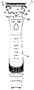
Referring to Fig. I, one possible embodiment of the present disclosure is
shown illustrating a
front view of a personal-care appliance 10. For example, the personal-care
appliance may be a fluid
dispensing razor (as shown), a toothbrush, a mascara brush, or any other
personal-care appliance that
dispenses a fluid. As will be described in greater detail below, the personal-
care appliance 10 may
include a handle 20 configured to receive a pump assembly (not shown) and a
fluid reservoir (not
shown). The handle 20 may have a cover 22 that protects and/or conceals the
pump and/or fluid
reservoir within the handle 20. The cover 22 may be mounted to the handle 20
and removably
secured in place (e.g., snap fit to the handle 20).
A fluid dispensing cartridge 50 may be removably mounted to the handle 20
(i.e.,
replaceable). The fluid dispensing cartridge 50 may include fluid interconnect
member 52 having a
cartridge housing 54 pivotably mounted to one end of the fluid interconnect
member 52. An
opposing end of the fluid interconnect member 52 may be removably mounted to
one end of the
handle 20. The cartridge housing 54 may have a cap 56, a guard 58 in front of
the cap 56, and one or
more blades 60 between the cap 56 and the guard 58. The fluid dispensing
cartridge 50 may include
a fluid applicator 62 for delivering one or more fluids to a surface to be
treated (e.g., shaved). One
end of the fluid applicator 62 may be mounted to the cartridge housing 54. For
example, the fluid
applicator 62 may include a guard 64 mounted to thc cartridge housing 54
(e.g., the guard 58) to
apply and spread the fluid to the surface to be treated (e.g., skin or hair)
during a stroke of the
personal-care appliance 10 against the skin. An opposing end of the fluid
applicator 62 may be
mounted to the fluid interconnect member 52. In one embodiment, the fluid
applicator 62 is mounted
to a second end of the fluid interconnect member 52 and extends outside the
cartridge housing 54 in
front of said guard 58 of the cartridge housing 54.
Referring to Fig. 2, a rear view of the fluid dispensing cartridge 50 is
shown. The fluid
interconnect member 52 may have a base member 100 with a wall 102 defines a
cavity 104. The
cavity 104 may be dimensioned to receive a portion of the handle 20 (not
shown). In certain
embodiments, the cavity 104 may be non-symmetrical to facilitate one-way
mounting of the fluid
dispensing cartridge 50 to the handle 20 (not shown). For example, the cavity
104 may be generally
"D" shaped. The wall 102 may define one or more engagement surfaces 106 and
108 (e.g., a recesses
or a protrusion). The engagement surfaces 106 and 108 inay be spaced apart
from a fluid port 110
that extends from the base member 100. The fluid port 110 may define an
aperture 112 that extends
through the fluid interconnect inember 52. In certain embodiments, the fluid
port 110 may be a stem
that tapers inwardly away from the base member 100. The fluid interconnect
member 52 may have
one or more pivotable support members 120 and 122. In certain embodiments,
pivotable support
members 120 and 122 may be a pair of spaced apart arms that engage the
cartridge housing 54.
CA 02856750 2014-05-23
WO 2013/082815 PCT/CN2011/083782
4
Referring Fig. 3, an assembly view of the personal-care appliance 10 is
illustrated with
the fluid dispensing cartridge 50 detached from the handle 20. The consumer
may detach the
fluid interconnect member 52 (and thus the fluid dispensing cartridge 50) from
the handle 20, by
simply pulling the fluid dispensing cartridge 50 away from the handle. One or
more side
surfaces 114 and 116 of the base member 100 may comprise a gripping member
(e.g., one or
more ribs 118) to facilitate the removal of the fluid dispensing cartridge 50
from the handle 20.
The handle 20 may have a mechanical locking mechanism 200 spaced apart from a
fluid docking
member 250. The separation of the mechanical locking mechanism 200 and the
fluid docking
member 250 may provide a secure mechanical connection between the fluid
interconnect
member 52 and the handle 20 that is independent of the fluid connection. For
example, relying
solely on the fluid port 110 to establish a mechanical connection may not be
optimal. The
mechanical forces applied to the fluid port 110 may negatively impact the
fluid port 110
maintaining a reliable fluid connection. The fluid docking member 250 may
include a resilient
member 252 (e.g., a sleeve or a ring) that defines an opening 254 extending
there through that
receives the fluid port providing fluid communication between the handle 20
and the fluid
dispensing cartridge 50. The opening 254 may extend through a flange 256 at
one end of the
resilient member 252. The flange 256 may bottom out within the cavity 104 to
contact the base
member 100. In certain embodiments, the fluid port 110 may comprise a
generally rigid
polymeric material and the fluid docking member 250 may comprise a resilient
elastomeric
material (e.g., silicone). The more rigid material of the fluid port 110 may
provide for consistent
and reliable engagement with the less rigid elastomeric material of the fluid
docking member 250.
In addition, the elastomeric material of the fluid docking member 250 may
provide for an
improved fluid tight seal against the more rigid material of the fluid port
110 to prevent leakage
of fluid into the handle 20.
Referring to Fig. 4, a partial front view of the personal-care appliance 10 is
shown with a
portion of the handle 20 illustrating the fluid docking member 250 and a pump
assembly 270.
The handle 20 may define a hollow space 225 that contains the fluid docking
member 250, a
pump assembly 270, and the mechanical locking mechanism 200. The flange 256
may be
securely positioned within a recess 260 of the handle 20. The opening 254 of
the resilient
member 252 may be fluid communication with the pump assembly 270. The pump
assembly 270
may include an elongated resilient tube 272 (e.g., a pump) having a pair of
inner flow valves (not
shown). The elongated resilient tube 272 may be in fluid communication with a
fluid reservoir
280 located within the handle 20. A fluid (e.g., a lotion or gel) may be held
within a fluid
reservoir 280.
CA 02856750 2014-05-23
WO 2013/082815 PCT/CN2011/083782
The mechanical locking mechanism 200 may include one or more engagement
members
202 and 204 forming an outer surface of the handle 20. The engagement members
202 and 204
may move between a neutral position and a loading position. For example, a
corresponding
biasing member 206 and 208 may maintain the engagement members 202 and 204 in
the neutral
position (i.e., the engagement members 202 and 204 extend outward from a
corresponding recess
210 and 212 of the handle 20). The engagement members 202 and 204 may slide
within the
corresponding recesses 210 and 212 of the handle 20 to engage and disengage
the fluid
interconnect member 52. The handle 20 may include a pair of outwardly
extending arms 220 and
222 positioned within the hollow space 225. The arms 220 and 222 may be
attached to the
engagement members 202 and 204 for limiting the movement of the engagement
members 202
and 204. For example, the arms 220 and 222 may move between a first position
and a second
position. In the first position, the arms 220 and 222 may contact a first stop
surface 224 and 226
(e.g., a protrusion of the handle 20). In the first position, the engagement
members 202 and 204
may be recessed (i.e., in the loading position). In the second position, the
arms 220 and 222 may
contact a corresponding second stop surface 228 and 230 (e.g., a protrusion of
the handle 20). In
the second position, the engagement members 202 and 204 may extend or protrude
from the
corresponding recesses 210 and 212 the handle 20 (i.e., in the neutral
position).
The mechanical locking mechanism 200 (e.g., the engagement members 202 and
204)
may be in the neural position when the fluid dispensing cartridge 50 is
securely mounted to the
handle 20 and/or the fluid dispensing cartridge 50 is removed from the handle
20. Referring to
Fig. 5, a front partial view of the personal-care device 10 is shown
illustrating the fluid
dispensing cartridge 50 is securely mounted to the handle 20. One end (e.g., a
portion) of the
handle 20 may be positioned within the cavity 104 of the base member 100. The
base member
100 (e.g., the wall 102) may force the engagement members 202 and 204 inward
from the neutral
position to the loading position. The engagement members 202 and 204 may
release back
outward into the neutral position as the engagement members 202 and 204 mate
with the
corresponding engagement surfaces 106 and 108 (e.g., the engagement members
202 and 204
may be positioned within the corresponding engagement surfaces 106 and 108) to
secure the
fluid interconnect member 52 to the handle 20. The consumer may detach the
fluid interconnect
member 52 (and thus the fluid dispensing cartridge 50) from the handle 20, by
simply pulling the
fluid dispensing cartridge 50 away from the handle. The base member 100 (e.g.,
the wall 102)
may force the engagement members 202 and 204 from the neutral position to the
loading position
as the handle 20 is removed from the cavity 104 of the base member 100. The
engagement
members 202 and 204 may release back into the neutral position when the
engagement members
CA 02856750 2014-05-23
WO 2013/082815 PCT/CN2011/083782
6
202 and 204 no longer are in contact with the base member 100 of the fluid
interconnect member
52.
Referring to Fig. 6, an assembly view of the fluid dispensing cartridge 50 is
shown. In
certain embodiments, the fluid applicator 62 may be joined to the base member
100 of the fluid
interconnect member (e.g., injection molding, solvent bonding, ultrasonic
welding, adhesives,
press fitting, and/or snap fitting). The base member 100 of the fluid
interconnect member 52
may have one or more alignment members 130 and 132 (e.g., one or more recesses
and/or
protrusions) that engage one or more corresponding alignment members 134 and
136 (e.g., one
or more recesses and/or protrusions) of the fluid applicator 62. The fluid
applicator 62 may
define an opening 140 that is positioned between the alignment members 134 and
136. The
opening 140 may extend through the fluid applicator 62. The alignment members
130, 132, 134
and 136 may facilitate proper positioning (i.e., alignment) of the opening 140
of the fluid
applicator 140 with the aperture 112 of the fluid interconnect member 52. If
the opening 140 and
the aperture 112 are not oriented properly, fluid leakage may result.
Each of the pivotable support members 120 and 122 may have an engagement
region 150
and 152 (e.g., an arm) that mates with a corresponding engagement region 154
and 156 (e.g., a
recess) of the cartridge housing 54. In certain embodiments, the engagement
region 150 and 152
may be retained to the corresponding engagement region 154 and 156 by snap
fitting or other
mechanical securing mechanisms. The fluid applicator 62 may be mounted to the
cartridge
housing 54 to facilitate pivoting of the cartridge housing 54 relative to the
fluid interconnect
member 52. The fluid applicator 62 may be mounted to the cartridge housing 54
after the fluid
applicator 62 is secured to the fluid interconnect member 52. For example, the
fluid applicator
62 may be injection molded to the fluid interconnect member 52 forming a
unitary component.
The cartridge housing 54 may then be mounted to the fluid interconnect member
52 as part of
another manufacturing step.
Referring to Fig. 7, a cross section view of the personal care appliance 10 is
shown, taken
generally along the line 7-7 of Fig. 1. The personal-care appliance 10 of Fig
7 is shown with the
fluid reservoir 280 a loaded position. The fluid reservoir 280 may be
positioned within a cavity
24 of the handle 20. The cover 22 may conceal and/or protect the fluid
reservoir 280 with the
handle 20. The pump assembly 270 may include a fluid connector 300 that
engages the fluid
reservoir 280 to establish fluid connection (e.g., the fluid connector 300 may
rupture a frangible
seal 302 of the fluid reservoir 280). An outer wall 314 of the fluid connector
300 may seal
against an inner wall 316 of the fluid reservoir 280 to prevent fluid from
leaking into the handle
20. The actuator 12 (e.g., a button) may facilitate pumping of the fluid from
the fluid reservoir
CA 02856750 2016-01-07
7
280 to the fluid applicator 62. For example, the actuator 12 may compress the
resilient elastomeric tube
272 to open the first valve 310 and release a predetermined dosage of fluid to
the fluid applicator 62. The
actuator 12 may be released to return the resilient elastomeric tube 272 to
its uncompressed state. The
first valve 310 may close to prevent contamination and the second valve 312
may open to fill the resilient
elastomeric tube 72 with fluid for the next release by the actuator 12.
Accordingly, fluid may be directed
within an opening 304 defined by the fluid connector 300, which is in fluid
communication with the pump
assembly 270 (e.g., elongated resilient tube 272) and ultimately the fluid
applicator 62. The pump
assembly 270 may include the elongated resilient tube 272 that pumps fluid
from the fluid reservoir 280
and through a pair of valves 310 and 312. The fluid reservoir 280 may be held
permanently within the
handle 20. Thus, after the fluid within the fluid reservoir 280 is consumed,
the consumer may dispose of
the personal-care appliance 10. Alternatively, fluid reservoir 280 may be
removed and replaced with a
new fluid reservoir 280 after the fluid is consumed.
Referring to Fig. 8, a cross section view of the fluid dispensing cartridge
50, taken generally along
the line 8-8 of Fig. 6 is shown. Fluid may be forced from the elongated
resilient tube 272, through the
first valve 319, and into the aperture 112 of the fluid port 110. The aperture
112 of the fluid port may be
generally aligned (e.g., overlapping) with the opening of the fluid applicator
62 to facilitate the flow of
fluid to an elongated recess 320. The elongated recess 320 may be defined by a
front flap 322 and a rear
wall 324 of the fluid applicator 62. The front flap 322 and/or thc rear wall
324 may guide fluid toward the
guard 64 of the fluid applicator 62. During a shaving stroke, the guard 64 may
disburse fluid onto the
surface being treated (e.g., area of the skin being shaved). The guard 64 may
also direct fluid toward the
guard 58 and/or blade 60 of the cartridge housing 54 to improve glide of the
cartridge housing 54 across
the skin during a shaving stroke.
The dimensions and values disclosed herein are not to be understood as being
strictly limited to
the exact numerical values recited. Instead, unless otherwise specified, each
such dimension is intended
to mean both the recited value and a functionally equivalent range surrounding
that value. For example, a
dimension disclosed as "40mm" is intended to mean "about 40mm." Furthermore,
dimensions should not
be held to an impossibly high standard of metaphysical identity that does not
allow for discrepancies due
to typical manufacturing tolerances. Therefore, the term "about" should be
interpreted as being within
typical manufacturing tolerances.
CA 02856750 2016-01-07
8
The citation of any document is not an admission that it is prior art with
respect to any invention
disclosed or claimed herein or that it alone, or in any combination with any
other reference or references,
teaches, suggests or discloses any such invention. Further, to the extent that
any meaning or definition of
a term in this document conflicts with any meaning or definition of the same
term in a document cited
herein, the meaning or definition assigned to that term in this document shall
govern.
While particular embodiments of the present invention have been illustrated
and described, the
scope of the claims should not be limited by the preferred embodiments set
forth in the drawings, but
should be given the broadest interpretation consistent with the description as
a whole.