Note: Descriptions are shown in the official language in which they were submitted.
CA 02857050 2014-05-26
WO 2013/090528 PCT/US2012/069430
CONTROL AND DELIVERY OF ELECTRIC FIELDS VIA AN
ELECTRODE ARRAY
CROSS-REFERENCE
[0001] This application claims the benefit of U.S. Provisional Application
No. 61/570,154, filed
December 13, 2011, the entirety of which is hereby incorporated by reference.
BACKGROUND OF THE INVENTION
[0002] Embodiments of the present invention relate generally to controlling
and delivering
electric fields. More particularly, embodiments of the present invention
provide systems and
methods for controlling and delivering current to a tissue (e.g., prostate
tissue) of a patient for the
destruction of cancerous and/or hyperplastic cells or tissue.
[0003] The prostate gland is a walnut-sized gland located in the pelvic
area, just below the
outlet of the bladder and in front of the rectum. It encircles the upper part
of the urethra, which is
the tube that empties urine from the bladder. The prostate is an important
part of the male
reproductive system, requiring male hormones like testosterone to function
properly, and helps to
regulate bladder control and normal sexual functioning. The main function of
the prostate gland is
to store and produce seminal fluid, a milky liquid that provides nourishment
to sperm and increases
sperm survival and mobility.
[0004] Cancer of the prostate is characterized by the formation of
malignant (cancerous) cells in
the prostate. Prostate cancer is the leading cancer-related cause of death in
men in the United
States. There are currently over 2 million men in the United States with
prostate cancer, and it is
expected that there will be approximately 190,000 new cases of prostate cancer
diagnosed, with
28,000 men dying from the disease in 2008.
[0005] In addition to risks of morbidity due to prostate cancer, most men
over 60 years old
experience partial or complete urinary obstruction due to enlargement of the
prostate. This
condition can originate from prostate cancer, or more typically, from benign
prostatic hyperplasia
(BPH), which is characterized by an increase in prostate size and cell mass
near the urethra.
[0006] Common active treatment options include surgery and radiation.
Surgery often includes
the complete surgical removal of the prostate gland ("Radical Prostatectomy"),
and in certain
instances the regional lymph nodes, in order to remove the diseased tissue
from the body. In some
instances, a nerve sparing prostatectomy is attempted in an effort to maintain
erectile function in the
-1-
CA 02857050 2014-05-26
WO 2013/090528 PCT/US2012/069430
patient after treatment. Side effects associated with radical prostatectomy
can include pain,
inflammation, infection, incontinence, shorter penis and impotence.
[0007] Radiation therapy is another treatment option for prostate cancer
and is characterized by
the application of ionizing radiation to the diseased area of the prostate.
Ionizing radiation has the
effect of damaging a cells DNA and limiting its ability to reproduce. For
prostate cancer treatment,
two methods of radiation therapy include External Beam Radiation Therapy
(EBRT) and internal
radiation, commonly known as Brachytherapy. EBRT involves the use of high-
powered X-rays
delivered from outside the body. The procedure is painless and only takes a
few minutes per
treatment session, but needs to be over extended periods of five days a week,
for about seven or
eight weeks. During EBRT, the rays pass through and can damage other tissue on
the way to the
tumor, causing side effects such as short-term bowel or bladder problems, and
long-term erectile
dysfunction. Radiation therapy can also temporarily decrease energy levels and
cause loss of
appetite.
[0008] Brachytherapy involves the injection of a tiny radioactive isotope
containing 'seeds' into
the prostate. Once positioned in the tissue, the radiation from the seeds
extends a few millimeters to
deliver a higher radiation dose in a smaller area, causing non-specific damage
to the surrounding
tissue. The seeds are left in place permanently, and usually lose their
radioactivity within a year.
Internal radiation also causes side effects such as short-term bowel or
bladder problems, and long-
term erectile dysfunction. Internal radiation therapy can also temporarily
decrease energy levels
and cause loss of appetite. It is also common for the implanted seeds to
migrate from the prostate
into the bladder and then be expelled through the urethra during urination.
Most significant,
however, is the change in the texture of the prostate tissue over time, making
the subsequent
removal of the gland, as described above, complicated and difficult as a
secondary treatment.
[0009] Given the significant side-effects with existing treatments such as
radical prostatectomy
and radiation therapy, less invasive and less traumatic systems and procedures
have been of great
interest. One such more minimally invasive system developed in recent years
includes so called
"Trans-urethral Needle Ablation" or TUNA, which involves passing a radio-
frequency (RF) device
such as a catheter electrode or scope into the urethra for delivery of high
frequency energy to the
tissue. The RF instruments include electrode tips that are pushed out from the
side of the
instrument body along off-axis paths to pierce the urethral wall and pass into
the prostatic tissue
outside of the urethra. High-frequency energy is then delivered to cause high-
temperature ionic
agitation and frictional heating to tissues surrounding the electrodes. The
high temperature induced
-2-
CA 02857050 2014-05-26
WO 2013/090528 PCT/US2012/069430
in the tissue, e.g., up to 90-100 degrees C or more, is non-specific to
cancerous tissue and destroys
both healthy and non-healthy tissue.
[0010] Another technique developed in recent years for treating BPH is
Trans-urethral
Microwave Thermo Therapy (or "TUMT"). This technique involves use of a device
having a
microwave electrode or antenna located near its distal end and connected to an
external generator of
microwave power outside the patient's body. The microwave electrode is
inserted into the urethra
to the point of the prostate for energy delivery and microwave electromagnetic
heating. Since the
microwave electrode delivers substantial heating that can cause unwanted
damage to healthy tissues
or to the urethra, devices typically make use of a cooled catheter to reduce
heating immediately
adjacent to the electrode. The objective is to carefully balance cooling of
the urethra to prevent
damage to it by the heating process, while at the same time delivering high
temperature heating
(typically much greater than 50 degrees C) to the prostatic tissue outside of
and at a distance from
the urethra. In this procedure, the prostatic tissue immediately around the
urethra and the urethra
itself are deliberately spared from receiving an ablative level of heating by
attempting to keep the
temperatures for these structures at less than 50 degrees C. Unfortunately,
controlling the tissue
heating due to the applied microwave energy is difficult and unintended tissue
damage can occur.
Further, destruction of tissue beyond the cooled region is indiscriminate, and
control of the
treatment zone is imprecise and limited in the volume of tissue that can be
effectively treated.
[0011] Accordingly, there is a continuing interest to develop less invasive
devices and methods
for the treatment of cancerous or hyperplastic conditions, such as in BPH and
prostate cancer, that is
more preferential to destruction of hyperplastic/cancerous cells of target
tissue and more precisely
controllable.
BRIEF SUMMARY OF THE INVENTION
[0012] Embodiments of the present invention include a method of controlling
electric fields
created by a plurality of electrodes. The method includes repetitively
applying multiple sets of
voltages to at least some of a plurality of electrodes over a treatment period
so as to heat a target
area (e.g., an area or volume of a target tissue) to a selected or desired
temperature or temperature
range. At least some electrodes may be treatment electrodes. The multiple sets
of voltages may
include a first set of voltages that creates an electric potential difference
between at least some
adjacent pairs of the treatment electrodes; and a second set of voltages that
creates an electric
potential difference between at least some adjacent pairs of the treatment
electrodes for which an
-3-
CA 02857050 2014-05-26
WO 2013/090528 PCT/US2012/069430
electric potential difference was not created while applying the first set of
voltages. In one
embodiment, the multiple sets of voltages in combination create an electric
potential difference
between each adjacent pair of treatment electrodes.
[0013] Embodiments of the present invention also include a system for
selectively generating
electric fields. The system includes a plurality of electrodes and a control
unit, where the control
unit may include a storage medium and a computer processor, the storage medium
having
executable instructions stored thereon. The computer processor may be operable
to execute the
instructions so as to cause the control unit to perform operations including
switching between
different or unique electrode patterns, where each unique electrode pattern
includes providing an
electrical voltage to at least some of the electrodes, the at least some
electrodes being treatment
electrodes, and the electrical voltage being provided so as to generate a
current flow between
adjacent pairs of the treatment electrodes. The operations may further include
applying a feedback
control loop controlling the electrical voltage provided to the treatment
electrodes based at least in
part on one or more of: a temperature difference for a treatment electrode
based on a temperature of
an adjacent treatment electrode, and an estimate of a voltage at a treatment
electrode provided by
one or more other treatment electrodes.
[0014] Embodiments of the present invention further include a control unit
for controlling
electric fields created by a plurality of electrodes. The control unit may
include a storage medium
and a computer processor, the storage medium having executable instructions
stored thereon. The
computer processor may be operable to execute the instructions so as to cause
the control unit to
perform operations including applying a feedback control loop controlling an
electrical voltage
provided to at least some of a plurality of electrodes, the at least some
electrodes being treatment
electrodes. Wherein applying a feedback control loop may include, for each
treatment electrode,
adjusting a voltage applied to the electrode based at least in part on one or
more of: a temperature
difference for the electrode based on a temperature of an adjacent electrode,
and an estimate of a
voltage at the electrode provided by one or more other electrodes.
[0015] For a fuller understanding of the nature and advantages of the
present invention,
reference should be made to the ensuing detailed description and accompanying
drawings. Other
aspects, objects and advantages of the invention will be apparent from the
drawings and detailed
description that follows.
-4-
CA 02857050 2014-05-26
WO 2013/090528 PCT/US2012/069430
INCORPORATION BY REFERENCE
[0016] All publications, patents, and patent applications mentioned in this
specification are
herein incorporated by reference to the same extent as if each individual
publication, patent, or
patent application was specifically and individually indicated to be
incorporated by reference.
BRIEF DESCRIPTION OF THE DRAWINGS
[0017] The novel features of the invention are set forth with particularity
in the appended
claims. A better understanding of the features and advantages of the present
invention will be
obtained by reference to the following detailed description that sets forth
illustrative embodiments,
in which the principles of the invention are utilized, and the accompanying
drawings of which:
[0018] Figure lA illustrates a simplified system for selectively applying
electric fields to target
areas in accordance with an embodiment.
[0019] Figure 1B illustrates a simplified system control unit for
controlling a needle electrode
assembly according to an embodiment.
[0020] Figure 2A is a profile view of an electrode assembly according to an
embodiment.
[0021] Figure 2B is a top view of the electrode assembly of Figure 2A with
electrodes
disengaged from a housing.
[0022] Figure 2C is a first side view of the electrode assembly of Figure
2A.
[0023] Figure 2D is a second side view of the electrode assembly of Figure
2A.
[0024] Figure 2E is a third side view of the electrode assembly of Figure
2A.
[0025] Figure 2F is a top view of the electrode assembly of Figure 2A with
electrodes engaged
with a housing.
[0026] Figure 3A is a profile view of an electrode according to an
embodiment.
[0027] Figure 3B is a cross-sectional view of the electrode of Figure 3A.
[0028] Figure 4A is a profile view of an electrode guide according to an
embodiment.
[0029] Figure 4B is a front view of the electrode guide of Figure 4A.
[0030] Figure 4C is a side view of the electrode guide of Figure 4A.
[0031] Figure 4D is a top view of the electrode guide of Figure 4A.
[0032] Figure 5A is a profile view of a template according to an
embodiment.
[0033] Figure 5B is a front view of the template of Figure 5A.
[0034] Figure 5C is a cross sectional view of the template of Figure 5A.
-5-
CA 02857050 2014-05-26
WO 2013/090528 PCT/US2012/069430
[0035] Figure 6 is a flowchart depicting example operations of a method for
controlling a
position of one or more elongated electrodes.
[0036] Figure 7A shows a user interface for monitoring and controlling a
plurality of electrodes
according to an embodiment.
[0037] Figure 7B shows a treatment parameter element of the user interface
of Figure 7A.
[0038] Figure 7C shows a patient information element of the user interface
of Figure 7A.
[0039] Figure 7D shows an electrode control element of the user interface
of Figure 7A.
[0040] Figure 7E shows an electrode status element of the user interface of
Figure 7A.
[0041] Figure 7F shows a magnified portion of the electrode status element
of Figure 7E.
[0042] Figure 8 is a flowchart depicting example operations of a method for
controlling electric
fields created by a plurality of electrodes according to an embodiment.
[0043] Figure 9 is flowchart depicting example operations of a method for
performing pattern
switching according to an embodiment.
[0044] Figure 10A shows a first electrode pattern of a set of electrode
patterns and the resulting
current flow pattern according to an embodiment.
[0045] Figure 10B shows a second electrode pattern of a set of electrode
patterns and the
resulting current flow pattern according to an embodiment.
[0046] Figure 10C shows a third electrode pattern of a set of electrode
patterns and the resulting
current flow pattern according to an embodiment.
[0047] Figure 11A shows AC signals for generating a difference in electric
potential based on a
difference in signal polarity or phase.
[0048] Figure 11B shows AC signals for generating a difference in electric
potential based on a
difference in signal amplitude.
[0049] Figure 11C shows AC square wave signals for generating a difference
in electric
potential based on a pulse width modulation of the signals.
[0050] Figure 12 is a flowchart depicting example operations of a
customized feedback control
process according to a first embodiment.
[0051] Figure 13A is a flowchart depicting example operations of a
customized feedback
control process according to a second embodiment.
[0052] Figure 13B is a flowchart depicting example operations for setting
an electrode
temperature in accordance with operation 1340 of Figure 13A.
-6-
CA 02857050 2014-05-26
WO 2013/090528 PCT/US2012/069430
[0053] Figure 13C is a flowchart depicting example operations for modifying
a voltage of an
electrode in accordance with operation 1360 of Figure 13A.
[0054] Figure 14A shows the voltages and temperatures of a plurality of
electrodes for a time
instance in which a first electrode pattern is applied.
[0055] Figure 14B shows the voltages and temperatures of a plurality of
electrodes for a time
instance in which a second electrode pattern is applied.
[0056] Figure 14C shows the voltages and temperatures of a plurality of
electrodes for a time
instance in which a third electrode pattern is applied.
[0057] Figure 14D shows the voltages and temperatures of a plurality of
electrodes for another
time instance in which the first electrode pattern is applied.
[0058] Figure 14E shows the voltages and temperatures of a plurality of
electrodes for another
time instance in which the second electrode pattern is applied.
[0059] Figure 14F shows the voltages and temperatures of a plurality of
electrodes for another
time instance in which the third electrode pattern is applied.
[0060] Figure 15A illustrates a mobile cart including one or more
components for selectively
applying electric fields to target areas in accordance with an embodiment.
[0061] Figure 15B illustrates a cassette-based needle electrode assembly
according to an
embodiment.
[0062] Figure 15C illustrates a controller according to an embodiment.
[0063] Figure 15D illustrates a cassette rack for receiving one or more
cassettes.
[0064] Figure 16 shows a method for facilitating treatment of a target
area.
[0065] Figure 17A shows a user interface for displaying a configuration
prompt according an
embodiment.
[0066] Figure 17B shows a user interface for a loaded cassette.
[0067] Figure 17C shows the user interface of Figure 17B with a user-
selected cassette
electrode.
[0068] Figure 17D shows the user interface of Figure 17C with a user
selected cassette
electrode having been placed at a node of a grid array.
[0069] Figure 17E shows a user interface 1710 in which a plurality of
electrodes from two
cassettes have been placed.
[0070] Figure 17F shows the user interface of Figure 17E after treatment
has begun.
[0071] Figure 17G shows the user interface of Figure 17F upon completion of
a treatment.
-7-
CA 02857050 2014-05-26
WO 2013/090528 PCT/US2012/069430
DETAILED DESCRIPTION OF THE INVENTION
[0072] Embodiments of the present invention provide systems, devices, and
methods for
selectively monitoring and controlling electric fields. For example, voltages
applied to electrodes
and/or current and heating to the target tissues may be selectively
controlled, and temperatures in
regions proximate to the electrodes can be selectively monitored. In some
embodiments, the
electrodes may be introduced into a target tissue region and an electric field
applied to the target
tissue region for controlled and/or preferential destruction of cancerous
and/or hyperplastic cells of
the target tissue compared to non-cancerous or non-hyperplastic cells in the
treatment region.
[0073] In some embodiments, tissue heating may be performed using a
plurality of electrodes
disposed in a treatment area. Voltages may be applied to the electrodes in a
plurality of voltage
patterns, where voltages applied to the electrodes may be changed so as to
switch between the
voltage patterns. By applying voltages to the electrodes using a number of
voltage patterns, current
densities and thus electrode temperatures may be averaged out over all of the
electrodes, thereby
reducing the number and/or effect of localized hot spots.
[0074] In other embodiments, the voltage to be applied to each electrode
may be determined
using a customized feedback control loop. The customized feedback control loop
may determine a
temperature difference for a controlled electrode based on a temperature of an
adjacent electrode.
By using a temperature of an adjacent electrode, the voltage of the controlled
electrode may be
controlled so as to prevent an overheating of the adjacent electrode. In some
cases, the customized
feedback control loop may estimate an average voltage provided at the
controlled electrode from
other electrodes, and use this average voltage in determining the voltage to
apply to the controlled
electrode. By using an average voltage provided at the controlled electrode
from other electrodes,
such as adjacent electrodes, a current flow to or from the controlled
electrode may be more
accurately controlled. These and other embodiments are further described
herein.
[0075] System for applying electric fields
[0076] Figure lA illustrates a simplified system 100 for selectively
applying electric fields to
target areas in accordance with an embodiment. System 100 includes a plurality
of elongated
electrodes, such as electrode 102, having a proximal portion 104 and a distal
portion 106. The
distal portion 106 includes a portion configured for delivery of an electrical
field when positioned in
the prostate tissue (P). The electrode can be advanced through the skin and
through the perineum of
a patient so that the distal portion is positioned in the target area (e.g.,
prostate tissue (P)) of the
patient. The proximal portion 104 of the electrode 102 is electrically
connected to a system control
-8-
CA 02857050 2014-05-26
WO 2013/090528 PCT/US2012/069430
unit 108, as above, which can include electronics, storage media, programming,
etc., as well as a
power unit, for controlled delivery of selected electrical fields to the
target tissue. As illustrated, the
system 100 can optionally include an electrode guide 110 for controlled
placement and positioning
of the electrode 102 in the tissue of the patient. The system 100 can further
include an imaging
device/system 112, which can include imaging systems which may be used for
guidance and
placement of the electrode 102. For example, the imaging device 112 can
include a distal portion
114 including electronics and imaging components (e.g., ultrasonic scanning
transducer), which can
be inserted in a patient's rectum (R) and positioned against the rectal wall
near the prostate (P). An
exemplary imaging device 112 can include those commonly used for diagnostic
medicine, such as
commercially available ultrasonic imaging devices . The electrode guide 110
can optionally be
designed for coupling with the imaging device 112, such that electrode guide
110 and the imaging
device 112 form a single stable assembly.
[0077] Some general features and functionality of certain system 100
aspects or components
may be described in U.S. Patent Application Nos. 12/251,242, 12/283,847,
12/761,915, which are
commonly assigned and incorporated herein by reference in their entirety.
[0078] System 100 in certain embodiments is a system for selectively
applying electric fields to
target tissues including various components such as an electrode 102, a system
control unit 108, a
electrode guide 110, and an imaging device/system 112. However, it will be
appreciated by those
of ordinary skill in the art that such a system could operate equally well in
a system having fewer or
a greater number of components than are illustrated in Figure 1A. Thus, the
depiction of system
100 in Figure lA should be taken as being illustrative in nature, and not
limiting to the scope of the
disclosure.
[0079] System control unit
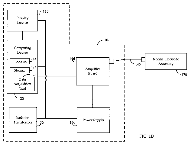
[0080] Figure 1B illustrates a simplified system control unit 108 for
controlling a needle
electrode assembly 170 according to an embodiment. System control unit 108 may
include one or
more elements, such as a computing device 120, a display device 130, an
amplifier board 140, an
isolation transformer 150, and a power supply 160 (e.g., a DC power supply).
System control unit
108 may be the same as that discussed with reference to Figure 1A, and needle
electrode assembly
170 may include one or more electrodes such as electrodes 102 discussed with
reference to
Figure 1A. Accordingly, in some embodiments, system control unit 108 may
control electrodes in
electrode assembly 170 to deliver electric fields to tissue for tissue
ablation. Further, as discussed
herein, system control unit 108 may optionally also utilize thermistors
provided within needle
-9-
CA 02857050 2014-05-26
WO 2013/090528 PCT/US2012/069430
electrode assembly 170 to monitor temperatures; e.g., temperatures of tissue
in regions proximate to
the electrodes.
[0081] Computing device 120 may include, e.g., a computer or a wide variety
of proprietary or
commercially available computers or systems having one or more processing
structures, a personal
computer, and the like, with such systems often comprising data processing
hardware and/or
software configured to implement any one (or combination of) the processing
operations described
herein. Any software will typically include machine readable code of
programming instructions
embodied in a non-transitory tangible media such as an electronic memory, a
digital or optical
recovering media, or the like, and one or more of these structures may also be
used to transmit data
and information between components of the system in any wide variety of
distributed or centralized
signal processing architectures. According to one embodiment, computing device
120 includes a
single core or multi-core processor 122 and a tangible non-transitory computer-
readable storage
device 124, where processor 122 may execute computer-readable code stored in
storage device 124.
[0082] Display device 130 may be any type of suitable device for displaying
information to an
operator of system control unit 108. For example, display device 130 may
incorporate cathode ray
tubes, liquid crystals, light emitting diodes, electrically charged ionized
gases (i.e., a plasma
display), and the like. In some embodiments, system control unit 108 may
further include one or
more input devices (not shown), such as a mouse, keyboard, keypad, trackball,
light pen, and the
like. Such input devices may be electrically coupled to computing device 120
to enable the operator
of system control unit 108 to provide inputs to computing device 120. In other
embodiments,
display device 130 may additionally or alternatively enable the operator of
system control unit 108
to provide inputs to computing device 120. For example, display device 130 may
comprise a touch-
screen display.
[0083] Display device 130 is in communication with computing device 120 to
enable data to be
transferred between the two devices. For example, display device 130 may be
electrically coupled
to computing device 120 via a connecting cable. For another example, display
device 130 and
computing device 120 may communicate data to one another wirelessly over any
suitable wireless
communication protocol, such as BluetoothTm, IEEE 802.11, etc.
[0084] Amplifier board 140 may be any suitable amplifier for driving one or
more electrodes in
a needle electrode assembly 170 and/or receiving and communicating temperature
measurements
from needle electrode assembly 170. In some embodiments, amplifier board 140
is operable to
individually control at least one of a voltage and current amplitude and phase
applied to each of the
-10-
CA 02857050 2014-05-26
WO 2013/090528 PCT/US2012/069430
electrodes of electrode assembly 170. Amplifier board 140 may be operable to
sample at least one
of a voltage, current, and temperature of each of the electrodes. Amplifier
board 140 may also be
operable to electrically disconnect one or more of the electrodes, connect one
or more of the
electrodes to ground, or connect one or more of the electrodes to a driving
signal. For example,
amplifier board 140 may include, for each electrode, a relay for controlling a
state of the electrode.
In one embodiment, amplifier board 140 performs signal conditioning on at
least one of voltage,
current, and temperature measurements sampled from electrode assembly 170.
[0085] Amplifier board 140 may be electrically coupled to needle electrode
assembly 170 via,
for example, a cable assembly 145. Cable assembly 145 may enable communication
between
amplifier board 140 and needle electrode assembly 170, and may enable
amplifier board 140 to
provide power to electrodes of needle electrode assembly 170. According to one
embodiment,
electrode assembly 170 includes thermistor circuitry for calculating
temperatures of the electrodes.
In such a case, amplifier board 140 may route signals from the thermistor
circuitry to computing
device 120 and supply power to the thermistor circuitry. According to other
embodiments, other
devices may be capable of calculating temperatures of the electrodes. For
example, computing
device 120 may perform such calculations based on measurements received from
electrodes in
electrode assembly 170.
[0086] Computing device 120 may also include a data acquisition card 126.
Data acquisition
card 126 may be electrically or wirelessly coupled to amplifier board 140 and
may receive various
measurement data read by amplifier board 140. For example, data acquisition
card 126 may receive
voltage, current, and temperature measurements of each of the electrodes. In
some embodiments,
data acquisition card 126 may receive such measurements after amplifier board
140 has performed
signal conditioning.
[0087] According to some embodiments, data acquisition card 126 may further
be configured to
control amplifier board 140. For example, data acquisition card 126 may
provide a digital bit
stream to amplifier board 140 instruct amplifier board 140 to drive one or
more of the electrodes
and acquire various measurements. In some embodiments, the digital bit stream
may be clocked
into memory of amplifier board 140 and, as a result, field programmable gate
arrays (FPGAs) of
amplifier board 140 may configure various subcomponents of amplifier board 140
to output and
measure the desired signals. This may be done many times per second, allowing
for smooth,
closed-loop control of the system.
-11-
CA 02857050 2014-05-26
WO 2013/090528 PCT/US2012/069430
[0088] Isolation transformer 150 may be any suitable transformer for
transferring alternating
current (AC) power from an AC power source to one or more other elements of
the system, such as
computing device 120, display device 130, and direct current (DC) power supply
160, while
isolating such elements from the earth ground.
[0089] DC power supply 160 may be any suitable power supply for converting
AC power to DC
power. In some embodiments, DC power supply 160 converts AC power received
from isolation
transformer 150 to DC power and provides the DC power to amplifier board 140.
In other
embodiments, amplifier board 140 includes an AC/DC converter and receives AC
power directly or
uses battery power, thus obviating the need for DC power supply 160.
[0090] Needle electrode assembly 170 may be electrically coupled to
amplifier board 140 as
previously discussed. Needle electrode assembly 170 includes a plurality of
needle or elongated
electrodes. The electrodes may each generate an electric field based on a
voltage and current
provided by amplifier board 140. In some embodiments, one or more electrodes
may include or be
replaced by a thermistor for measuring a temperature of the electrodes or
within a vicinity of the
electrodes. In some cases, one or more electrodes are used for measuring
temperature, but not for
generating an electric field. For example, some electrodes may be used to
monitor temperature and
provide a reference temperature (e.g., a body temperature).
[0091] According to one embodiment, the electrodes may be individually
advanced and
positioned within a target tissue (e.g., a prostate tissue). Once the
electrodes are positioned, a
voltage can be applied to one or more of the electrodes, thereby causing
electrical fields, magnetic
fields, and currents to be generated in portions of the target tissue. Such
fields may be used, for
example, for tissue ablation to destroy cancerous and/or hyperplastic cells.
[0092] System control unit 108 in certain embodiments is a system for
controlling a needle
electrode assembly including various components such as a computing device
120, a display device
130, an amplifier board 140, an isolation transformer 150, and a DC power
supply 160. However, it
will be appreciated by those of ordinary skill in the art that the system
control unit could operate
equally well by having fewer or a greater number of components than are
illustrated in Figure 1B.
Thus, the depiction of system control unit 108 in Figure 1B should be taken as
being illustrative in
nature, and not limiting to the scope of the disclosure.
[0093] Electrode assembly
[0094] A system will typically include a plurality or array of electrodes
that operatively couple
to one or more components of a system (e.g., power source, etc) and can be
positioned in the tissue
-12-
CA 02857050 2014-05-26
WO 2013/090528 PCT/US2012/069430
for delivery of current field as described herein. Some of all of the
electrodes may be used for
delivery of a current field. For example, a plurality of electrodes may be
positioned in the tissue,
but only some of those electrodes used for delivery of a current field.
Various different electrode
configurations and assemblies can be utilized and may be suitable for current
field delivery as
described herein.
[0095] Figure 2A is a profile view of an exemplary electrode assembly 200
according to an
embodiment. Electrode assembly 200 includes a plurality of elongated
electrodes 210, a plurality of
flexible conductive wires 220, and a housing 230.
[0096] In one embodiment, elongated electrodes 210 are substantially
cylindrical in shape. A
distal end of elongated electrodes 210, for example, an end for penetrating
tissue of a patient, is
narrowed to a tip. Such narrowing may advantageously reduce penetration
resistance when
inserting the electrode into an object such as tissue of a patient. A proximal
end of elongated
electrodes 210 may be mechanically and electrically coupled to an end of a
corresponding
conductive wire 220. Accordingly, current, voltage, and/or temperature
measurements may be
communicated to and from electrodes 210 via the conductive wires 220. In other
embodiments,
elongated electrodes 210 may have other shapes, such as being elongated with a
square, rectangular,
or oval cross-section. In some embodiments, elongated electrodes 210 have a
variety or a
combination of shapes. Electrodes 210 are further discussed with reference to
Figures 3A to 3B.
[0097] Each of the plurality of wires 220 includes a first end and a second
end, where the first
end is mechanically coupled to one of electrodes 210 and the second end is
mechanically coupled to
an interface of housing 230. Each wire 220 may comprise one or more cores that
may be made of
any suitable conductive material, such as copper, aluminum, metal alloys,
coated metals, etc. In
case each wire comprises only a single core, the single core may be insulated
with a non-conductive
sheath made of any suitable insulating material, such as plastic, silk, etc.
In case each wire
comprises a plurality of conductive cores, each core may be insulated, and the
plurality of insulated
cores may then be bundled with, e.g., a further sheath. In some embodiments,
the further sheath
may also be made of non-conductive material.
[0098] In one embodiment, one or more of wires 220 includes a shielding
element. The
shielding element is operable to prevent EMI leakage and noise on measured
signals. The shielding
element may be made of any suitable material and may include, for example, a
braided or foil-type
shielding.
-13-
CA 02857050 2014-05-26
WO 2013/090528 PCT/US2012/069430
[0099] Each core may be operable to communicate any suitable signal or
signals to and/or from
electrodes 210. For example, each core may communicate electrical voltage,
resistance, and/or
current, and/or differences in voltage, resistance, and/or current, etc. This
may include treatment
signals, which may be any suitable signal for excising tissue, and may include
temperature
measurement signals, which may be any suitable signal for measuring a
temperature in, on, or
around electrodes 210.
[00100] The first end of each wire 220 may include an enlarged portion 222.
The enlarged
portion may be of any suitable shape. In one embodiment, enlarged portion 222
has a cross-section
having a shape that is the same shape as at least a portion of electrode 210.
In another embodiment,
enlarged portion 222 has a cross-section having a shape this is the same shape
as wire 220. For
example, enlarged portion 222 may have a cross-section in the shape of a
circle, oval, rectangle, etc.
Enlarged portion 222 may be enlarged such that a diameter of enlarged portion
222 is larger than a
diameter of other portions of wire 222. The diameter of enlarged portion 222
may be stay the same
along a length of enlarged portion 222, or may vary along the length of
enlarged portion 222. In
one embodiment, the diameter of enlarged portion 222 at an end proximate to
electrode 210 is larger
than the diameter of enlarged portion 222 at an end proximate to other
portions of wire 210. In
another embodiment, enlarged portion 222 may include a surface proximate to
electrode 210 that is
planar and perpendicular to a direction in which electrode 210 extends. In
some embodiments,
enlarged portion 222 may be part of electrode 210 rather than wire 220.
[00101] Enlarged portion 222 may serve one or more functions. In one
embodiment, enlarged
portion 222 may provide a location that is easy to grasp by a clinician. In a
further embodiment,
enlarged portion may protect and insulate connections between conductive cores
of a wire 220 and
portions of an electrode 210. In another embodiment, enlarged portion 222 may
provide a depth
stop for electrodes 210. For example, where a electrode guide 110 includes a
plurality of apertures
to allow electrodes 210 to pass through, the enlarged portions 222 may be
sized so that they abut the
electrode guide 110 and prevent electrodes 210 from passing entirely through
the electrode guide
110. In one embodiment, enlarged portions 222 may have a diameter larger than
a diameter of
receiving apertures of electrode guide 110. In another embodiment, enlarged
portion 222 may have
a cross section having a shape that is different than a shape of a receiving
aperture of electrode
guide 110.
[00102] Housing 230 selectively receives the plurality of electrodes 210 and
includes an interface
for providing an electrical coupling to electrodes 210. Housing 230 may
further include apertures
-14-
CA 02857050 2014-05-26
WO 2013/090528 PCT/US2012/069430
for receiving the plurality of electrodes 210, and electronics for calculating
thermal measurements,
passing voltages and currents to electrodes 210, and the like. The interface
may include a first
interface portion mechanically coupled to wires 220, and a second interface
portion for receiving a
cable assembly from amplifier board 140 such as cable assembly 145.
[00103] Housing 230 may be any suitable shape. For example, as illustrated in
Figure 2A,
housing 230 may have substantially rectangular cross sections. For another
example, housing 230
may have substantially square, circular, or oval cross sections, or cross
sections of any other
suitable shape. Housing 230 may be made of any suitable material. For example,
housing 230 may
be made of organic solids such as polymers, composite materials such as
thermoplastic matrices,
metals, ceramics, etc.
[00104] Figure 2B is a top view of the electrode assembly of Figure 2A with
electrodes
disengaged from a housing. According to one embodiment, housing 230 includes a
top surface 232,
a bottom surface (not shown), and side surfaces 234(a) to 234(d). In this
embodiment, top surface
232 and side surfaces 234(a) to 234(d) are substantially planar and are
substantially perpendicular to
one another. However, in other embodiments, such surfaces may be curved or
angled, and provided
at angles other than 90 degrees. Further, wires 220 are mechanically coupled
to side surface 234(a).
However, in other embodiments, wires 220 may be mechanically coupled to other
surfaces, such as
the top surface, the bottom surface, and the like.
[00105] Figure 2C is a first side view of the electrode assembly of Figure 2A.
According to one
embodiment, housing 230 includes a first portion of an interface 236(a) for
mechanically coupling
to wires 220. Interface portion 236(a) includes conductive components such
that the mechanical
coupling provides an electrical coupling to wires 220 and electrodes 210.
According to this
embodiment, interface portion 236(a) is provided on side 234(a). However,
according to other
embodiments, interface portion 236(a) may be provided on any of the other
surfaces of housing 230.
[00106] Figure 2D is a second side view of the electrode assembly of Figure
2A. According to
one embodiment, housing 230 includes a second portion of an interface 236(b)
for mechanically
coupling to a cable such as cable assembly 145. Interface portion 236(b)
includes conductive
components such that the mechanical coupling provides an electrical coupling
to conductive cores
in cable assembly 145. According to this embodiment, interface portion 236(b)
is provided on side
234(c). However, according to other embodiments, interface portion 236(b) may
be provided on
any of the other surfaces of housing 230.
-15-
CA 02857050 2014-05-26
WO 2013/090528 PCT/US2012/069430
[00107] As previously mentioned, housing 230 may include electronics for
calculating thermal
measurements, passing voltages and currents to electrodes 210, and the like.
For example, housing
230 may surround or embody a printed circuit board (PCB) having circuitry
and/or software for
calculating thermal measurements from electrodes 210. The PCB may be partially
or fully
disposed, mechanically and electrically, between interface portion 236(a) and
interface portion
236(b). Housing 230 may also include electronics for storing data. Stored data
may include
identification data such as a serial number, mode number, expiration data,
authentication code, etc.
In some embodiments, such stored data may be read by various computing
devices, such as
computing device 120.
[00108] Figure 2E is a third side view of the electrode assembly of Figure 2A.
According to one
embodiment, housing 230 includes a plurality of apertures 238 for receiving
the plurality of
electrodes 210. Apertures 238 may each have a shape corresponding to an
electrode 210. For
example, apertures 238 may protrude into a depth of housing 230 and have a
substantially circle
cross-section. However, apertures 238 may have other shapes as well, such as
rectangular, square,
or oval cross-sections. In some embodiments, apertures 238 may be spaced apart
from one another
so as to electrically insulate electrodes 210 from one another when housing
230 receives electrodes
210. According to one embodiment, apertures 238 are provided on side 234(b).
However,
according to other embodiments, apertures 238 may be provided on any of the
other surfaces of
housing 230.
[00109] Figure 2F is a top view of the electrode assembly of Figure 2A with
electrodes engaged
with a housing. By engaging the electrodes into the housing, the electrodes
may advantageously be
protected during transportation, and the electrode assembly may advantageously
be handled after
sterilization of the electrodes.
[00110] According to one embodiment, housing 230 may receive electrodes 210
via apertures
238. Housing 230 may use any suitable mechanism for maintaining electrodes 210
within apertures
238 so as to advantageously reduce the likelihood of electrodes 210
unexpectedly disengaging from
apertures 238. For example, electrodes 210 may have a friction fit with
apertures 238. Upon
engaging electrodes 210 with apertures 238, enlarged portions 222 of wires 220
may extend from a
side surface of housing. In one embodiment, apertures 238 and enlarged
portions 222 may be sized
to create a friction fit between enlarged portions 222 and apertures 238.
[00111] Electrode assembly 200 in certain embodiments is an assembly of
electrodes for
generating electric fields so as to create current patterns in a delivery
medium, and may include
-16-
CA 02857050 2014-05-26
WO 2013/090528 PCT/US2012/069430
various components such as elongated electrodes 210, flexible conductive wires
220, and a housing
230. However, it will be appreciated by those of ordinary skill in the art
that the electrode assembly
could operate equally well by having fewer or a greater number of components
than are illustrated
in Figures 2A to 2F. Thus, the depiction of electrode assembly 200 in Figures
2A to 2F should be
taken as being illustrative in nature, and not limiting to the scope of the
disclosure.
[00112] For example, in some embodiments, electrode assembly 200 may consist
only of
elongated electrodes 210. In such cases, electrodes 210 may be controlled by
electrode guide 110,
and/or information may be communicated to and from the electrodes via
electrode guide 110. For
example, receiving apertures of electrode guide 110 may each include
electrical contacts for
electrically contacting a received electrode. The electrical contacts may then
operate to
communicate current to and/or from received electrodes. The electrical
contacts may be powered
and/or in wired or wireless communication with other parts of system 100, such
as system control
unit 108, so as to facilitate power transfer and/or information communication
between electrodes
210 and system control unit 108. In some embodiments, electrodes 210 may
include circuitry such
as a wireless communication interface and/or a power supply, so that
electrodes 210 may be in
wireless communication with parts of system 100 such as system control unit
108 and/or may
communicate current to and/or from a target area regardless of whether
electrode guide 110
includes elements for controlling and/or powering electrodes 210.
[00113] Figure 3A is a profile view of an electrode 300 according to an
embodiment. Electrode
300 includes an exposed portion 310 and an insulated portion 320. Exposed
portion 310 includes a
conductive surface and a sharpened point, and is operable to deliver a
treatment signal to tissue.
The exposed portion 310 may be made of any suitable conductive material, such
as copper,
aluminum, metal alloys, coated metals, etc. In some embodiments, the exposed
portion 310 of an
electrode may be operable to conduct current to another electrode or
conductive entity, so as to
generate heat by way of the current path. In other embodiments, the exposed
portion 310 of an
electrode may be operable to generate heat itself, so that the heat generated
is localized to the
exposed portion 310. For example, the exposed portion 310 may be made of any
suitable resistive
material, such as carbon, carbon composites, metal, coated metal, metal-oxide,
etc. Insulated
portion 320 includes a non-conductive surface. The insulated portion 320 may
be made of any
suitable non-conductive material and, in some embodiments, may include a
sheath wrapped around
other parts of electrode 300, where the sheath is made of any suitable non-
conducive material. For
-17-
CA 02857050 2014-05-26
WO 2013/090528 PCT/US2012/069430
example, a heat shrink sleeve may be applied to the entire electrode 300
except for the exposed
portion 310. The heat shrink sleeve may be made of, e.g., a polymer.
[00114] Exposed portion 320 may have any suitable length. For example, exposed
portion 320
may have a length equal to lcm, 2cm, 3cm, or in a range between lcm and 3cm,
or less than lcm,
or greater than 3cm. The distance from the sharpened tip of electrode 300 may
be indicated on an
exterior surface of electrode 300. For example, distances of lcm, 2cm, 3cm,
etc. may be marked on
the surface of electrode 300. The indications may be made using any suitable
method, such as
chemical marking, laser marking, a printing process, etc.
[00115] Electrode 300 may have any suitable shape, size, and/or diameter, and
electrode design
or configuration may be selected based on the particular use of the system or
aspects of a particular
treatment to be performed. For example, electrode 300 may have a diameter of
approximately 18
gauge, or a diameter in the range of 16 gauge to 20 gauge, or lower than 16
gauge or higher than 20
gauge. Electrode 300 may have any suitable length. For example, electrode 300
may have a length
of approximately 20 cm, or a length in the range of 15 cm to 25cm, or less
than 15 cm or greater
than 25 cm. According to one embodiment, electrode 300 is in the shape of a
brachytherapy-style
needle. According to other embodiments, electrode 300 is in a shape other than
a needle, such as a
catheter.
[00116] Figure 3B is a cross-sectional view of the electrode of Figure 3A.
From the cross-
sectional view, various components of an electrode according to one embodiment
as visible.
According to this embodiment, electrode 300 includes an exposed portion 310,
insulated portion
320, a temperature sensor 330, temperature sensor lead 340, and electrode
leads 350. From this
perspective, it is apparent than in this embodiment, insulated portion 320 may
form a shell or outer
coating for other elements of electrode 300 to be arranged in. Exposed portion
320 includes a
sharpened portion extending from insulated portion 320, and also includes a
supporting portion that
extends into insulated portion 320.
[00117] Temperature sensor 330 is operable to measure a temperature of or
proximate to
electrode 300. Temperature sensor 330 may be any suitable element for
measuring temperature.
For example, temperature sensor 330 may be a thermistor, thermocouple,
resistive thermal device
(RTD), etc. Temperature sensor 330 may be made of any suitable material. For
example, sensor
330 may be made of platinum, platinum-covered ceramic, wire, glass-covered
wire, one or more
alloys, metals, etc. In this embodiment, temperature sensor 330 is arranged
beside exposed portion
-18-
CA 02857050 2014-05-26
WO 2013/090528 PCT/US2012/069430
310. In one embodiment, electrode 300 includes a plurality of temperature
sensors 330, either of
the same or different type.
[00118] Electrode 300 includes one or more sensor leads 340 for communicating
signals from
sensor 330. Sensor lead 340 may be mechanically and electrically coupled to
one or more cores of
a wire 220. Sensor lead 340 may communicate any suitable signal from sensor
330. For example,
sensor lead 340 may communicate electrical voltage, resistance, and/or
current, and/or differences
in voltage, resistance, and/or current, etc. Electrode 300 also includes one
or more electrode leads
350 for communicating a treatment signal to exposed portion 310. Electrode
lead 350 may be
mechanically and electrically coupled to one or more cores of a wire 220 and,
in some
embodiments, to cores in the same wire 220 in which sensor lead 340 is coupled
to. The treatment
signal may be any suitable signal for excising tissue; for example, it may be
a voltage, a current, etc.
[00119] Temperature sensor 330 and its lead(s) may be included in one, some,
all, or none of
plurality of elongated electrodes 210. Similarly, exposed portion 310 may be
included in one,
some, all, or none of elongated electrodes 210. In some embodiments, exposed
portion 310 may
function as a temperature sensor 330. In such a case, the electrode 210 may or
may not include
elements for delivering a treatment signal, and in such a case exposed portion
310 may or may not
be sharpened to a point.
[00120] In one embodiment, electrode 300 includes multiple exposed areas. For
example,
insulated portion 320 may include one or more apertures for exposing portions
of electrode 300. In
one case, a portion of temperature sensor 330 may be exposed. In another case,
a portion of one or
more other element (e.g., a conductive material such as a metal, alloy, etc.)
for delivering a
treatment signal may be exposed. In such a case, electrode 300 may include
multiple exposed
portions for delivering multiple treatment signals either dependent or
independent of one another.
In yet another case, multiple exposed portions 310 may extend from one or more
insulated portions
320, where each exposed portion 310 may or may not be sharpened to a point. In
such a case,
electrode 300 may also deliver multiple treatment signals, and may include
none, one, or more
temperature sensors 330.
[00121] In another embodiment, electrode 300 may be flexible or include one or
more flexible
elements. For example, electrode 300 may be a catheter, where leads are
coupled to the catheter
needle so as to communicate a treatment signal to the needle. The catheter may
or may not include
one or more temperature sensors.
-19-
CA 02857050 2014-05-26
WO 2013/090528 PCT/US2012/069430
[00122] In some embodiments, electrode 300 may be solid or include solid
elements, such as a
solid exposed portion 310 and temperature sensor 320. In other embodiments,
electrode 300 may
include hollow portions. For example, exposed portion 310 may include a hollow
chamber. Other
elements of electrode 300 may also include a hollow chamber. For example, a
hollow chamber may
extend the length of electrode 300. The hollow chamber may be operable to
communicate fluid or
the like. For example, blood, water, or other fluids may pass in either
direction through the hollow
chamber.
[00123] Electrode 300 in certain embodiments may include various components
such as an
exposed portion 310, an insulated portion 320, a temperature sensor 330, a
temperature sensor lead
340, and electrode leads 350. However, it will be appreciated by those of
ordinary skill in the art
that the electrode could operate equally well by having fewer or a greater
number of components
than are illustrated in Figures 3A and 3B. Thus, the depiction of electrode
300 in Figures 3A and
3B should be taken as being illustrative in nature, and not limiting to the
scope of the disclosure.
[00124] For example, in some embodiments electrode 300 may include a light
source (not
shown) such as a light emitting diode (LED). The light source may be operable
to selectively
output light such that a medical practitioner can visibly see the light. This
may be useful for a
practitioner to identify a particular, selected electrode. The light source
may be provided in any
suitable location, such as on an exterior surface of insulated portion 320 or
beneath a transparent
surface of insulated portion 320, or at an end of electrode 300 such as the
end connected to flexible
conductive wire 220. In one embodiment, computing device 120 provides an
option via display
device 130 for a user to locate or otherwise identify one or more electrodes.
In response to
receiving a user input selecting a particular electrode to locate, computing
device 120
communicates an instruction to needle electrode assembly 170 and, in
particular, to the electrode
corresponding to the selected electrode. The instruction instructs the
selected electrode to generate
light such as via a light source provided in the electrode. Accordingly, in
such embodiments,
electrode 300 may include circuitry or other components operable to receive
and interpret the
received instruction and cause the light source to output light in response to
receiving such an
instruction.
[00125] Electrode guide
[00126] A system will typically include an electrode guide or positioning
device or apparatus.
An electrode guide will typically be configured to engage electrodes of the
system for assistance or
facilitation of electrode positioning in the tissue of the patient. A guide
may optionally include
-20-
CA 02857050 2014-05-26
WO 2013/090528 PCT/US2012/069430
electrical connects that electrically couple with or in some manner
facilitate, monitor, or affect
energy delivery, monitoring, or control of current delivery. Various different
designs or
configurations of an electrode guide may be included in a system of the
present invention.
[00127] Figure 4A is a profile view of an exemplary electrode guide 400
according to an
embodiment. Electrode guide 400 includes a plurality of electrode templates
and an adjustable
template securing apparatus 450. In one embodiment, electrode guide 400 may
correspond to the
electrode guide 110 discussed with reference to system 100.
[00128] Electrode guide 400 may include any suitable number of templates. In
one embodiment,
electrode guide 400 includes a first electrode template 420 and a second
electrode template 430.
The electrode templates may be any suitable template operable to receive
electrodes and, in some
embodiments, allow the electrodes to pass therethrough. The electrode
templates may be any
suitable shape. For example, they may have a cross section that is square,
rectangular, circular,
oval, or any other suitable shape.
[00129] First electrode template 420 may include one or more apertures 440
formed partially or
entirely through a depth of the template. Apertures 440 may have any suitable
shape, such as
circular, square, rectangular, oval, etc., and may be of any suitable size.
For example, apertures 440
may be sized to receive an electrode such as elongated electrode 210 discussed
with reference to
Figure 2A, and, in some embodiments, sized to form a friction fit with the
electrode. In one
embodiment, apertures 440 may be sized not to receive a portion of the
electrode. For example,
apertures 440 may be sized smaller than at least one dimension of enlarged
portion 222 discussed
with reference to Figure 2A. In some embodiments, apertures 440 all have the
same size, all have
different sizes, or some have the same size while others have at least one
different size. Apertures
440 may be spaced apart from one another by any suitable distance. For
example, apertures 440
may be spaced apart from one another a distance of lmm, 2mm, 3mm, 4mm, or 5mm,
or a distance
in the range of lmm to 5mm, or a distance of less than lmm or greater than
5mm. Apertures 440
may also be arranged in any suitable pattern. For example, apertures 440 may
be arranged in one or
more squares, circles, ovals, rectangles, or the like, or a combination
thereof. In one embodiment,
apertures 440 are arranged in equally spaced rows and columns. Each row and/or
column may have
the same number or a different number of apertures 440. Second electrode
template 430 may
include one or more apertures similar to those discussed with reference to
first electrode template
420.
-21-
CA 02857050 2014-05-26
WO 2013/090528 PCT/US2012/069430
[00130] In one embodiment, at least one of first electrode template 420 and
second electrode
template 430 includes an electronic circuit (not shown). For example, an
electrode template may
include a printed circuit board. The electronic circuit may include hardware
and/or software for
performing a variety of functions. For example, the electronic circuit may
include conductive
components for electrically coupling with an electrode disposed in an aperture
of the electrode
template. In such a fashion, a presence or absence of an electrode may be
detected by the electronic
circuit. The electronic circuit may then be communicatively coupled to other
elements for
communicating indications of the presence or absence of electrodes in one or
more of the electrode
templates. For example, the electronic circuit may be communicatively coupled
to computing
device 120.
[00131] In some embodiments, first electrode template 420 includes at least
one securing element
(not shown) extending from a surface of the template. For example, the at
least one securing
element may be a pin (not shown) extending from a bottom surface of the
template. The securing
element may be operable to mechanically couple first electrode template 420 to
adjustable template
securing apparatus 450. One embodiment of the at least one securing element is
further discussed
with reference to Figure 4B. Second electrode template 430 may include one at
least one securing
element (not shown) similar to that discussed with reference to first
electrode template 420. In one
embodiment, first electrode template 420 and second electrode template 430
each include two or
more securing elements.
[00132] Adjustable template securing apparatus 450 is operable to secure the
plurality of
electrode templates with respect to one another and adjust a distance between
the plurality of
electrode templates. In one embodiment, adjustable template securing apparatus
450 is operable to
secure first electrode template 420 with respect to second electrode template
430 and adjust a
distance between first electrode template 420 and second electrode template
430.
[00133] According to an embodiment, adjustable template securing apparatus 450
includes a first
template mount 460, a second template mount 470, and a distance adjustment
element 480. First
template mount 460 may be operable to support first electrode template 420.
For example, first
template mount 460 may be mechanically couplable to distance adjustment
element 480 and secure
a position of first electrode template 420 relative to first template mount
460. First template mount
460 may be mechanically couplable to first electrode template 420 using any
suitable mechanical
coupling. For example, first electrode template 420 may be bonded to first
template mount 460.
For another example, first electrode template 420 may engage a cutout or
aperture of first template
-22-
CA 02857050 2014-05-26
WO 2013/090528 PCT/US2012/069430
mount 460. For yet another example, first template mount 460 may include one
or more cutouts
462 each for receiving one or more securing elements (not shown) of first
electrode template 420.
In one embodiment, first template mount 460 includes two cutouts 462 arranged
at opposite sides of
first electrode template 420. In some embodiments, adjustable template
securing apparatus 450
may also include at least one tightening element 492 for adjusting the
strength of a mechanical
coupling between first electrode template 420 and first template mount 460.
For example,
tightening element 492 may be a screw or other rotatable element operable to
increase and/or
decrease a size of cutout 462, where decreasing the size of cutout 462 results
in an increased
pressure on the securing element of first electrode template 420 by first
template mount 460. In one
embodiment, adjustable template securing apparatus 450 includes one tightening
element 492 for
each cutout 462.
[00134] Second template mount 470 may include some or all of the features
discussed above for
first template mount 460. For example, second template mount 470 may include a
cutout 472
similar to cutout 462. Further, in some embodiments, adjustable template
securing apparatus 450
may include one or more tightening elements 494 similar to the at least one
tightening element 492,
where the tightening elements 494 are operable to adjust the strength of a
mechanical coupling
between second electrode template 430 and second template mount 470.
[00135] In some embodiments, second template mount 470 is removably secured to
distance
adjustment element 480. Second template mount 470 may be removably secured to
distance
adjustment element 480 using any suitable mechanical coupling mechanism. For
example, second
template mount 470 may include a clasp, strap, or the like (not shown) for
mechanically coupling to
distance adjustment element 480. For another example, second template mount
470 may include
one or more apertures 474 extending through a depth of second template mount
470. Aperture 474
may be any suitable shape and size to receive distance adjustment element 480
and allow distance
adjustment element 480 to pass therethrough. In one embodiment, second
template mount 470
includes two apertures 474 arranged on opposite sides of second electrode
template 430. In some
embodiments, template securing apparatus 450 may also include one or more
tightening elements
496, similar to tightening element 492, for adjusting the strength of a
mechanical coupling between
distance adjustment element 480 and second template mount 470. For example,
template securing
apparatus 450 may include one tightening element 496 for each aperture 474.
[00136] Distance adjustment element 480 may be any suitable device operable to
adjustably
secure first electrode template 420 to second electrode template 430. In one
embodiment, distance
-23-
CA 02857050 2014-05-26
WO 2013/090528 PCT/US2012/069430
adjustment element 480 includes one or more cylindrically-shaped rods,
although it may have any
suitable cross-section shape, such as square, rectangular, oval, and the like.
Distance adjustment
element 480 may be removably secured to one or more of the plurality of
electrode templates. In
some embodiments, distance adjustment element 480 may be bonded to one or more
of the plurality
of electrode templates. For example, distance adjustment element 480 may be
mechanically bonded
to first template mount 460. In one embodiment, distance adjustment element
480 includes a pair of
rods. Distance adjustment element 480 may include distance markers 482 that
may be evenly
spaced visual indicators indicating a distance along a length of distance
adjustment element 480.
For example, distance markers 482 may illustrate numerical values increasing
in value from first
template mount 460 so that a distance from first template mount 460 to second
template mount 470
may be easily identified. Distance adjustment element 480 may be made of any
suitable solid
material, including metal, metal alloys, ceramic, polymers, etc.
[00137] Figure 4B is a front view of the electrode guide of Figure 4A. From
the front view, the
second electrode template 430 and second template mount 470 are visible, as
are other elements
such as apertures 474, adjustment elements 480, and tightening elements 494
and 496. Further, the
previously mentioned securing elements 432 are shown.
[00138] Securing element 432 may be any suitable element extending from a
surface of second
electrode template 430 to removably secure second electrode template 430 to
second template
mount 470. For example, securing element 432 may be a pin-shaped extension
extending from a
bottom surface 434 of second electrode template 430, where a distal end of
securing element 432 is
sized larger than a proximal end of securing element 432 mechanically coupled
to or formed with
bottom surface 434. Securing element 432 may be sized to engage cutout 472.
Further, tightening
element 494 may be operable to increase or decrease a size of cutout 472 so as
to increase or
decrease a mechanical coupling between second electrode template 430 and
second template mount
470.
[00139] Figure 4C is a side view of the electrode guide of Figure 4A. From the
side view, first
electrode template 420, first template mount 460, second template mount 470,
and distance
adjustment element 480, as well as various other components of electrode guide
400, are visible.
[00140] In one embodiment, first electrode template 420 and second electrode
template 430 are
each arranged such that corresponding apertures in the templates are provided
at identical distances
from distance adjustment element 480 along a Y-axis. For example, first
electrode template 420
and second electrode template 430 may be arranged in parallel along a Z-axis
and be oriented to
-24-
CA 02857050 2014-05-26
WO 2013/090528 PCT/US2012/069430
extend along the Y-axis. Apertures 440 provided in first electrode template
420 may be aligned
along the Y-axis with apertures 440 provided in second electrode template 430.
For example, an
aperture provided at location E-5 in first electrode template 420 may be
provided at a same height
(H) relative to distance adjustment element 480 as an aperture provided at
location E-5 in second
electrode template 430.
[00141] Figure 4D is a top view of the electrode guide of Figure 4A. From the
top view, first
electrode template 420, first template mount 460, second template mount 470,
and distance
adjustment element 480, as well as various other components of electrode guide
400, are visible.
[00142] In one embodiment, first electrode template 420 and second electrode
template 430 are
each arranged such that corresponding apertures in the templates are provided
at identical distances
from a distance adjustment element 480 along an X-axis. For example, first
electrode template 420
and second electrode template 430 may be arranged in parallel along a Z-axis
and be oriented to
extend along the X-axis. Apertures 440 provided in first electrode template
420 may be aligned
along the X-axis with apertures 440 provided in second electrode template 430.
For example, an
aperture provided at location E-5 in first electrode template 420 may be
provided at a same distance
(D) from a distance adjustment element 480 as an aperture provided at location
E-5 in second
electrode template 430.
[00143] By providing apertures 440 in first electrode template 420 in
horizontal and vertical
alignment with apertures 440 in second electrode template 430, the stability
of an electrode passing
through the templates may advantageously be increased as well as an accuracy
of disposing the
electrode into a target area.
[00144] Electrode guide 400 in certain embodiments is an apparatus for
controlling the
placement and positioning of electrodes and may include various components
such as a plurality of
electrode templates and an adjustable template securing apparatus. However, it
will be appreciated
by those of ordinary skill in the art that such an apparatus could operate
equally well with fewer or a
greater number of components than are illustrated in Figures 4A to 4D. Thus,
the depiction of
electrode guide 400 should be taken as being illustrative in nature, and not
limiting to the scope of
the disclosure.
[00145] For example, electrode guide 400 need not support electrodes operable
to conduct
current into a target area. Rather, in some embodiments, electrode guide 400
may be operable to
support and/or guide radiation sources for applying radiation to a target
area, such as in
brachytherapy. In other embodiments, electrode guide 400 may be operable to
support and/or guide
-25-
CA 02857050 2014-05-26
WO 2013/090528 PCT/US2012/069430
needles or other devices for removing samples from the target area, such as in
biopsies.
Accordingly, electrode guide 400 may be operable to support a wide variety of
instruments, medical
or otherwise, for a variety of purposes.
[00146] Template
[00147] Electrode guides typically include one or more templates for operable
to receive
electrodes and, in some embodiments, allow the electrodes to pass
therethrough. The templates
may include one or more characteristics for resiliently positioning one or
more electrodes received
therein. By such resilient positioning, once an electrode has been placed in
the template, accidental
movement of the electrode may advantageously be reduced. As previously
discussed, in one
embodiment, the template(s) may include apertures suitably sized and shape to
form a friction fit
with an electrode. In other embodiments, the template(s) may include a
friction plate operable to
selectively change (e.g., increase or decrease) a friction force applied to
one or more electrodes
received by the template(s). By being operable to selectively change a
friction force applied to
electrodes, a position of electrodes may be substantially fixed once their
appropriate position
determined and, in some cases, re-positioning of the electrodes may easily be
performed.
[00148] Figure 5A is a profile view of a template 500 according to an
embodiment. Template
500 may be a stand-alone template or, in some embodiments, may be the same as
and incorporate
one or more features of first electrode template 420 and/or second electrode
template 430.
[00149] Template 500 includes one or more apertures 510 formed partially or
entirely through a
depth of the template. Apertures 510 may be similar to apertures 440. Template
500 also includes
a friction adjustment mechanism 520 operable to change a friction force
applied to one or more
electrodes provided in apertures 510. Friction adjustment mechanism 520 may
assume any suitable
mechanical structure for causing displacement of elements of template 500. In
one embodiment and
as shown in Figure 5A, friction adjustment mechanism 520 is a rotatable lever,
where rotation in
one direction causes an friction force applied to electrodes disposed in
apertures 510 to increase,
and rotation in an opposite direction causes the friction force applied to the
electrodes to decrease.
Other suitable mechanical structures include, but are not limited to, buttons,
clamps, transverse
actuators (i.e., non-rotational), etc.
[00150] Figure 5B is a front view of the template of Figure 5A. The front view
is a view of
template 500 in the X-Y plane, taken at a depth Z into template 500. From the
front view, it is
apparent that template 500 may include a housing 530 having a cavity 540
formed therein.
Template 500 also includes a friction plate 550 disposed within cavity 540.
Friction plate 550 is
-26-
CA 02857050 2014-05-26
WO 2013/090528 PCT/US2012/069430
formed smaller than cavity 540 such that a position of friction plate 550
within cavity 540 may be
changed in response to actuation of friction adjustment mechanism 520.
Friction plate 550 includes
one or more apertures 552 corresponding to apertures provided in frame 530 so
as to form apertures
510 that pass through template 500. Apertures 552 may have any size and shape
such that, upon
actuation of friction adjustment mechanism 520, friction plate 550 operates to
apply a friction force
to electrodes disposed therethrough. For example, apertures 552 may be the
same size, larger, or
smaller than corresponding apertures in housing 530, and may all have the same
or different sizes
and/or shapes. In one embodiment, apertures 552 and the apertures in housing
530 are circular, and
a diameter of apertures 552 is greater than or equal to the diameter of the
apertures in housing 530.
Friction plate 550 may be made of any suitable material for applying a
friction force to electrodes
disposed therethrough. For example, friction plate 550 may be made of a
polymer such as plastic,
one or more metals, ceramic, etc.
[00151] Template 500 may also include one or more elements operable to move
friction plate
550 in conjunction with friction adjustment mechanism 520. For example,
template 500 may
include one or more return springs 560 operable to apply a return force to
friction plate 550. In one
embodiment, return springs 560 may apply a force on friction plate 550 in a
direction opposite a
force applied to friction plate 550 by friction adjustment mechanism 520. For
example, friction
adjustment mechanism 520 may include a cam 522 that, when rotated in a first
direction, applies a
linear force to friction plate 550 along the Y-axis. In response to applying
the force to friction plate
550, friction plate 550 is caused to be displaced within cavity 540 along the
Y-axis, such that a size
of apertures 510 is effectively reduced. Return springs 560 apply a return
force along the Y-axis in
a direction opposite the direction of the force applied by rotation of cam 522
in the first direction.
As a result, the force applied by return springs 560 operates to assist in
returning friction plate 550
to its original position when cam 522 is rotated in a second direction
opposite the first direction.
[00152] Figure 5C is a cross sectional view of the template of Figure 5A. From
the cross
sectional view, it is apparent that template housing 530 includes apertures
532 disposed on a front
surface of housing 530 and apertures 534 disposed on a rear surface of housing
530. Apertures 532
and apertures 534 may have any suitable size and shape for receiving
electrodes. In one
embodiment, apertures 534 are elongated in a direction along the Z-axis,
thereby increasing support
for electrodes such as electrode 502 disposed therethrough.
[00153] According to some embodiments, friction plate 550 may be a multi-
layered structure. A
first layer 552 may be a support structure that is relatively hard. For
example, first layer 552 may
-27-
CA 02857050 2014-05-26
WO 2013/090528 PCT/US2012/069430
be made of metal, ceramic, or one or more other relatively hard materials. A
second layer 554 may
be supported by first layer 552 and, in some embodiments, may be formed on a
surface of first layer
552. Second layer 554 may be made of a relatively soft material (compared to
first layer 552). For
example, second layer 554 may be made of a polymer such as plastic. In these
embodiments, first
layer 552 may mechanically interact with cam and return springs 560 and, by
its relatively hard
physical nature, be resilient to long-term use and the wear resulting
therefrom. Second layer 554,
on the other hand, may mechanically interact with one or more electrodes 502
passing through
friction plate 550 and, by its relatively soft physical nature, be operable to
apply a friction force to
electrode 502 without damaging electrode 502. To facilitate such an operation,
first layer 552 and
second layer 554 may each have apertures corresponding to apertures of housing
530, where
apertures of second layer 554 may be smaller than apertures of first layer
552. As a result, second
layer 554 may include an electrode interference portion 556 operable to engage
or otherwise
mechanically interfere with electrode 502.
[00154] Template 500 in certain embodiments is a device operable to
selectively apply a friction
force to received electrodes and may include various components such as a
movable friction plate,
friction adjustment mechanism, and return springs. However, it will be
appreciated by those of
ordinary skill in the art that such a system could operate equally well with
fewer or a greater
number of components than are illustrated in Figures 5A to 5C. Thus, the
depiction of template 500
should be taken as being illustrative in nature, and not limiting to the scope
of the disclosure.
[00155] Figure 6 is a flowchart depicting example operations of a method 600
for controlling a
position of one or more elongated electrodes. The electrodes may be any
suitable elongated
element, including any of the electrodes previously discussed such as
electrode 102 of Figure 1A.
[00156] In operation 610, a first electrode template is provided. The first
electrode template may
be any suitable device for receiving and supporting elongated electrodes. For
example, the first
electrode template may correspond to first electrode template 420 discussed
with reference to
Figure 4A. Accordingly, the first electrode template may include a plurality
of apertures arranged
to receive one or more elongated electrodes.
[00157] In operation 620, a second electrode template is provided. The second
electrode
template may be any suitable device for receiving and supporting elongated
electrodes. For
example, the second electrode template may correspond to second electrode
template 430 discussed
with reference to Figure 4A. Accordingly, the second electrode template may
include a plurality of
apertures arranged to receive one or more elongated electrodes.
-28-
CA 02857050 2014-05-26
WO 2013/090528 PCT/US2012/069430
[00158] In operation 630, the first electrode template is arranged a first
distance from the second
electrode template. For example, second electrode template 430 may be arranged
to contact first
electrode template 420 such that the first distance is 0 mm. For another
example, second electrode
template 430 may be arranged a distance of lOmm, 20mm, or 30mm from first
electrode template
420, or in a range from lOmm to 30mm, or less than lOmm or greater than 30mm.
[00159] The first electrode template may be arranged a first distance from the
second electrode
template using any suitable movement and securing mechanisms. For example,
with reference to
Figure 4A, a position of first electrode template 420 may be secured relative
to a position of
distance adjustment element 480 using first template mount 460. For example,
first electrode
template 420 may be removably secured to first template mount 460 by engaging
at least one
tightening element 492. A position of second electrode template 420 may
similarly be secured
relative to a position of distance adjustment element 480 using second
template mount 470. For
example, second electrode template 430 may be removably secured to second
template mount 470
by engaging at least one tightening element 494. Second electrode template 430
may be positioned
proximate to first electrode template 420 by passing distance adjustment
elements 480 through
apertures 474 of second template mount 470. Second electrode template 430 may
then be
positioned along distance adjustment element 480 a first distance from first
template mount 460.
Once second template mount 470 has been arranged the first distance from first
template mount
460, a position of second template mount 470 relative to first template mount
460 may be secured
by engaging tightening elements 496. In some embodiments, the positioning of
the second
electrode template may be mechanically and electronically controlled by any
suitable control
apparatus such as computing device 120 discussed with reference to Figure 1B.
[00160] In operation 640, the first electrode template is positioned proximate
a treatment object.
The treatment object may be any suitable object for which penetration of one
or more electrodes is
desired. For example, the treatment object may be a patient for which tissue
ablation of a prostate
(P) such as that discussed with reference to Figure lA is desired. By
proximate positioning, the first
electrode template is arranged at a fixed distance from the treatment object.
For example, first
electrode template 420 may be arranged to contact a surface of the treatment
object. For another
example, first electrode template 420 may be arranged a distance of lOmm,
20mm, or 30mm from a
surface of the treatment object, or in a range from lOmm to 30mm, or less than
lOmm or greater
than 30mm. In some embodiments, the positioning of the first electrode
template may be
-29-
CA 02857050 2014-05-26
WO 2013/090528 PCT/US2012/069430
mechanically and electronically controlled by any suitable control apparatus
such as computing
device 120 discussed with reference to Figure 1B.
[00161] In operation 650, an electrode is disposed through the first and
second templates. For
example, an elongated electrode may be disposed through an aperture of second
electrode template
430 (e.g., an aperture located at template position E-5) and through a
corresponding aperture of first
electrode template 420 (e.g., an aperture located at template position E-5).
The electrode may be
disposed to first enter and pass through the second template and then enter
and pass through the
second template. Upon passing through the second template, the electrode may
penetrate a surface
of the treatment object.
[00162] In one embodiment, the electrode may penetrate the treatment object to
a maximum
desired depth. For example, with reference to Figure 1A, a maximum desired
depth may
correspond to a rear wall of the prostate (P) that is located opposite an
electrode-penetrating surface
of the patient. In some embodiments, the treatment object may be monitored to
determine the
maximum desired depth. For example, imaging device/system 112 may graphically
monitor a
location of the electrode within the treatment object. The monitored images of
the electrode and
treatment object may be communicated for display by, for example, display
device 130. In one
embodiment, computing device 120 may determine the maximum desired depth by
setting the depth
based on a minimum distance between a penetration end of the electrode and the
rear wall of the
prostate (P). Further, in some embodiments, computing device 120 may be
operable to control the
penetration of electrode into the treatment object.
[00163] In operation 660, the second electrode template is repositioned to be
a second distance
from the first electrode template, where the second distance is greater than
the first distance. For
example, tightening elements 496 may be relaxed so as to enable second
template mount 470 to
move along distance adjustment element 480. Second template mount 470 may then
be moved in a
direction away from first template mount 460, so as to increase a distance
between first electrode
template 420 and second electrode template 430. This may be performed while
maintaining a fixed
distance between first electrode template 420 and the treatment object. In one
embodiment, the
elongated electrode includes an enlarged portion such as enlarged portion 222
discussed with
reference to Figure 2A, where the enlarged portion is sized to mismatch the
aperture of second
electrode template 430 which the electrode is disposed in. Second template
mount 470 may then be
moved away from first template mount 460 until the aperture which the
electrode is disposed in
contacts the enlarged portion of the electrode. In some embodiments, second
template mount 470
-30-
CA 02857050 2014-05-26
WO 2013/090528 PCT/US2012/069430
may then be re-secured to distance adjustment element 480 by, for example, re-
engaging tightening
elements 496.
[00164] By first disposing an electrode to a maximum depth and then arranging
the second
electrode template to be a distance from the first electrode template based on
the maximum depth of
the electrode, the maximum penetration depth of one or more additional
electrodes may
advantageously be determined and fixed.
[00165] In operation 670, one or more additional electrodes may be disposed
through the first
and second electrode templates. For example, one or more additional electrodes
may be disposed in
apertures surrounding the aperture in which the elongated electrode was
disposed, and may be
disposed while maintaining a position of first electrode template 420 relative
to second electrode
template 430. In some embodiments, the one or more additional electrodes may
have the same size
and shape of the previously disposed electrode, and in some cases, may have a
similar enlarged
portion such as that discussed with respect to the previously disposed
electrode. By having the
same enlarged portion and securing the second electrode template at the second
distance, the one or
more additional electrodes are prevented from exceeding the maximum depth.
[00166] In some embodiments, the first distance and/or second distance and
thus, in some cases,
the maximum depth, may be recorded using, for example, distance markers 482.
The measurements
may be stored in any suitable storage medium such as storage device 124. In
some embodiments,
multiple maximum depths can be determined and stored for different electrodes.
For example, with
reference to Figure 1A, the rear surface of prostate (P) is contoured. For
example, prostate (P) may
be substantially round. Accordingly, a maximum depth may differ based on a
location along the
rear surface of prostate (P), and thus a maximum depth of the electrodes may
differ based on a
location of the electrodes in the guide template. In one embodiment, the
maximum depth for one or
more additional electrodes may be determined by performing operations 550 and
560 for an
additional electrode, and may include at least partly retracting from the
guide template any
previously disposed electrodes.
[00167] It should be appreciated that the specific operations illustrated in
Figure 6 provide a
particular method of controlling a position of one or more elongated
electrodes, according to certain
embodiments of the present invention. Other sequences of operations may also
be performed
according to alternative embodiments. For example, alternative embodiments of
the present
invention may perform the operations outlined above in a different order.
Moreover, the individual
operations illustrated in Figure 6 may include multiple sub-operations that
may be performed in
-31-
CA 02857050 2014-05-26
WO 2013/090528 PCT/US2012/069430
various sequences as appropriate to the individual operation. Furthermore,
additional operations
may be added or existing operations removed depending on the particular
applications. One of
ordinary skill in the art would recognize and appreciate many variations,
modifications, and
alternatives.
[00168] Electrode control software
[00169] The system further includes software or computer executable
instructions that, when
executed, cause the system to perform one or more actions or steps of the
energy delivery as
described herein. The software may provide a user interface for a user to
control operation of the
electrodes, and may be operable to control various elements of the system in
accordance with the
user inputs and/or receive and communicate to the user information from the
electrodes such as
temperature readings. The user interface may include visual depictions of
electrodes that are to be
controlled, and may also include any suitable input mechanism for receiving a
user selection of
control parameters. The control parameters may include, for example, an
indication of specific
electrodes for which a voltage is to be applied, a duration of time for which
the voltage is to be
applied to the chosen electrodes, and a desired temperature at which the
controlled electrodes are to
achieve.
[00170] Figure 7A shows a user interface 700 for monitoring and controlling a
plurality of
electrodes according to an embodiment. According to one embodiment, user
interface 700 is
generated and controlled by computing device 120, and displayed on display
device 130. An
operator may feed input into user interface 700 in a variety of ways. For
example, an operator may
utilize any of the input devices previously discussed, such as mice,
keyboards, trackballs, touch-
screens, etc.
[00171] Computing device 120 may have stored therein computer software for
rendering user
interface 700 based on various inputs, such as inputs from amplifier board
140. The computer
software may be further functional to receive user inputs via one or more of
the previously
discussed input devices, and communicate corresponding control information to,
e.g., amplifier
board 140, for controlling electrodes 210 so as to heat a target area or
volume, such as prostate
tissue (P) (Figure 1A) to a selected temperature or temperature range. In one
embodiment, the
computer software may be stored on storage device 124 and executed by
processor 122.
[00172] User interface 700 may include one or more elements in one or more
frames, windows,
stacked tabs, or screens for display on one or more display devices. The
elements may display
various information pertaining to electrodes controlled by system control unit
108, such as voltages
-32-
CA 02857050 2014-05-26
WO 2013/090528 PCT/US2012/069430
and currents applied to electrodes, temperature readings measured by
electrodes, and the like. In
some embodiments, the elements may also display various information pertaining
to controlling the
electrodes, such as control or treatment parameters.
[00173] According to one embodiment, user interface 700 includes a treatment
parameter
element 710, a patient information element 730, an electrode control element
750, and an electrode
status element 770. At least some of the elements may be arranged proximate to
one another. For
example, electrode control element 750 may be arranged adjacent to electrode
status element 770,
and electrode control element 750 may include electrode activation elements
that may be dragged
from electrode control element 750 and dropped onto locations of electrode
status element 770 to
cause electrodes to be selectively activated.
[00174] Figure 7B shows a treatment parameter element 710 of the user
interface 700 of
Figure 7A. Treatment parameter element 710 may include one or more treatment
parameter values,
such as a test time 712, a desired electrode temperature 714, a minimum
electrode voltage 716, and
a maximum electrode voltage 718. Test time 712 may illustrate a total time in
which system control
unit 108 causes power to be applied to the electrodes of electrode assembly
170. Desired electrode
temperature 714 may illustrate a maximum temperature allowable for any of the
electrodes in
electrode array 170, as measured by thermistors within or in proximity to the
electrodes. The
maximum temperature may correspond to a selected or desired temperature of a
target area, where a
temperature range may be defined by the selected temperature plus an
acceptable deviation from the
selected temperature. In some cases, the acceptable deviation may be a
characteristic of the
treatment system, and in other cases, the acceptable deviation may be input or
selected e.g. by a
treatment planning, a user, or practitioner. Additionally or alternatively, a
user may enter a selected
parameter or set of parameters such as voltage or a range of voltages to apply
to the electrodes of
electrode assembly 170, where the selected parameter or set of parameters may
be recognized or
processed to identify a corresponding target temperature or temperature range.
For example,
instead of the practitioner entering a selected temperature, the practitioner
may enter a selected
voltage or range of voltages, where a correspondence between temperature and
voltage may be
recognized. Accordingly, minimum electrode voltage 716 and maximum electrode
voltage 718
may respectively illustrate minimum and maximum voltages allowable for any of
electrodes in
electrode array 170. According to some embodiments, the treatment parameter
values may be input
into corresponding fields by an operator via an input device. According to
other embodiments, the
-33-
CA 02857050 2014-05-26
WO 2013/090528 PCT/US2012/069430
treatment parameter values may be predetermined and pre-stored in, for
example, storage device
124.
[00175] Treatment parameter element 710 may include features in addition or
alternatively to the
aforementioned treatment parameter values. For example, treatment parameter
element 710 may
include an elapsed time value 720 that shows an amount of time that has
elapsed since a particular
treatment had begun (i.e., since electrodes in electrode array 170 were
initially activated in a given
session). For another example, treatment parameter element 710 may include a
start button 722 and
a quit button 724, activation of start button 722 causing treatment to begin,
and activation of quit
button 724 causing user interface 700 to terminate.
[00176] Figure 7C shows a patient information element 730 of the user
interface 700 of
Figure 7A. Patient information element 730 may include various information
pertaining to a
particular patient and the equipment used for that particular patient,
including current information
and historical information. For example, patient information 730 may include:
a header notes field
732 for allowing the operator to enter general comments regarding a patient,
setup, or treatment
plan; a system description field 734 for allowing the operator to enter
information pertaining to the
system setup, such as template size, support equipment information, any non
standard equipment
adjustments or configurations; and a needle description field 736 for allowing
the operator to enter
information describing the electrodes used. Information input into these
fields may be stored in a
unique file associated with a particular patient in, for example, storage
device 124, and subsequently
displayed in, for example, patient information element 730. In some
embodiments, such
information is already stored in a device such as storage device 124 and
subsequently displayed in
patient information element 730.
[00177] Patient information element 730 may include features in addition or
alternatively to the
aforementioned information. For example, patient information element 730 may
include
temperature statistics 738 that illustrates various statistics concerning the
temperature of one or
more electrodes in electrode assembly 170. Such statistics may include a time
indicator indicating a
time that particular temperature statistics are applicable, a mean temperature
of the electrode(s), a
standard deviation of the temperature of the electrode(s), a minimum
temperature of the
electrode(s), and/or a maximum temperature of the electrode(s). Such
information may be
calculated by, for example, processor 122, based on temperature measurements
received from
amplifier board 140 and may, advantageously, be reviewed by an operator during
a test to ensure
that a treatment is trending as expected.
-34-
CA 02857050 2014-05-26
WO 2013/090528 PCT/US2012/069430
[00178] Patient information element 730 may additionally or alternatively
include a temperature
chart 740, where the temperature chart 740 may also illustrate various
temperature statistics. For
example, temperature chart 740 may graphically illustrate temperature
statistics such as mean
temperature, standard deviation, etc., with respect to time. The time duration
may be predetermined
or user selectable, and may include a time range from the beginning of
treatment to a current time,
or a subset of such a time range. Such information may be calculated by, for
example, processor
122 based on temperature measurements received from amplifier board 140 and
may,
advantageously, be reviewed by an operator during a test to ensure stability
of the treatment.
[00179] Figure 7D shows an electrode control element 750 of the user interface
700 of
Figure 7A. Electrode control element 750 may, in some embodiments, be used to
configure the
output delivered to the electrodes and select the electrodes to be involved in
a particular treatment.
[00180] Electrode control element 750 includes, for each electrode, an
electrode polarity selector
752. In this embodiment, electrode control element 750 is operable to control
30 electrodes
numbered 1 to 30, although any number of electrodes may be controlled.
Electrode polarity selector
752 may include a graphical representation of a particular electrode (e.g.,
electrode number 3) for a
number of different polarities of the electrode. For example, polarity
selector 752 may include a
graphical representation for applying a positive voltage to the electrode
(i.e., 0 degree phase), a
graphical representation for grounding the electrode, a graphical
representation for applying a
negative voltage to the electrode (i.e., 180 degree phase), and a graphical
representation for
electrically disconnecting the electrode (i.e., high impedance). Each
graphical representation may
have a unique color. In this embodiment, an operator may 'drag and drop' a
graphical
representation of a particular electrode driven at a particular polarity to a
location on electrode
status element 770. Doing so may cause amplifier board 140 to generate a
voltage of the particular
polarity and apply the voltage to an electrode of electrode assembly 170
corresponding to the
location on electrode status element 770. In such a fashion, electrode
patterns may advantageously
be created quickly and easily.
[00181] According to some embodiments, polarity selector 752 may only include
a graphical
representation for applying a connected or disconnected electrode. For
example, when control unit
108 is used for treating a patient, the operator may only need to select
connected electrodes to be
involved in a treatment and a high impedance needle to be used as temperature
sensors or for other
purposes. According to other embodiments, polarity selector 752 may include
all of the
-35-
CA 02857050 2014-05-26
WO 2013/090528 PCT/US2012/069430
aforementioned graphical representations. For example, when control unit 108
is used for system
testing and/or research and development.
[00182] Electrode control element 750 may also include location and polarity
information 754
concerning the electrodes. For example, electrode control element 750 may
include, for each
electrode, a horizontal position, a vertical position, and a polarization. In
one embodiment,
computing device 120 may calculate and cause such values to be displayed based
on the operator's
selection of locations on electrode status element 770. In other embodiment,
such elements may be
fields in which a user may enter the horizontal position, vertical position,
etc., rather than
performing the aforementioned drag-and-drop technique.
[00183] Electrode control element 750 may include various legends for aiding
an operator in
understanding the electrode control element 750. For example, electrode
control element 750 may
include a polarity legend 756 and/or a temperature error legend 758. Polarity
legend 756 may
include information indicating a correspondence between colors of graphical
representations of
polarity selector 752 and polarities applied to electrodes. Temperature error
legend 758 may
include information indicating a correspondence between colors of electrode
status element 770 and
a difference between a current electrode temperature and a desired electrode
temperature.
[00184] Electrode control element 750 may also include one or more treatment
parameters, in
addition or alternative to those previously discussed with reference to Figure
7B. For example,
electrode control element 750 may include a desired electrode temperature 760,
a minimum
electrode voltage 762, and a maximum electrode voltage 764. An operator may
enter values into
these fields, or, in some embodiments, these fields may be automatically
populated if the operator
enters data into the corresponding fields in treatment parameter element 710.
[00185] Electrode control element 750 may also include one or more buttons,
activation of which
may cause computing device 120 to perform select functionality. For example,
electrode control
element 750 may include: a set temperature button 766, activation of which may
cause computing
device 120 to record and store the value entered in desired electrode
temperature field 760 for a
subsequent treatment; a set voltage button 768, activation of which may cause
computing device
120 to record and store the value entered in minimum electrode voltage field
762 and maximum
electrode voltage field 762 for a subsequent treatment; and a disconnect all
button 769, activation of
which may cause all of the controlled electrodes to be electrically
disconnected.
[00186] Figure 7E shows an electrode status element 770 of the user interface
700 of Figure 7A.
Electrode status element 770 includes a grid array 772 comprising a plurality
of horizontal lines,
-36-
CA 02857050 2014-05-26
WO 2013/090528 PCT/US2012/069430
vertical lines, and intersection points. The grid array 772 may be a graphical
representation of a
device for positioning electrodes of electrode assembly 170, e.g., a graphical
representation of
electrode guide 110. Intersection points may correspond to particular
locations where electrodes in
electrode guide 110 may be positioned, and may include horizontal position
references (e.g., letters
A to M) and vertical position references (e.g., numbers 0 to 12).
[00187] Electrode status element 770 also includes an electrode representation
774 which is a
graphical representation of an electrode in electrode assembly 170. Any number
of electrode
representations 774 may be provided for a corresponding number of electrodes
in electrode
assembly 170. The number of electrode representations may be the same or
different than the
number of electrodes in electrode assembly 170. For example, some electrodes
in electrode
assembly 170 may not be used or positioned in electrode guide 110, thus
obviating the need for a
graphical representation or control mechanism. Further, the electrode
representations 774, and
corresponding electrodes in electrode assembly 170, may be provided in any
suitable arrangement.
For example, the electrodes and their graphic representations may be provided
in square, circular,
oval, or other arrangement. In some embodiments, the electrodes and electrode
representations are
provided in arrangements suitable for confined tissue ablations.
[00188] Electrode status element 770 may also include summary statistics
information 776 for
providing a summary of information illustrated by electrode representations
774. For example,
summary statistics information 776 may include one or more of a mean
temperature of all
electrodes, a standard temperature deviation of all electrodes, a minimum
electrode temperature,
and a maximum electrode temperature.
[00189] Figure 7F shows a magnified portion of an electrode status element as
Figure 7E. As
shown in this embodiment, each electrode representation 774 may provide
various information
concerning the corresponding electrode. For example, electrode representation
774 may include
one or more of: a current temperature 778 of the electrode, a current
electrical current 780 of the
electrode, and a current electrical voltage 782 of the electrode. Electrode
representation 774 may
also include relative information as well. For example, electrode
representation 774 may include a
relative temperature indicator 784 indicating a difference between a current
temperature of the
electrode and a desired temperature of the electrode. The relative temperature
indicator 784 may be
color coded. For example, with reference to temperature error legend 758, a
color of relative
temperature indicator 784 may illustrate that a current temperature of the
electrode is greater than
the desired temperature (e.g., is greater than 0.5 degrees above the desired
temperature), is in a
-37-
CA 02857050 2014-05-26
WO 2013/090528 PCT/US2012/069430
range around the desired temperature (e.g., is greater than 0.5 degrees below
the desired
temperature and less than 0.5 degrees above the desired temperature), is in a
range below the
desired temperature (e.g., is less than 0.5 degrees below the desired
temperature and greater than 2
degrees below the desired temperature), or is significantly below the desired
temperature (e.g., is
more than 2 degrees below the desired temperature). Electrode representation
774 may also include
a polarity indicator 785 indicating a polarity of the voltage of the
electrode. The polarity indicator
785 may be color coded. For example, a color of polarity indicator 785 may
illustrate that a current
polarity of the electrode is positive, or the color may illustrate that the
current polarity of the
electrode is negative. In some embodiments, each electrode representation 774
may also include an
electrode identifier 786 uniquely identifying the particular electrode.
[00190] User interface 700 in certain embodiments is an interface for
monitoring and controlling
a plurality of electrodes, and may include various components such as a
treatment parameter
element 710, a patient information element 730, an electrode control element
750, and an electrode
status element 770. However, it will be appreciated by those of ordinary skill
in the art that the user
interface could operate equally well by having fewer or a greater number of
components than are
illustrated in Figures 7A to 7F. Thus, the depiction of user interface 700 in
Figures 7A to 7F should
be taken as being illustrative in nature, and not limiting to the scope of the
disclosure.
[00191] Electrode control algorithm
[00192] The system may execute an electrode control algorithm in which
voltages are applied to
the electrodes in accordance with the control algorithm. The electrode control
algorithm may be
implemented in hardware using any suitable electronic components. For example,
the algorithm
may be programmed into one or more EPROM's, EEPROM's, SRAM, or other
programmable
logic. Some or all of the electrode control algorithm may also or
alternatively be implemented in
software executable by any suitable computer processor. For example, the
algorithm may be
programmed in Fortran, Pascal, C, C++, Visual Basic, or any other suitable
programming language.
[00193] Figure 8 is a flowchart depicting example operations of a method 800
for controlling
electric fields created by a plurality of electrodes according to an
embodiment. In one embodiment,
electrodes in electrode assembly 170 (discussed with reference to Figure 1B)
may be controlled to
deliver maximum electric fields to a tissue of patient while maintaining a
temperature below a
thermal limit at each electrode. Method 800 may, in some embodiments,
advantageously
compensate for one or more variables in a tissue ablation, such as: variations
in tissue impedance;
variations in needle spacing due to needle drift or bending; variations in
needle insertion depth due
-38-
CA 02857050 2014-05-26
WO 2013/090528 PCT/US2012/069430
to curving body geometry; non-uniform heat loss due to blood circulation,
tissue type or multiple
tissue types, depth within the body, patient body temperature, and/or needles
at an edge of a
treatment pattern rather than the center; non-symmetrical needle patterns due
to odd-shaped
treatment areas; and lag time between tissue heating and being measured by
thermistors.
[00194] Method 800 comprises two operations. In operation 810, computing
device 120
(discussed with reference to Figure 1B) performs pattern switching. That is,
after treatment begins,
voltages may be provided to electrodes in electrode assembly 170 to create
differences in electric
potentials between some adjacent electrodes. As a result, current will tend to
flow through the
medium in which the electrodes are located (e.g., tissue) between electrodes
having an electric
potential difference, so as to create a current flow pattern for the
electrodes. The voltage provided
to the electrodes may then be changed so as to create electric potential
differences between some
other adjacent electrodes, so as to create a different current flow pattern
for the electrodes. While a
current flow pattern refers to the pattern of currents flowing between
electrodes, an electric voltage
pattern refers to the pattern of electric voltages applied to the electrodes
so as to generate a current
flow pattern.
[00195] Computing device 120 may switch between any suitable number of
electric voltage
patterns. For example, computing device 120 may switch between two, three,
four, or greater than
four unique electric voltage patterns. Computing device 120 may switch between
electric voltage
patterns at any suitable rate, such as once every second, once every two
seconds, once every three
seconds, or once for every time period in a range between one second and three
seconds, or once for
every time period greater than three seconds, or once for every time period
less than one second.
Further, computing device 120 may repetitively switch between sequences of
electric voltage
patterns for any suitable treatment period, such as 20 minutes, 40 minutes, 60
minutes, or in a range
between 20 minutes and 60 minutes, or less than 20 minutes, or greater than 60
minutes.
[00196] Numerous advantages may arise out of performing pattern switching. For
example, if a
first voltage is applied to a number of first electrodes and a second voltage
is applied to a greater
number of second electrodes in a given pattern, the first electrodes will have
a higher current
density and thus higher temperature than the second electrodes due to their
lower numbers. By
switching from the given pattern to a different pattern, a balance of voltages
may be altered (e.g.,
the first voltage may be applied to smaller number of electrodes than the
second voltage), and
current densities and thus electrode temperatures may be averaged out over all
of the electrodes.
-39-
CA 02857050 2014-05-26
WO 2013/090528 PCT/US2012/069430
Averaging the electrode temperatures over all of the electrodes may
advantageously reduce the
number and/or effect of localized hot spots.
[00197] For another example, a single electric voltage pattern cannot evenly
address all of the
corner or outlying electrodes simultaneously. That is, while one outer
electrode may have an
electric potential difference with three or four adjacent electrodes, thereby
creating a high current
density for that outer electrode, another outer electrode may have an electric
potential difference
with only one adjacent electrode, thereby creating a relatively low current
density for that outer
electrode. By switching between voltage patterns, the number of electric
potential differences
between an outer electrode and adjacent electrodes may change, thereby
averaging the current
density and temperature of the outer electrodes over the treatment period.
[00198] In operation 820, computing device 120 applies a customized feedback
control loop to
control the electrical voltage provided to the electrodes. The feedback
control loop may incorporate
any suitable feedback control, including one or more of closed-loop feedback
and open-loop
feedback, and including one or more of proportional control, proportional-
integral control,
proportional-integral-derivative control, bistable control, and hysteretic
control.
[00199] The customized feedback control loop may control the electrical
voltage provided to the
electrodes based on any suitable inputs and/or measured signals. In one
embodiment, the electrical
voltage of an electrode may be controlled based on a temperature difference
which is set based on
an adjacent electrode. For example, the temperature difference may be the
difference between a
temperature of an electrode for which the electrical voltage to be applied is
being determined and a
temperature of an adjacent electrode. For another example, the temperature
difference may be the
difference between a temperature of the adjacent electrode and a desired
temperature. Using a
temperature difference based on a temperature of an adjacent electrode may
advantageously prevent
and/or reduce the likelihood of overheating the adjacent electrode.
[00200] In one embodiment, the electrical voltage of an electrode may be
controlled using an
estimate of the voltage provided at the electrode. For example, computing
device 120 may calculate
a feedback control error based on the difference between an electrode
temperature and another
temperature (such as a desired temperature or a temperature of an adjacent
electrode). The
electrical voltage of the electrode may then be determined based on the
calculated feedback control
error. In determining the electrical voltage to be applied to the electrode,
instead of using an
electrical voltage of the electrode, computing device 120 may use an estimated
voltage at the
electrode, the estimated voltage being an estimate of voltages provided by
other electrodes at the
-40-
CA 02857050 2014-05-26
WO 2013/090528 PCT/US2012/069430
electrode under consideration. The estimated voltage provided by other
electrodes may be
determined by summing the voltages of each of the other electrodes adjusted by
a distance of the
other electrodes from the electrode, and averaging the result based on the
number of other
electrodes. By using an estimated voltage provided at an electrode by other
electrodes rather than
using the voltage of the electrode itself, a current flow between the
electrode and other electrodes
may be more accurately controlled, thereby increasing the accuracy of heat
generation.
[00201] In some embodiments, computing device 120 may perform a proportional,
proportional-
integral, or proportional-integral-derivative control process, where input
mechanisms may be
controlled using, for example, a weighted sum of errors, integration errors,
and derivative errors. In
one embodiment, the input mechanisms may be voltages applied to each of the
electrodes, and the
errors may be a difference between an actual electrode temperature and a
desired electrode
temperature. Accordingly, via a proportional-integral control process,
computing device 120 may
track each electrode temperature and adjust each electrode voltage to deliver
as much energy as
possible without exceeding a thermal limit.
[00202] In one embodiment, the customized feedback control loop includes, for
each electrode,
measuring a current temperature of the electrode. For example, this may be
performed using
temperature measurements from a thermistor arranged within or proximate to the
electrode. The
control process may further include, for each electrode, calculating a
difference between a current
temperature of the electrode and another temperature (e.g., a desired
electrode temperature),
resulting in an error value. For example, the desired electrode temperature
may be input via an
input device into field 760, or may be pre-stored by computing device 120.
[00203] It should be appreciated that the specific operations illustrated in
Figure 8 provide a
particular method of controlling electric fields created by a plurality of
electrodes, according to
certain embodiments of the present invention. Other sequences of operations
may also be
performed according to alternative embodiments. For example, alternative
embodiments of the
present invention may perform the operations outlined above in a different
order. Moreover, the
individual operations illustrated in Figure 8 may include multiple sub-
operations that may be
performed in various sequences as appropriate to the individual operation.
Furthermore, additional
operations may be added or existing operations removed depending on the
particular applications.
One of ordinary skill in the art would recognize and appreciate many
variations, modifications, and
alternatives.
[00204] Pattern switching
-41-
CA 02857050 2014-05-26
WO 2013/090528 PCT/US2012/069430
[00205] Systems and methods and apparatus's as described may perform pattern
switching, or
differential activation of pairs or groups of electrodes in an array. This is
generally done so as to
deliver current using two or more different electrode patterns, where the
current delivery for each
pattern is unique. By changing between unique current patterns, the same or
approximately the
same amount of current may be applied each electrode over a treatment period,
thereby averaging
the power throughout a treatment area and thus avoiding or reducing hot spots
and cold spots.
[00206] Figure 9 is flowchart depicting example operations of a method 900 for
performing
pattern switching according to an embodiment. In operation 910, treatment
begins. For example,
with reference to Figure 7B, treatment may begin with activation of start
button 722.
[00207] In operation 920, a first set of voltages is applied to electrodes in
the electrode assembly
170 so as to create an electric potential difference between at least some
adjacent pairs of the
electrodes. The difference in electric potential may be any suitable
difference to generate a desired
current flow between the adjacent pairs of electrodes. For example, the
difference may be 1V, 5V,
by, in a range from 1V to by, less than 1V, or greater than 10V. The electric
potential difference
may be generated between any suitable adjacent pairs of electrodes so as to
treat a treatment area
(e.g., cancerous tissue) of a treatment object (e.g., a human patient). For
example, with reference to
Figure 7E, an electric potential difference may be generated between
electrodes 1 and 3, and
between electrodes 5 and 8. As a result, a current flow pattern may be
generated, including a
current flow between electrodes 1 and 3 and between electrodes 5 and 8.
[00208] In some embodiments, applying the first set of voltages includes
creating an absence of
an electric potential difference between one or more adjacent pairs of the
electrodes. For example,
the electric potential difference may be OV or approximately OV. With
reference to Figure 7E,
while an electric potential difference may be generated between electrodes 1
and 3 and between
electrodes 5 and 8, an absence of an electric potential difference may be
generated between
electrodes 1 and 4 and between electrodes 4 and 8.
[00209] In operation 930, a second set of voltages is applied to the
electrodes in the electrode
assembly 170 so as to create an electric potential difference between at least
some adjacent pairs of
the electrodes for which an electric potential difference was not created
while applying the first set
of voltages. For example, with reference to Figure 7E, in operation 920, an
absence of an electric
potential difference may have been created between electrodes 1 and 4 and
between electrodes 4
and 8. With the second set of voltages, an electrical potential difference may
now be created
between one or more of those pairs of electrodes.
-42-
CA 02857050 2014-05-26
WO 2013/090528 PCT/US2012/069430
[00210] In some embodiments, the second set of voltages may remove an electric
potential
difference between at least one of the adjacent pairs of the electrodes that
was created while
applying the first set of voltages. For example, with reference to Figure 7E,
in operation 920 an
electric potential difference may have been created between electrodes 1 and 3
and between
electrodes 5 and 8. With the second set of voltages, an absence of an electric
potential difference
may now be created between one of more of those pairs of electrodes.
[00211] In other embodiments, applying the first set of voltages creates an
electric potential
difference between a first one of the electrodes and one or more first
adjacent electrodes, and
applying the second set of voltages creates an electrical potential difference
between the first one of
the electrodes and one or more second adjacent electrodes different than the
first adjacent
electrodes. For example, with reference to Figure 7E, in applying the first
set of voltages, an
electric potential difference may be created between electrodes 1 and 3, and
in applying the second
set of voltages, an electric potential difference may be created between
electrodes 1 and 7. In some
cases, applying the second set of voltages removes an electric potential
difference between the first
one of the electrodes and one or more first adjacent electrodes that was
created while applying the
first set of voltages. For example, with reference to Figure 7E, the electric
potential difference
created between electrodes 1 and 3 while applying the first set of voltages
may be removed at the
same time the electric potential difference is created between electrodes 1
and 7.
[00212] In one embodiment, switching between unique electrode patterns
includes creating an
electric potential difference between each adjacent pair of electrodes at
least once. For example, in
operation 920 and with reference to Figure 7E, the first set of voltages may
create an electric
potential difference between some of the twenty-nine electrodes shown, and an
absence of an
electric potential difference between the remainder of the electrodes. The
second set of voltages
may then create an electric potential difference between the remainder of the
electrodes. As a
result, a current is passed between all adjacent pairs of electrodes during
the course of switching.
[00213] In some embodiments, one or more additional sets of voltages may be
applied in
addition to the first set and the second set. For example, a third set of
voltages may be applied. The
third set of voltages may have the same or different voltage pattern as the
first set and the second
set. In one embodiment, the third set of voltages is applied so that, together
with application of the
first set of voltages and the second set of voltages, an electric potential
difference is created between
each adjacent pair of electrodes for two of the three sets of voltages. For
example, with reference to
Figure 7E, during application of the first and second sets of voltages, a
voltage potential may be
-43-
CA 02857050 2014-05-26
WO 2013/090528 PCT/US2012/069430
created between electrodes 1 and 3. Then, by application of the third set of
voltages, the voltage
potential between electrodes 1 and 3 may be removed. In another embodiment,
the third set of
voltages creates an electric potential difference for which an electric
potential difference was not
created while applying the first set or the second set of voltages. For
example, with reference to
Figure 7E, during application of the first and second sets of voltages, an
absence of voltage
potential may be created between electrodes 1 and 3. Then, by application of
the third set of
voltages, a voltage potential between electrodes 1 and 3 may be created.
[00214] For another example, a fourth set of voltages may be applied. The
fourth set of voltages
may have the same or different voltage pattern as the first set, second set,
and third set. In one
embodiment, the fourth set of voltages is applied so that, together with
application of the first set,
second set, and third set of voltages, an electric potential difference is
created between each
adjacent pair of electrodes for two or three of the sets of voltages. In
another embodiment, the
fourth set of voltages creates an electric potential difference for which an
electric potential
difference was not created while applying the first set, second set, or third
set of voltages.
[00215] In operation 940, computing device 120 determines whether the
treatment period is
finished. For example, with reference to Figure 7B, the treatment period may
be input by a user via,
e.g., test time 712. For another example, the treatment period may be pre-
stored in computing
device 120. If computing device 120 determines that the treatment period is
not finished,
processing returns to operation 920, so as to repeat application of the sets
of voltages. In contrast, if
computing device 120 determines that the treatment period is finished,
processing may end. In
some embodiments, determination 940 may be performed between one or more
operations for
applying voltages to the electrodes.
[00216] In one embodiment, by repetitively applying multiple sets of voltages
to the electrodes,
an electric potential difference is created between each adjacent pair of the
electrodes at least once
over the treatment period. For example, with reference to Figure 7E,
application of a first set of
voltages may be applied to create an electric potential difference between at
least some adjacent
pairs of the electrodes, where an absence of an electric potential difference
may remain between at
least one adjacent pair of electrodes. Application of a second set of voltages
may then be applied,
in which an electric potential difference is created for some or all of the
adjacent pairs of electrodes
for which an absence of an electric potential difference remained as a result
of application of the
first set of voltages. Accordingly, the second set of voltages may ensure that
an electric potential
difference is created over each adjacent pair of electrodes. In some cases,
even after application of
-44-
CA 02857050 2014-05-26
WO 2013/090528 PCT/US2012/069430
a second set of voltages, there may still remain an absence of an electric
potential difference
between one or more adjacent pairs of electrodes. Thus, third, fourth, fifth,
etc. sets of voltages may
be applied to create an electric potential difference over any remaining
adjacent pairs of electrodes
for which an electric potential difference had not yet been created.
[00217] In some embodiments, multiple sets of voltages may be repetitively
applied to different
subsets of electrodes. For example, with reference to Figure 7E, multiple sets
of voltages may be
repetitively applied to a first subgroup of electrodes (e.g., electrodes 1, 3,
4 and 7). Another set of
voltages may be repetitively applied to a second subgroup of electrodes (e.g.,
electrodes 23, 26, 27,
and 29). The sets of voltages may be applied to the subgroups simultaneously
or at different times
with respect to one another, and may create the same or different electric
potential differences. In
some cases, voltages may only be applied to one of the subgroups. In this
fashion, treatment can be
localized within an array of electrodes.
[00218] It should be appreciated that the specific operations illustrated in
Figure 9 provide a
particular method of performing pattern switching, according to certain
embodiments of the present
invention. Other sequences of operations may also be performed according to
alternative
embodiments. For example, alternative embodiments of the present invention may
perform the
operations outlined above in a different order. Moreover, the individual
operations illustrated in
Figure 8 may include multiple sub-operations that may be performed in various
sequences as
appropriate to the individual operation. Furthermore, additional operations
may be added or
existing operations removed depending on the particular applications. One of
ordinary skill in the
art would recognize and appreciate many variations, modifications, and
alternatives.
[00219] Figures 10A to 10C show a sequence of electrode patterns according to
an embodiment.
Figure 10A shows a first electrode pattern of a set of electrode patterns and
the resulting current
flow pattern according to an embodiment. This electrode pattern is generated
by applying a set of
voltages to the electrodes. In applying the voltages, a first set of electric
potentials are created for a
first number of electrodes, and a second set of different electric potentials
are created for a second
number of electrodes. By these differences in electric potential, current
flows between electrodes
are established.
[00220] As shown in Figure 10A, electrodes 1, 2, 4, 6, 8, 10, 12, 13, 15,
17, 18, 20, 23, and 25
are provided a first electric potential, and electrodes 3, 5, 7, 9, 11, 14,
16, 19, 21, 22, 24, and 26 are
provided a second electric potential. Accordingly, numerous electric potential
differences and thus
current flows between adjacent pairs of electrodes are generated. For example,
as shown by the
-45-
CA 02857050 2014-05-26
WO 2013/090528 PCT/US2012/069430
arrowed lines, current flows between electrodes 1 and 3, and between
electrodes 1 and 7, and
between electrodes 1 and 4, etc.
[00221] Although application of the first set of voltages in accordance with
the first electrode
pattern establishes numerous current flows through a medium, that are there
are some paths between
electrodes in which only minimal amounts of current flows. The current flows
shown by the
arrowed lines are significantly larger, such as by an order of magnitude or
more, than those paths
which are not shown and for which only minimal amounts of current flows.
Generally, there is little
current flow in a direction from the top left of the electrode array to the
bottom right of the electrode
array. For example, since there is effectively an absence of electric
potential between electrodes 1
and 4 and between electrodes 3 and 7, only a minimal amount of current flows
between those
electrode pairs. As a result, the medium located between such electrode pairs
is not heated as much
as between electrode pairs between which a current flows.
[00222] Further, while establishing numerous current flows between various
electrodes, some
electrodes are involved in more current paths than others. For example,
electrode number 5 is
involved in three current paths; i.e., current flows between electrode 5 and
each of electrodes 4, 8,
and 12. However, electrode number 2 is involved in only two current paths;
i.e., current flows
between electrode 2 and each of electrodes 3 and 9. As a result, the medium
located at or close to
electrode 5 will tend to heat up more quickly than that located at or close to
electrode 2 since more
current flows in the vicinity of electrode 5 than electrode 2.
[00223] Figure 10B shows a second electrode pattern of a set of electrode
patterns and the
resulting current flow pattern according to an embodiment. This electrode
pattern is generated by
applying a second set of voltages different than the first set. In this case,
electrodes 1, 6- 8, 13-17,
and 22-26 are provided at a first electric potential, while electrodes 2-5, 9-
12, and 18-21 are
provided at a second electric potential.
[00224] This electrode pattern addresses the first weakness of the first
electrode pattern, in
general current paths are created between electrodes in which only minimal
amounts of current
flowed as a result of the first electrode pattern. That is, current flows are
established in the direction
from the top left of the electrode array to the bottom right of the electrode
array. For example, since
there is an electric potential established between electrodes 1 and 4 and
between electrodes 3 and 7,
relatively significant amounts of current flows between those electrode pairs.
[00225] Further, the number of current paths which electrodes are involved in
is changed. For
example, electrode number 5, which was previously involved in three current
paths, is now involved
-46-
CA 02857050 2014-05-26
WO 2013/090528 PCT/US2012/069430
in one current path; i.e., current flows between electrode 5 and 8, rather
than between electrode 5
and each of electrodes 4, 8, and 12.
[00226] While numerous current flows are established between various
electrodes, there are
again some paths between electrodes in which only minimal amounts of current
flows. Generally,
there is little current flow in a vertical direction (e.g., between electrodes
1, 7, 15, and 24) and in a
horizontal direction (e.g., between electrodes 9, 10, 11, 12). Further, some
electrodes are now
involved in only one current path (e.g., electrodes 2 and 5), and some
electrodes are now involved
in the same number of current paths (e.g., electrodes 2 and 5 are now involved
in one current path)
but were previously involved in a different number of current paths (e.g.,
electrodes 2 and 5 were
previously involved in 2 and 3 current paths, respectively). The inconsistent
number of current
paths may result in uneven heating.
[00227] Figure 10C shows a third electrode pattern of a set of electrode
patterns and the resulting
current flow pattern according to an embodiment. This electrode pattern is
generated by applying a
third set of voltages different than the first set and the second set. In this
case, electrodes 1, 3, 5, 6,
8, 9, 11, 13, 15, 17, 19, 21, 23, and 25 are provided at a first electric
potential, while electrodes 2, 4,
7, 10, 12, 14, 16, 18, 20, 22, 24, and 26 are provided at a second electric
potential.
[00228] This electrode pattern addresses the weakness of the first electrode
pattern, in general
current flows are established in the direction from the top left of the
electrode array to the bottom
right of the electrode array. This electrode pattern also addresses the
weakness of the second
electrode pattern, in that current flows are established in the vertical
direction and in the horizontal
direction. However, this electrode pattern has its own weakness, in that only
minimal current flows
are established in the direction from the top right of the electrode array to
the bottom left of the
electrode array. That being so, this weakness is addressed by the first and
second electrode patterns.
Accordingly, by application of the sequence of electrode patterns, current
flows are established
between all adjacent pairs of electrodes, thereby advantageously generating
substantially equal
amounts of heat through all regions of the medium located proximate to the
electrodes.
[00229] Further, the number of current paths which electrodes are involved in
is changed once
again. For example, electrode number 5, which was previously involved in three
paths and then one
path, is now involved in two paths. Further, electrode number 2, which was
previously involved in
two paths and one path, is now involved in three paths. As a result, it can be
seen that over the
course of applying multiple voltage patterns, the amount of current
communicated to a given
electrode is advantageously averaged out. This is particularly apparent and
important for electrodes
-47-
CA 02857050 2014-05-26
WO 2013/090528 PCT/US2012/069430
at the edge of the electrode array, as these electrodes tend to be
consistently provided with too many
or two few active current paths when only a single electrode pattern is
applied.
[00230] It should be appreciated that the specific sequence of electrode
patterns illustrated in
Figures 10A to 10C provide a particular sequence of pattern switching,
according to certain
embodiments of the present invention. Other sequences of pattern switching may
also be performed
according to alternative embodiments. For example, alternative embodiments of
the present
invention may perform the pattern switching outlined above in a different
order. For another
example, alternative embodiments of the present invention may include more or
fewer patterns
and/or sub-patterns, and may include more or fewer electrodes. One of ordinary
skill in the art
would recognize and appreciate many variations, modifications, and
alternatives.
[00231] Figures 11A to 11C show various techniques for generating a difference
in electric
potential according to some embodiments. Figure 11A shows AC signals for
generating a
difference in electric potential based on a difference in signal polarity or
phase.
[00232] The AC signals include a first signal 1110 and a second signal
1120. First signal 1110
may be a voltage applied to a first electrode, and second signal 1120 may be a
voltage applied to a
second electrode. The first and second electrodes may be arranged adjacent to
one another, so that
differences in electric potential created between the first and second
electrodes creates a current
flow between those electrodes.
[00233] First signal 1110 and second signal 1120 are sinusoidal in this
embodiment. However,
in other embodiments, different types of analog waveforms may be used, such as
square waves,
triangular waves, sawtooth waves, etc. First and second signals have maximum
amplitudes of 10V
in this embodiment. However, in other embodiments, first and second signals
may have different
maximum amplitudes, such as 3V, 5V, 7V, in a range from 3V to 10V, less than
3V or greater than
10V. First and second signals always have opposite polarities except at their
points of intersection.
That is, they have opposite polarities except at angles of 180 degrees, 360
degrees, etc. However, in
other embodiments, they may not always have opposite polarities. For example,
the signals may be
phase offset from one another. Further, in other embodiments, they may have
points of intersection
at other angles.
[00234] An amount of current flow between the electrodes may be altered using
any suitable
technique. In one embodiment, the amplitude of one or more of first signal
1110 and second signal
1120 may be increased or decreased. For example, to increase the difference in
electric potential so
as to increase a current flow between the electrodes, the maximum amplitude of
first signal 1110
-48-
CA 02857050 2014-05-26
WO 2013/090528 PCT/US2012/069430
may be increased from by to 12V. For another example, to increase the
difference in electric
potential, the maximum amplitude of second signal 1120 may be increased, in
addition to or
alternatively to an increase in the maximum amplitude of first signal 1110.
[00235] Figure 11B shows AC signals for generating a difference in electric
potential based on a
difference in signal amplitude. The AC signals include a first signal 1130 and
a second signal 1140.
First signal 1130 may be a voltage applied to a first electrode, and second
signal 1140 may be a
voltage applied to a second electrode. The first and second electrodes may be
arranged adjacent to
one another, so that differences in electric potential created between the
first and second electrodes
creates a current flow between those electrodes.
[00236] First signal 1130 and second signal 1140 are sinusoidal in this
embodiment. However,
in other embodiments, different types of analog waveforms may be used, such as
square waves,
triangular waves, sawtooth waves, etc. In this embodiment, the first and
second signals have
different maximum amplitudes. First signal 1130 has a maximum amplitude of
10V, while second
signal 1140 has a maximum amplitude of 2V. First signal 1130 and second signal
1140 may have
any suitable different maximum amplitudes. For example, first signal 1130 may
have a maximum
amplitude of 6V, 8V, by, 12V, or in a range of 6V to 12V, or less than 6V or
greater than 12V.
Second signal 1140 may respectively have a maximum amplitude of 1V, 2V, 3V,
5V, or in a range
from 1V to 5V, or less than 1V or greater than 5V.
[00237] First and second signals always have the same polarity. That is, in
this embodiment,
they both always have voltages greater than 0. However, in some embodiments,
first and second
signals may have a different polarity at some points in time. For example,
instead of having a
minimum voltage of OV, first signal 1130 may have a minimum voltage of -2V.
Further, in this
embodiment, first and second signals have points of intersection at angles of
180 degrees, 360
degrees, etc. However, in other embodiments, they may have points of
intersection at other angles.
[00238] An amount of current flow between the electrodes may be altered using
any suitable
technique. In one embodiment, the amplitude of one or more of first signal
1130 and second signal
1140 may be increased or decreased. For example, to increase the difference in
electric potential so
as to increase a current flow between the electrodes, the maximum amplitude of
first signal 1130
may be increased from by to 12V. For another example, to increase the
difference in electric
potential, the maximum amplitude of second signal 1140 may be decreased from
2V to 1V.
[00239] Figure 11C shows AC square wave signals for generating a difference in
electric
potential based on a pulse width modulation (PWM) of the signals. The AC
square wave signals
-49-
CA 02857050 2014-05-26
WO 2013/090528 PCT/US2012/069430
include a first signal 1150 and a second signal 1160. First signal 1150 may be
a voltage applied to a
first electrode, and second signal 1160 may be a voltage applied to a second
electrode. The first and
second electrodes may be arranged adjacent to one another, so that differences
in electric potential
created between the first and second electrodes creates a current flow between
those electrodes.
[00240] First signal 1150 and second signal 1160 are square voltage pulses in
this embodiment.
First and second signals have maximum amplitudes of 10V in this embodiment.
However, in other
embodiments, first and second signals may have different maximum amplitudes,
such as 3V, 5V,
7V, in a range from 3V to 10V, less than 3V or greater than 10V. First and
second signals always
have the same polarity. That is, in this embodiment, they both always have
voltages greater than 0.
However, in some embodiments, first and second signals may have a different
polarity at some
points in time.
[00241] In this embodiment, the maximum amplitudes of the first and second
signals is the same;
e.g., 10V. However, in other embodiment, they may be different from one
another. For example,
first signal 1150 may have a maximum amplitude of 10V, while second signal
1160 may have a
maximum amplitude of 5V. In this case, the first and second signals may
overlap each other in
time, which would also create a difference in electric potential.
[00242] The voltage pulses may have any suitable duty cycle, which may be
constant or variable.
The duty cycle of first signal 1150 may be the same or different than the duty
cycle of second signal
1160. Here, in a first time period T, the duty cycles are different. However,
in the second time
period between T and 2T, the duty cycles are the same. In other embodiments,
the duty cycles may
be the same for each time period, or different for each time period.
[00243] An amount of current flow between the electrodes may be altered using
any suitable
technique. In one embodiment, the amplitude of one or more of first signal
1130 and second signal
1140 may be increased or decreased. In another embodiment, the duty cycle of
one or more of first
signal 1130 and second signal 1140 may be increased or decreased. For example,
with reference to
the first time period T, the duty cycle of second signal 1140 may be increased
to, e.g., half of the
time period T, so as to increase the amount of time for which a difference in
electric potential exists.
In yet another embodiment, where the amplitude of the first and second signals
in a given time
period is different, the voltage pulses may overlap with one another, thereby
creating a difference in
electric potential not only where the voltage pulses do not overlap but also
where they do overlap.
[00244] It should be appreciated that the specific techniques for generating a
difference in
electric potential illustrated in Figures 11A to 11C provide particular
examples for generating such
-50-
CA 02857050 2014-05-26
WO 2013/090528 PCT/US2012/069430
a difference according to certain embodiments of the present invention. Other
techniques for
generating a difference in electric potential may also be used according to
alternative embodiments.
For example, techniques may use polarity differences, amplitude differences,
phase differences, etc.
in AC and/or DC signals having various types of waveforms in order to create
such a difference.
One of ordinary skill in the art would recognize and appreciate many
variations, modifications, and
alternatives.
[00245] Customized feedback control loop
[00246] Systems and methods and apparatus's as described may use a customized
feedback
control loop to determine voltages to apply to electrodes in an array. This is
generally done so as
improve a user's control of current delivery and thus a user's control over
tissue heating. For
example, the temperature of electrodes adjacent to a controlled electrode may
be used in
determining a voltage to apply to the controlled electrode. In so doing, an
overheating of the
adjacent electrode may be controlled. For another example, the voltages of
electrodes other than a
controlled electrode may be used in determining a voltage to apply to the
controlled electrode. In so
doing, an increase or decrease in current delivery to the controlled electrode
may be more
accurately controlled.
[00247] Figure 12 is a flowchart depicting example operations of a customized
feedback control
process 1200 according to a first embodiment. The customized feedback control
process 1200 may
be performed by any suitable device, such as computing device 120 discussed
with reference to
Figure 1B, and may include one or more of the following operations.
[00248] In operation 1210, computing device 120 determines a temperature
difference for an
electrode based on a temperature of an adjacent electrode. In one embodiment,
the temperature
difference may be the difference between the electrode temperature and a
desired electrode
temperature (e.g., a desired temperature input via an input device into field
760, or may be pre-
stored by computing device 120). The desired electrode temperature may
represent a maximum
electrode temperature desired by, for example, a medical practitioner.
However, if such a
temperature difference is the sole difference used to determine the electrode
voltage, a temperature
of the electrode may be increased without reference to or concern for the
temperature of adjacent
electrodes. Where an adjacent electrode has already attained a desired
temperature, blindly
increasing the voltage and temperature of the electrode may undesirably cause
a temperature of the
adjacent electrode to exceed the desired temperature.
-51-
CA 02857050 2014-05-26
WO 2013/090528 PCT/US2012/069430
[00249] Accordingly, in some embodiments, the temperature difference used to
determine a
voltage for an electrode may take into consideration a temperature of an
adjacent electrode. By
taking the temperature of the adjacent electrode into consideration, a
temperature of the electrode
may not be blindly increased in an attempt to reach a desired temperature,
thereby reducing the
likelihood that a temperature of the adjacent electrode exceeds a desired
temperature of the adjacent
electrode.
[00250] In one embodiment, a maximum electrode temperature may be set to be
less than the
desired electrode temperature. The temperature difference may then be set as
the difference
between the temperature of the electrode and the set maximum electrode
temperature. The
maximum electrode temperature may represent a maximum temperature of the
electrode as
identified by computing device 120 for the purposes of determining a voltage
to apply to the
electrode. By setting the maximum electrode temperature to be less than the
desired electrode
temperature, a current flow to one or more adjacent electrodes may be reduced
compared to what it
otherwise may have been, thereby advantageously preventing an excess amount of
heat to be
generated proximate to the one or more adjacent electrodes.
[00251] The maximum electrode temperature of an electrode may be set to be
less than a desired
electrode temperature using one or more of a variety of techniques. In one
embodiment, a
temperature of an adjacent electrode may be determined and used to set the
maximum electrode
temperature. The difference between the temperature of the electrode and the
newly set maximum
electrode temperature may then be used to determine a voltage to apply to the
electrode. In another
embodiment, a temperature of a plurality of adjacent electrodes may be
determined. If the
temperature of one or more of the adjacent electrodes is greater than a
temperature of the electrode,
one of the temperatures of the adjacent electrodes may be set as the maximum
electrode
temperature. In some embodiments, a highest temperature of the one or more
adjacent electrodes
may be identified and used.
[00252] In another embodiment, a temperature of an electrode may be set to be
greater than the
actual temperature of the electrode. The temperature difference may then be
set as the difference
between the set electrode temperature and a desired electrode temperature. By
setting the electrode
temperature to be greater than the actual temperature of the electrode, a
current flow to one or more
adjacent electrodes may be reduced compared to what it otherwise may have
been, thereby
advantageously preventing an excess amount of heat to be generated proximate
to the one or more
adjacent electrodes.
-52-
CA 02857050 2014-05-26
WO 2013/090528 PCT/US2012/069430
[00253] The temperature of an electrode may be set to be greater than the
actual temperature of
the difference using one or more of a variety of techniques. In one
embodiment, a temperature of
an adjacent electrode may be determined and used to set the temperature of the
electrode. The
difference between the newly set temperature of the electrode and the desired
temperature may then
be used to determine a voltage to apply to the electrode. In another
embodiment, a temperature of a
plurality of adjacent electrodes may be determined. If the temperature of one
or more of the
adjacent electrodes is greater than a temperature of the electrode, one of the
temperatures of the
adjacent electrodes may be set as the electrode temperature. In some
embodiments, a highest
temperature of the one or more adjacent electrodes may be identified and used.
[00254] One skilled in the art would recognize the numerous variations of the
above-described
techniques and other possibilities for setting the temperature difference for
an electrode, and all
such variations are within the scope of the present disclosure. For example,
the temperature of the
electrode and/or the desired electrode temperature may be set to a fraction of
the adjacent electrode
temperature (e.g., 50%, 70%, 90%, in the range from 50% to 90%, less than 50%
or greater than
90%) or to a multiple of the adjacent electrode temperature (e.g., 110%, 150%,
200%, in the range
of 110% to 200%, less than 110% or greater than 200%). For another example,
the temperature of
the electrode and/or desired electrode temperature may be set to an average
temperature of one or
more adjacent electrodes, or an average temperature of all other electrodes,
or an average
temperature of select electrodes (e.g., those electrodes having a temperature
exceeding the desired
temperature). For yet another example, both the temperature of the electrode
and the desired
electrode temperature may be set based and/or adjusted based on the adjacent
electrode temperature.
[00255] In some embodiments, the temperature of an electrode may be determined
at least in part
based on the temperature of one or more adjacent electrodes only during a
portion of a treatment
period. For example, the temperature of the adjacent electrodes may be used
while the temperature
of the electrodes ramps up to their desired temperature. In other embodiments,
the temperature of
the electrode may be determined at least in part based on the temperature of
one or more adjacent
electrodes during the entire treatment period.
[00256] In operation 1220, computing device 120 calculates an estimate of an
electrical voltage
at the electrode provided by one or more other electrodes. The estimate may be
an estimate of an
average voltage at the electrode provided by one or more other electrodes. By
using an estimated
voltage provided at an electrode by other electrodes, it is possible to
predict what electrode voltage
would result in a high or low current flow between the electrode and other
electrodes, thereby
-53-
CA 02857050 2014-05-26
WO 2013/090528 PCT/US2012/069430
increasing the accuracy of heat generation. Specifically, with pattern
switching and individual
control over electrical voltage and phase, the voltage potential at each
electrode location may
always be changing. As a result, decreasing the voltage at an electrode (e.g.,
decreasing the voltage
to zero) may not necessarily decrease current flow to or from the electrode if
the surrounding
electrodes are in phase and at a higher voltage. Accordingly, using an
estimated voltage at the
electrode rather than zero may advantageously compensate for such
complications.
[00257] The estimated voltage provided at the electrode may be determined
using one or more of
a variety of techniques. In one embodiment, a voltage of a plurality of
adjacent electrodes is
identified. The voltage of each adjacent electrode may then be adjusted based
on a distance of the
adjacent electrode from the electrode. For example, the voltage may be
multiplied by a factor
representative of distance. The adjusted voltages may then be averaged by, for
example, summing
the voltages and dividing the result by the number of adjacent electrodes. The
estimated voltage
potential at that electrode location may then be used to determine an
electrical signal to be applied
to the electrode.
[00258] In another embodiment, a voltage of all other electrodes may be
identified. For example,
the all other electrodes may include all of the electrodes in the electrode
array being controlled other
than an electrode for which the voltage is being determined. Similar to the
embodiment discussed
above, the average voltage of all of the other electrodes may be calculated
and then used to
determine an electrical voltage to be applied to the electrode.
[00259] One skilled in the art would recognize the numerous variations of the
above-described
techniques and other possibilities for calculating and using an average
voltage to determine a
voltage to be applied to an electrode, and all such variations are within the
scope of the present
disclosure. For example, the average voltage of adjacent electrodes as well as
additional (but not all
other) electrodes may be calculated and used.
[00260] In operation 1230, computing device 120 sets a voltage to be applied
to an electrode
based at least in part on one or more of the determined temperature difference
and calculated
voltage estimate. For example, the voltage to be applied to an electrode may
be set using the
temperature difference determined in operation 1210. For another example, the
voltage to be
applied to an electrode may be set using the calculated voltage estimate in
operation 1220. In some
cases, both the temperature difference and the voltage estimate may be used to
set the voltage to be
applied to an electrode.
-54-
CA 02857050 2014-05-26
WO 2013/090528
PCT/US2012/069430
[00261] It
should be appreciated that the specific operations illustrated in Figure 12
depict
example operations of a customized feedback control process, according to
certain embodiments of
the present invention. Other sequences of operations may also be performed
according to
alternative embodiments. For example, alternative embodiments of the present
invention may
perform the operations outlined above in a different order. Moreover, the
individual operations
illustrated in Figure 12 may include multiple sub-operations that may be
performed in various
sequences as appropriate to the individual operation. Furthermore, additional
operations may be
added or existing operations removed depending on the particular applications.
One of ordinary
skill in the art would recognize and appreciate many variations,
modifications, and alternatives.
[00262] Figure 13A is a flowchart depicting example operations of a customized
feedback
control process 1300 according to a second embodiment. The customized feedback
control process
1300 may be performed by, for example, computing device 120 (discussed with
reference to
Figure 1B), and may operate to control a voltage applied to, for example,
electrodes of needle
electrode assembly 170. The operations may be performed for one or more
electrodes in any
suitable order. For example, the operations may be performed for all of the
electrodes of needle
electrode assembly 170 to be controlled to apply an electric field to a
treatment area. The
operations may be performed simultaneously with or separate from a pattern
switching such as that
discussed with reference to Figure 8.
[00263] In operation 1310, a desired electrode temperature (T desired) is
input. In one
embodiment, the desired electrode temperature may be input via an input device
into field 760
discussed with reference to Figure 7D. In another embodiment, the desired
electrode temperature
may be pre-stored by computing device 120. The desired electrode temperature
may be stored in
storage 124. The desired electrode temperature may represent a maximum
temperature of an
electrode desired by, for example, a medical practitioner.
[00264] In operation 1320, the actual temperature (T actual) of the electrode
is read. For
example, the electrode may include temperature sensor 330 discussed with
reference to Figure 3B.
The measurement from temperature sensor 330 may be read by amplifier board 140
and
communicated to computing device 120. For another example, an external
temperature sensor may
be provided proximate the electrode, and the measurement from the external
temperature sensor
may be communicated to computing device 120 using any suitable communication
path. The actual
temperature may indicate a current temperature of the electrode or in an
immediate vicinity of the
electrode.
-55-
CA 02857050 2014-05-26
WO 2013/090528 PCT/US2012/069430
[00265] In operation 1330, a determination is made as to whether the actual
temperature
(Tactual) is equal to the desired temperature (T desired). If it is determined
that T actual is equal
to T desired, processing may return to operation 1320. If it is determined
that T actual is not equal
to T desired, for example, T actual is greater or less than T desired, then
processing may continue
with operation 1340.
[00266] In operation 1340, the electrode temperature is set for the purposes
of calculating
feedback control error. Various techniques may be used for setting the
electrode temperature for
the purposes of calculating feedback control error, some of which were
discussed with reference to
operation of 1210 of Figure 12, and another of which is subsequently discussed
with reference to
Figure 13B.
[00267] In operation 1350, a feedback control error is calculated. Feedback
control error is
indicative of a difference between T actual and T desired, where the
customized feedback control
process 1300 seeks to minimize the feedback control error. The feedback
control error may be any
value representative of the difference between T actual and T desired. For
example, the feedback
control error may be equal to a difference between an actual temperature of
the electrode and a
desired temperature of the electrode. For another example, the feedback
control error may be equal
to a difference between the actual temperature of the electrode and a
temperature of an adjacent
electrode. For another example, the feedback control error may be equal to a
difference between
the average temperature of one or more adjacent electrodes and the desired
temperature of the
electrode, or the difference between the actual electrode temperature and the
average temperature of
one or more adjacent electrodes.
[00268] Feedback control error may also be based on one or more additional
indicators of error.
For example, a constant may be added or removed to a calculated temperature
difference. For
another example, a derivative and/or integral of one or more temperature
differences over time may
be added or removed. For yet another example, multiple differences (either the
same or different
temperature differences) may be summed, averaged, or the like, with the result
either used as the
feedback control error, added to other error calculations, or removed from
other error calculations.
One of ordinary skill in the art would recognize and appreciate many
variations, modifications, and
alternatives for calculating the feedback control error.
[00269] In one embodiment, the feedback control error is calculated as the
difference between
Tactual and T desired. T actual may be set in accordance with operation 1340
and as discussed
-56-
CA 02857050 2014-05-26
WO 2013/090528 PCT/US2012/069430
with reference to Figure 13B. Accordingly, T actual may be equal to the actual
temperature of the
electrode, or may be equal to a temperature of an adjacent electrode (T
adjacent).
[00270] In operation 1360, a voltage of the electrode (V electrode) is
modified based on the
feedback control error. Various techniques may be used for modifying the
voltage of the electrode,
some of which were discussed with reference to operation 1210 of Figure 12,
and another of which
is subsequently discussed with reference to Figure 13C. As a result of
operation 1360, a new
application voltage to be applied to the electrode is determined. The newly
determined voltage may
be applied to the electrode using, for example, amplifier board 140.
[00271] In operation 1370, a determination is made as to whether a treatment
period is finished.
In one embodiment, the treatment period may be input via an input device into
field 712 discussed
with reference to Figure 7B. In another embodiment, the treatment period may
be pre-stored by
computing device 120. Information indicating the treatment period may be
stored in storage 124.
The treatment period may represent a duration for which electrodes in, for
example, needle
electrode assembly 170 operate to apply an electric field. The determination
may be made by
comparing an elapsed treatment time to the stored treatment period.
[00272] Figure 13B is a flowchart depicting example operations for setting an
electrode
temperature in accordance with operation 1340 of Figure 13A. In operation
1342, a temperature of
one or more adjacent electrodes (T adjacent) is identified. The temperature
may be identified by
reading the temperature of the one or more adjacent electrodes similar to
reading an electrode
temperature discussed with reference to operation 1320.
[00273] As discussed throughout this description, adjacent electrodes may be
any or all
electrodes within a suitable vicinity of a subject electrode (e.g., an
electrode for which a voltage to
be applied thereto is determined). In one embodiment, the adjacent electrodes
may be the nearest
electrodes in each direction. For example, with reference to Figure 7E,
electrode 11 may be the
electrode for which a voltage to be applied thereto is determined. The
adjacent electrodes may
include electrodes 4, 7, 8, 10, 12, 15, 16, and 20. In another embodiment, the
adjacent electrodes
may be only a limited number of closest electrodes. For example, considering
electrode 11 again,
the adjacent electrodes may include only electrodes 7, 8, 15, and 16, since
they all are an equal
distance from electrode 11 and are all a minimal distance from electrode 11
compared to other
electrodes.
[00274] In operation 1344, it is determined whether the temperature of the
adjacent electrode (or
electrodes) is not greater than a temperature of the electrode under
consideration. If it is determined
-57-
CA 02857050 2014-05-26
WO 2013/090528 PCT/US2012/069430
that the temperature of the adjacent electrode (or electrodes) is not greater
than a temperature of the
electrode under consideration, then processing for setting the electrode
temperature may end and
thus processing may return to operation 1350. In such a case, the temperature
of the electrode is not
adjusted for the purposes of calculating feedback control error, and thus the
actual temperature of
the electrode is used to calculate the feedback control error. In one
embodiment, it is determined
that the temperature of the adjacent electrode is not greater than a
temperature of the electrode only
if a temperature of all of the adjacent electrodes is not greater than a
temperature of the electrode.
[00275] If it is determined that the temperature of the adjacent electrode (or
electrodes) is greater
than a temperature of the electrode, then processing may continue with
operation 1346. In
operation 1346, the temperature of the electrode (T actual) may be set equal
to the temperature of
the adjacent electrode. Processing for setting the electrode temperature may
then end and return to
operation 1350. In such a case, the temperature of the electrode is adjusted
for the purposes of
calculating feedback control error. That is, instead of using the actual
temperature of the electrode
to calculate the feedback control error, a temperature of an adjacent
electrode may be used in place
of the temperature of the electrode to calculate the feedback control error.
[00276] If a temperature of one or more adjacent electrodes is greater than a
temperature of the
electrode, any suitable adjustment may be made to the temperature of the
electrode. In one
embodiment, the maximum temperature of the adjacent electrodes is determined,
and T actual is
replaced with this maximum temperature. In another embodiment, an average
temperature of all of
the temperatures for adjacent electrodes exceeding the temperature of the
electrode is determined,
and T actual is replaced with this average temperature. One skilled in the art
would recognize the
numerous variations of the above-described techniques and other possibilities
for adjusting the
temperature of the electrode, and all such variations are within the scope of
the present disclosure.
[00277] Figure 13C is a flowchart depicting example operations for modifying a
voltage of an
electrode (V electrode) in accordance with operation 1360 of Figure 13A. In
operation 1362, a
voltage of other electrodes (V other electrodes) is identified. The other
electrodes may include any
suitable electrodes of the controlled electrode array. For example, the other
electrodes may be
adjacent to an electrode for which a voltage is to be determined. For another
example, the other
electrodes may include all of the controlled electrodes of the array other
than the electrode for
which a voltage is to be determined. Further, the voltage of the other
electrodes may be identified
using one or more of a variety of techniques. For example, information
indicating a current voltage
-58-
CA 02857050 2014-05-26
WO 2013/090528 PCT/US2012/069430
being applied to the other electrodes may be stored in storage 124 and
subsequently read by
processor 122.
[00278] In operation 1364, an estimated voltage (V estimated) at the electrode
is calculated. The
estimated voltage at the electrode may be determined using one or more of a
variety of techniques.
In one embodiment, the identified voltage of the other electrodes may be
adjusted based on a
distance of the other electrodes from the electrode. For example, the voltage
may be multiplied by a
factor representative of distance. The adjusted voltages may then be averaged
by, for example,
summing the voltages and dividing the result by the number of adjacent
electrodes. The average of
the adjusted voltages may then be used as the estimated voltage at the
electrode.
[00279] In operation 1366, a determination is made as to whether the actual
temperature of the
electrode (T actual) is less than the desired temperature (T desired). The
actual temperature of the
electrode may be the actual temperature of the electrode as discussed with
reference to operation
1330, or it may be set to a different value as discussed with reference to
operation 1340.
[00280] If it is determined that T actual is less than T desired, then
processing continues to
operation 1368, where V electrode is set to be greater than V estimated. In
some embodiments,
V electrode may be set to be lower than V estimated. As a result of creating a
difference in
voltage between V estimated and V electrode, a current may be caused to flow
to the electrode,
thereby increasing a temperature of the electrode. The difference in voltage
between V estimated
and V electrode may be determined based on the feedback control error
calculated in operation
1350. For example, where the feedback control error indicates a large
temperature difference,
V electrode may be set to create a large difference in voltage with respect to
V estimated, so as to
create a large current flow to the electrode and thus heating of the
electrode. Where the feedback
control error indicates a small temperature difference, V electrode may be set
to create a small
difference in voltage with respect to V estimated, so as to create a small
current flow to the
electrode and thus small or reduced heating of the electrode.
[00281] If it is determined that T actual is not less than T desired, then
processing continues to
operation 1369, where V electrode is set approximately equal to V estimated or
is electrically
disconnected. As a result of setting V electrode approximately equal to V
estimated, a current
flow to the electrode may be reduced, thereby maintaining or reducing a
temperature of the
electrode. Similarly, as a result of electrically disconnecting the electrode,
a current flow to the
electrode may be reduced, thereby maintaining or reducing a temperature of the
electrode. In some
embodiments, one or more electrodes adjacent to or in the vicinity of the
electrode may also be
-59-
CA 02857050 2014-05-26
WO 2013/090528 PCT/US2012/069430
electrically disconnected. For example, all of the electrodes surrounding an
electrode for which
Tactual is greater than or equal to T desired may be electrically
disconnected. In some cases,
electrically disconnecting adjacent electrodes may be performed simultaneously
with disconnecting
the electrode. In other cases, the adjacent electrodes may be disconnected
only if the electrode
continues to overheat for a predetermined time.
[00282] It should be appreciated that the specific operations illustrated in
Figures 13A to 13C
provide particular operations of a customized feedback control process,
according to certain
embodiments of the present invention. Other sequences of operations may also
be performed
according to alternative embodiments. For example, alternative embodiments of
the present
invention may perform the operations outlined above in a different order.
Moreover, the individual
operations illustrated in Figures 13A to 13C may include multiple sub-
operations that may be
performed in various sequences as appropriate to the individual operation.
Furthermore, additional
operations may be added or existing operations removed depending on the
particular applications.
One of ordinary skill in the art would recognize and appreciate many
variations, modifications, and
alternatives.
[00283] Figures 14A to 14F show the voltages and temperatures of a plurality
of electrodes over
a portion of a treatment period. Pattern switching and a customized feedback
control loop as
previously discussed may be performed for the electrodes. Two sequences of
three electrode
patterns are shown, where each electrode sequence includes the three electrode
patterns discussed
with reference to Figures 10A to 10C.
[00284] Figure 14A shows the voltages and temperatures of a plurality of
electrodes for a time
instance in which a first electrode pattern is applied, along with other
treatment-related information.
Treatment parameters 1410, an elapsed time value 1420, a patient information
element 1430, a
temperature chart 1440, and an electrode status element 1450, similar to those
discussed with
reference to Figure 7A, are all shown and may be displayed to a user via, for
example, display
device 130 discussed with reference to Figure 1B.
[00285] In this embodiment, treatment parameters 1410 include a test time 1412
(i.e., treatment
period) of 20 minutes, a desired electrode temperature 1414 of 47 degrees
Celcius, a minimum
voltage 1416 of 0 V, and a maximum voltage 1418 of 4 V. An elapsed time value
1420 shows an
elapsed treatment time of 10 seconds. Patient information element 1430
includes a temperature
chart 1440 showing a mean temperature 1442 of the electrodes. Electrode status
element 1450
shows various information concerning each electrode, including an electrode
identifier 1452, a
-60-
CA 02857050 2014-05-26
WO 2013/090528 PCT/US2012/069430
current temperature 1454, a current electrical current 1456, a current
electrical voltage 1360, a
polarity indicator 1462, and a relative temperature indicator 1464, similar to
those discussed with
reference to Figure 7F. Electrode status element 1450 also shows summary
statistics information
1466 similar to that discussed with reference to Figure 7E.
[00286] As shown in Figure 14A, a first electrode pattern is applied at an
elapsed time of 10
seconds. The first electrode pattern includes positive voltages 1.6V being
applied to each of
electrodes 2-5, 8, 12, 13, 17, 18, 20, 21, 23, 24, 26, and 27, and negative
voltages of 1.6V being
applied to each of electrodes 1, 6, 7, 9-11, 14-16, 19, 22, 25, and 28-30. At
this time, the electrodes
have temperatures ranging from 37.3 degrees to 39.7 degrees, and currents
ranging from 50.9 mA to
81.8 mA. While the desired temperature is 47 degrees, the mean temperature is
only 38.6 degrees.
Polarity indicators 1462 show whether the electrodes have a positive or a
negative voltage being
applied to them. For example, polarity indicator 1462a indicates application
of a positive voltage,
whereas polarity indicator 1462b indicates application of a negative voltage.
Relative temperature
indicators 1464 show the temperature of the electrodes relative to the desired
temperature. For
example, relative temperature indicator 1464a shows that the temperature of
electrode 28 is less
than 45.0 degrees. Summary statistics information 1466 shows the mean
temperature, standard
deviation of the temperature, minimum temperature, and maximum temperature, of
the electrodes.
[00287] Figure 14B shows the voltages and temperatures of a plurality of
electrodes for a time
instance in which a second electrode pattern is applied. Here, a second
electrode pattern is applied
at an elapsed time of 40 seconds. The second electrode pattern includes
positive voltages being
applied to each of electrodes 1, 2, 10, 12-14, 16, 17, 20, 21, 24, 25, 27, 29,
and 30, and negative
voltages being applied to each of electrodes 3-9, 11, 15, 18, 19, 22, 23, 26,
and 28. The voltages
range in amplitude from 3.5 to 3.6V. Further, at this time, the electrodes
have temperatures ranging
from 40.1 degrees to 44.5 degrees, and currents ranging from 111.0 mA to 174.3
mA. While the
desired temperature is 47 degrees, the mean temperature is only 42.4 degrees.
The relative
temperature indicators 1464 show that the temperature of all of the electrodes
is less than 45.0
degrees. Further, temperature chart 1440 shows the mean temperature 1442 at
the elapsed time of
40 seconds as well as the history of the mean temperature for the duration of
the treatment period.
[00288] Figure 14C shows the voltages and temperatures of a plurality of
electrodes for a time
instance in which a third electrode pattern is applied. Here, a third
electrode pattern is applied at an
elapsed time of 1 minutes and 5 seconds. The third electrode pattern includes
positive voltages
being applied to each of electrodes 1, 3-5, 8, 10, 14, 16, 18, 23, 25, 26, 29,
and 30, and negative
-61-
CA 02857050 2014-05-26
WO 2013/090528 PCT/US2012/069430
voltages being applied to each of electrodes 2, 6, 7, 9, 11-13, 15, 17, .19-
22, 24, and 27. The
voltages range in amplitude from 1.9V to 4.0V. Further, at this time, the
electrodes have
temperatures ranging from 44.2 degrees to 46.6 degrees, and currents ranging
from 114.6 mA to
212.9 mA. While the desired temperature is 47 degrees, the mean temperature is
now 46.2 degrees.
The relative temperature show multiple relative ranges of temperature. For
example, relative
temperature indicator 1464a shows that the temperature of electrode 28 is less
than 45.0 degrees,
where relative temperature indicator 1464b shows that the temperature of
electrode 29 is greater
than 45.0 degrees and less than 46.5 degrees. Relative temperature indicator
1464c shows that the
temperature of electrode 8 is greater than 46.5 degrees. In some cases,
relative temperature
indicator 1464c may show that the temperature is less than the desired
temperature (e.g., 47
degrees) or a temperature close to the desired temperature (e.g., 47.5
degrees), and another relative
temperature indicator (not shown) may show that the temperature exceeds the
desired temperature
or the temperature close to the desired temperature.
[00289] Figure 14D shows the voltages and temperatures of a plurality of
electrodes for another
time instance in which the first electrode pattern is applied. Here, the first
electrode pattern is
applied again, this time at an elapsed time of 1 minutes and 45 seconds. At
this point, the voltages
applied by the electrodes range in amplitude from 1.2V to 3.3V. Further, at
this time, the electrodes
have temperatures ranging from 46.6 degrees to 46.9 degrees, and currents
ranging from 66.1 mA to
158.5 mA. The mean temperature is now 46.8 degrees. The relative temperature
show multiple
relative ranges of temperature, all nearly at the desired temperature. For
example, relative
temperature indicator 1464d shows that the temperature of electrode 7 is at
least 46.5 degrees.
[00290] Figure 14E shows the voltages and temperatures of a plurality of
electrodes for another
time instance in which the second electrode pattern is applied. Here, the
second electrode pattern is
applied again, this time at an elapsed time of 1 minutes and 52 seconds. At
this point, the voltages
applied by the electrodes range in amplitude from 0.8V to 3.4V. Further, at
this time, the electrodes
have temperatures ranging from 46.5 degrees to 47.0 degrees, and currents
ranging from 74.0 mA to
140.5 mA. The mean temperature is 46.8 degrees.
[00291] Figure 14F shows the voltages and temperatures of a plurality of
electrodes for another
time instance in which the third electrode pattern is applied. Here, the third
electrode pattern is
applied again, this time at an elapsed time of 3 minutes and 24 seconds. At
this point, the voltages
applied by the electrodes range in amplitude from 0.1V to 3.0V. Further, at
this time, the electrodes
have temperatures ranging from 46.7 degrees to 47.1 degrees, and currents
ranging from 1.7 mA to
-62-
CA 02857050 2014-05-26
WO 2013/090528 PCT/US2012/069430
111.2 mA. The mean temperature is 46.9 degrees. Further, a disconnect
indicator 1468 is shown
for electrode 1, indicating that the electrode has been electrically
disconnected or that a voltage of
the electrode has been set based on an estimated electrical voltage provided
at electrode 1 by other
electrodes. For example, as discussed with reference to operation 1220 of
Figure 12, an estimate of
the voltage at electrode 1 may be determined based on a voltage of other
electrodes (e.g., adjacent
electrodes 3-6, 11, 13, 17, and 18). In this case, the estimated voltage at
electrode 1 may be equal to
0.7V, and thus a voltage of electrode 1 may be set at 0.7V. As a result, a
voltage potential between
electrode 1 and the adjacent electrodes is minimized so as to reduce the
amount of current flowing
to/from electrode 1, and thus ideally reduce the temperature from 47.1 degrees
to the desired 47.0
degrees.
[00292] It should be appreciated that the specific sequence of electrode
patterns illustrated in
Figures 14A to 14F show a particular sequence of pattern switching being
repetitively applied to a
treatment area, according to certain embodiments of the present invention.
Although three unique
electrode patterns are shown at specific instances in time, it should be
recognized that any suitable
number of electrode patterns may be cycled at any suitable rate, as discussed
with reference to
operation 810 of Figure 8. Further, although specific treatment parameters are
described for
purposes of illustration, other suitable treatment parameters may be used in
accordance with other
embodiments and as readily recognizable by one skilled in the art.
Accordingly, the example
discussed with reference to Figures 14A to 14F should be considered as an
illustrative example and
not limiting in any way.
[00293] Mobile Cart
[00294] Systems for selectively applying electric fields to target areas
include various
components such as electrodes, a system control unit, and an imaging device.
The various
components may be provided in any suitable mechanical apparatus or system. In
one embodiment,
one or more of the components may be provided as a mobile unit such as a
mobile cart. By
providing components as a mobile unit, the system may advantageously be moved
with relative ease
to and/or between subjects or other elements for which it is desired to apply
controlled voltages.
[00295] Figure 15A illustrates a mobile cart 1500 including one or more
components for
selectively applying electric fields to target areas in accordance with an
embodiment. Mobile cart
1500 includes a frame 1510 for supporting various elements, where frame 1510
is mounted on a
base 1520 that includes moving elements 1522 such as wheels (or tracks, skis,
belts, or other
suitable elements for moving frame 1510) operable to move frame 1510. Mobile
cart 1500 also
-63-
CA 02857050 2014-05-26
WO 2013/090528 PCT/US2012/069430
includes a display device 1530 mechanically mounted to frame 1510 and operable
to display
information to a user such as a medical practitioner, and in some embodiments
may also be operable
to receive inputs from the user. For example, display device 1530 may be a
touchscreen display.
Display device 1530 may be the same as display device 130 discussed with
reference to Figure 1B.
[00296] Mobile cart 1500 may also include a controller 1540 mechanically
mounted to frame
1510 which may include various components for controlling display device 1530
and one or more
electrodes. For example, controller 1540 may include a processor, storage
element, data acquisition
card, amplifier board, etc. In one embodiment, controller 1540 may include
computing device 120,
amplifier board 140, isolation transformer 150, and/or power supply 160
discussed with reference to
Figure 1B.
[00297] Mobile cart 1500 may also include a cassette rack 1550 mechanically
mounted to frame
1510. Cassette rack 1550 may be operable to receive part of a needle electrode
assembly 1560. For
example, needle electrode assembly 1560 may include a cassette connector 1562,
one or more wires
1564, one or more electrodes 1566, and a cassette 1568. Cassette rack 1550 may
be operable to
receive cassette 1568, and controller 1540 may be operable to receive cassette
connector 1562.
[00298] The components of mobile cart 1500 may be provided in any suitable
arrangement for
allowing a user to interact with display device 1530 and access electrodes
1566 to subsequently
position electrodes 1566 near a target area. For example, display device 1530
may be provided at or
near the top of frame 1510, cassette rack 1550 may be arranged below display
device 1530, and
controller 1540 may be arranged below cassette rack 1550.
[00299] Figure 15B illustrates a cassette-based needle electrode assembly 1560
according to an
embodiment. Electrode assembly 1560 includes cassette connector 1562, one or
more wires 1564,
one or more electrodes 1566, and cassette 1568. Needle electrode assembly 1560
may be similar to
needle electrode assembly 170 discussed with reference to Figure 1B and/or
electrode assembly 200
discussed with reference to Figures 2A to 2F. In contrast to electrode
assembly 200, however, in
this embodiment cassette connector 1562 (similar to housing 230) does not
include apertures 238
for receiving electrodes. Further, instead of being coupled to system control
unit 108 via a cable
assembly 145 that is couplable to interface 236(a), cassette connector 1562
includes a plug 1562(a)
that may mechanically coupled directly to a corresponding receptacle of
controller 1540.
Accordingly, in this embodiment, cable assembly 145 may be omitted.
[00300] Various elements of electrode assembly 1560 may be the same as or
similar to electrode
assembly 200 discussed with reference to Figures 2A to 2F. For example,
electrodes 1566 may be
-64-
CA 02857050 2014-05-26
WO 2013/090528 PCT/US2012/069430
the same as electrodes 210, and wires 1564 may be the same as wires 220 and
may include enlarged
portions similar to enlarged portion 222. Further, cassette connector 1562 may
have any suitable
shape and be made of any suitable material, similar to housing 230, and may
include various
circuitry (e.g., electronics for calculating thermal measurements) similar to
that discussed with
reference to housing 230.
[00301] In some embodiments, electrode assembly 1560 may also include cassette
1568, which
is operable to hold electrodes 1566. Cassette 1568 may include one or more
apertures suitable sized
and spaced to receive electrodes 1566. For example, apertures 1568a may be
similar to apertures
238 discussed with reference to Figure 2E.
[00302] Figure 15C illustrates a controller 1540 according to an embodiment.
Controller 1540
includes one or more apertures 1542 sized and shaped to receive cassette
connectors 1562
(Figure 15A and Figure 15B). Cassette connectors 1562 may engage apertures
1542 using any
suitable mechanical connection mechanism. For example, cassette connectors
1562 may engage
apertures 1542 via retaining snaps formed in one or more of a cassette
connector 1562 and
controller 1540. As a result of engaging cassette connector 1562 with
controller 1540, electrodes
1566 coupled to cassette connector 1562 may be electrically coupled to
components of controller
1540 so that controller 1540 may subsequently control voltages and/or currents
applied to electrodes
1566 and, in some embodiments, may acquire information (e.g., temperature
information) via
electrodes 1566.
[00303] Controller 1540 may include one or more of a variety of components
other than
apertures 1542. For example, controller 1540 may include status indicators
1544 for displaying
various status information concerning the operation of controller 1540 and/or
connectivity of a
cassette connector 1562 to controller 1540, a power switch 1546 for activating
and deactivating
controller 1540, and an emergency stop button 1548 for disabling controller
1540 and/or causing
controller 1540 to stop providing voltage and/or current to electrodes 1566.
[00304] Figure 15D illustrates a cassette rack 1550 for receiving one or more
cassettes 1568.
Cassette rack 1550 includes one or more cassette lead-in's 1552 formed on one
or more inner
surfaces of cassette rack 1550. Lead-in's 1552 are each shaped to receive a
cassette 1568 and direct
cassette 1568 to channels 1554 formed in the inner surfaces of cassette rack
1550. Channels 1554
are sized and shape to receive cassettes 1568 and apply a resilient holding
force to cassettes 1568
such that cassettes 1568 may be held in place by cassette rack 1550.
-65-
CA 02857050 2014-05-26
WO 2013/090528 PCT/US2012/069430
[00305] As shown in Figure 15D, cassette rack 1550 may receive a part of
electrode assembly
1560, such as cassette 1568. Further, in some embodiments and as shown in
Figure 15D, electrode
assembly 1560 may also include a drape 1569. Drape 1569 is sized and shaped to
surround
electrodes 1566 when electrodes 1566 are disposed in cassette 1568. Drape 1569
may be made of
any suitable material for protecting electrodes 1566 from users and users from
electrodes 1566. In
one embodiment, drape 1569 may be made of an insulating material.
[00306] Mobile cart 1500 in certain embodiments is an apparatus for providing
a mobile system
via which electric fields may be selectively applied to target areas, and may
include various
components such as a frame, base, display device, controller, and electrodes.
However, it will be
appreciated by those of ordinary skill in the art that the mobile cart could
operate equally well by
having fewer or a greater number of components than are illustrated in Figures
15A to 15D. For
example, instead of including cassette rack 1550 and electrode assembly 1560,
mobile cart 1500
may include a wired electrode assembly such as electrode assembly 200 (Figures
2A to 2F). Thus,
the depiction of mobile cart 1500 in Figures 15A to 15D should be taken as
being illustrative in
nature, and not limiting to the scope of the disclosure.
[00307] The various systems, mobile carts, and components thereof may be used
in one or more
of a variety of fashions to apply electromagnetic fields to target areas. In
one embodiment, a
display device such as display device 130 discussed with reference to Figure
1B and/or display
device 1530 discussed with reference to Figure 15A may be used to provide
information regarding a
treatment to a practitioner and, in some cases, may also be used to receive
information from the
practitioner. For example, the display device may display various
configuration information for
configuring a treatment, such as information requesting a treatment period, a
desired electrode
temperature, a desired electrode placement, etc., various status information
indicating a status of the
treatment, such as a current treatment time, electrode temperature, indication
of a relationship
between the current electrode temperature and a desired electrode temperature,
etc., and/or other
suitable information for facilitating the application of electromagnetic
fields to target areas. By way
of the display device and its interface with a user, a controller such as
controller 1540 may be
operated to control electromagnetic fields applied to a treatment area via
electrodes such as
electrodes 1566. The controller may use the configuration information, in
conjunction with one or
more pre-programmed electrode control algorithms, in controlling the
electromagnetic fields.
[00308] Figure 16 shows a method 1600 for facilitating treatment of a target
area. In operation
1610, a configuration prompt is displayed to solicit information for
configuring a treatment plan.
-66-
CA 02857050 2014-05-26
WO 2013/090528 PCT/US2012/069430
The configuration prompt may be displayed via, e.g., display device 1530 (or
display device 130),
and may prompt a user to enter various configuration information which may
then subsequently be
stored and used by other components of mobile cart 1500 (or system control
unit 108). The
configuration information may be any suitable information for configuring a
treatment plan, such as
a case number or other identifier associated with a particular treatment, a
desired treatment period, a
maximum electrode temperature, a minimum electrode voltage, and a maximum
electrode voltage.
[00309] Turning briefly to Figure 17A, Figure 17A shows a user interface 1700
for displaying a
configuration prompt according an embodiment. User interface 1700 may, in some
embodiments,
be used to facilitate operation 1610. User interface 1700 may be displayed on
a display device such
as display device 1530, and include a start treatment button 1702 and a
settings button 1704. In
response to user actuation of settings button 1704, user interface 1700 may
display one or more
additional prompts for receiving configuration information. Some additional
prompts are
subsequently discussed with reference to Figures 17B to 17D. In response to
user actuation of start
treatment button 1702, electromagnetic fields may be applied to a treatment
area in accordance with
configuration information either received by a user or provided as a default
configuration.
[00310] Returning to Figure 16, in operation 1620, a user is prompted to load
one or more
electrode cassettes. For example, a user may be prompted to load one or more
cassettes 1568 into
cassette rack 1550. In response to loading a cassette 1568 into cassette rack
1550, an image or other
graphical representation of the cassette may be displayed to the user, where
the image includes a
number of selectable electrodes corresponding to a number of electrodes
included in cassette 1568.
[00311] For example, Figure 17B shows a user interface 1710 for a loaded
cassette. User
interface 1710 may be displayed at any suitable time. For example, user
interface 1710 may be
displayed in response to a cassette 1568 being loaded into cassette rack 1550,
or in response to a
user selecting settings button 1704 (Figure 17A). User interface 1710 includes
a dialogue box 1712
including a cassette identifier 1713 that displays a unique identifier
associated with cassette 1568.
User interface 1710 also includes a grid array 1714 similar to previously
discussed grid array 772
(e.g., Figure 7E). User interface 1710 may further include a cassette
representation 1716 that is a
digital representation of received cassette 1568, where cassette
representation includes a number of
electrode representations 1717 that correspond to electrodes 1566 mounted in
cassette 1568. User
interface 1710 may, by way of its configuration, inherently prompt a
knowledged user to load one
or more cassettes, or in some embodiments may display information explicitly
requesting the user to
load one or more cassettes.
-67-
CA 02857050 2014-05-26
WO 2013/090528 PCT/US2012/069430
[00312] In response to a cassette 1568 being loaded into cassette rack 1550,
controller 1540 may
perform a variety of other processing. For example, controller 1540 may
perform a test on the
receive cassette or instruct the received cassette to perform a self test, so
as to test cassette
temperatures, sorts, expiration dates, etc. In the event that the test
identifies one or more problems
with cassette 1568, one or more prompts may be displayed to the user via
display device 1530
indicating such problems.
[00313] In operation 1630, a user selection of an electrode to be placed is
received. For example,
a user may select a digital representation of one of the electrodes of the
received cassette. A
purpose of such a selection may be to subsequently place the digital
representation of the electrode
into a particular location on grid array 1714, and/or configure one or more
other aspects of the
selected electrode, such as desired temperature, maximum voltage, minimum
voltage, etc.
[00314] With reference to Figure 17C, Figure 17C shows the user interface of
Figure 17B with a
user-selected cassette electrode 1718. According to one embodiment, a user may
select cassette
electrode 1718 by touching display device 1530. In response to user selection
of cassette electrode
1718, dialogue box 1712 may display an electrode identifier 1719 identifying
the electrode selected
by the user. In the embodiment shown in Figure 17C, the first electrode of
cassette R is selected. In
some embodiments, user interface 1710 may allow selection of an electrode only
after a user has
submitted a request to add an electrode. For example, user interface 1710 may
allow selection of
cassette electrode 1718 only after a user has actuated add needle button 1720.
[00315] In operation 1640, a user placement of the selected electrode onto
grid array 1714 is
received. For example, a user may choose to place the electrode selected from
the cassette onto a
location of grid array 1714. Grid array 1714 should generally correspond to
apertures of a template
such as template 500, and placement of the graphical representations of
electrodes onto grid array
1714 should correspond with placement of the actual electrodes into
corresponding apertures of
template 500. By providing such a correspondence, user interface 1710 may
subsequently provide a
graphical representation of actual electrodes disposed in or around a target
area.
[00316] Turning briefly to Figure 17D, Figure 17D shows the user interface of
Figure 17C with a
user selected cassette electrode 1718 having been placed at a node 1722 of
grid array 1714. In some
embodiments, a user may select the location at which electrode 1718 is to be
placed by touching the
desired location of user interface 1710 subsequent to selecting the desired
electrode to be placed.
The graphical representation of the placed electrode 1724 may include a
variety of information
concerning the corresponding electrode, similar to that discussed with
reference to Figure 7. In one
-68-
CA 02857050 2014-05-26
WO 2013/090528 PCT/US2012/069430
embodiment, placed electrode 1724 includes an electrode identifier 1724a
identifying the placed
electrode. Electrode identifier 1724a may include any suitable identification
information for
uniquely identifying the placed electrode, and in one embodiment includes a
combination of the
cassette identifier (e.g., "R") and the electrode number (e.g., "1"). In some
cases, dialogue box
1712 may include location information 1726 identifying the location in grid
array 1714 in which the
selected electrode has been placed, and may include a confirmation prompt 1728
requesting
confirmation from the user that the selected electrode placement location is
desired.
[00317] When it is desired to place a plurality of electrodes, operations
1630, and 1640 may be
repeated for each electrode of each loaded cassette, and when it is desired to
load multiple cassettes
operation 1620 may be repeated. In some embodiments, a plurality of cassettes
may be loaded and
the electrodes from some or all of the cassettes configured. Figure 17E shows
a user interface 1710
in which a plurality of electrodes from two cassettes have been placed.
Cassette representation
1716 may be referred to as "cassette R", and cassette representation 1730 may
be referred to as
"cassette S". As shown in Figure 17E, a number of electrodes may be placed
from each cassette
into a desired pattern. The desired pattern may be any suitable pattern
desired by a practitioner to
apply electromagnetic fields to a particular treatment area. In some
embodiments, all of the
electrodes in each cassette may be placed, while in other embodiments, less
than all of the
electrodes in each cassette may be placed. For example, as shown in Figure
17E, only twenty-one
of the twenty-four available electrodes are placed, where all electrodes of
cassette R are placed but
only nine electrodes from cassette S are placed. As a result, controller 1540
may cause
electromagnetic fields to be applied only to those placed electrodes, i.e.,
only to those twenty-one
placed electrodes.
[00318] In operation 1650, treatment begins. Treatment begins by controller
1540 using any
received configuration information, together with any suitable configuration
defaults and pre-
programmed electrode control algorithms, to cause electrodes 1566 which have
been digitally
placed via user interface 1710 to generate electromagnetic fields. The pre-
programmed electrode
control algorithms may include any of those previously discussed, such as any
or all of those
discussed with reference to Figures 8 to 13C. During treatment, various status
information
concerning the treatment may be displayed to the user, such as remaining
treatment time, electrode
temperatures, etc., and options may be presented to the user to stop, pause,
and/or reset treatment.
[00319] For example, Figure 17F shows the user interface of Figure 17E after
treatment has
begun. User interface 1710 includes a number of placed electrodes 1724, where
each electrode
-69-
CA 02857050 2014-05-26
WO 2013/090528 PCT/US2012/069430
includes electrode identifier 1724a (similar to electrode identifier 786 of
Figure 7F), relative
temperature indicator 1724b (similar to relative temperature indicator 784 of
Figure 7F), and current
temperature 1724c (similar to current temperature 778 of Figure 7F).
Additional or other electrode
status information such as that discussed with reference to Figure 7F may also
or alternatively be
included in user interface 1710. User interface 1710 may also include various
configuration
information, such as a remaining treatment time indicator 1732 indicating an
amount of time
remaining in a current treatment. In some embodiments, user interface 1710 may
also include
treatment options such as a stop button 1734, actuation of which causes a
treatment to stop, a pause
button 1736, actuation of which causes a treatment to be paused, and/or a
reset treatment button
1738, actuation of which causes a treatment to be reset (i.e., restarted).
[00320] In operation 1660, treatment ends. Treatment ends when the treatment
period expires,
controller 1540 receives a user input to stop, pause, or otherwise terminate
treatment, and/or
controller 1540 detects one or more fault conditions such as an electrode
short, significant
overheating, a hardware or a software failure in any of the components of the
system, etc. Once
treatment ends, display device 1530 may prompt the user to perform additional
tasks, such as
removing needles from the template, place sharp objects in containers, unplug
connections, remove
templates the electrode guide, power down the system, etc.
[00321] Figure 17G shows the user interface of Figure 17F upon completion of a
treatment.
According to this embodiment, treatment ended as a result of expiration of the
treatment time. In
some cases, the status information of each of the electrodes may be displayed
until a user input is
received indicating an end of the treatment. For example, upon receiving a
user selection of stop
button 1734, other information such as prompts for the user to perform
additional tasks may be
displayed via display device 1530.
[00322] In accordance with some embodiments, a treatment may include a number
of treatment
cycles, where each treatment cycle may be the same or different than a
previous treatment cycle.
For example, a treatment may include a first treatment cycle in which
electrodes are controlled to
heat a target area for a set duration, and a second treatment cycle in which
the electrodes are
controlled to heat the target area for the same or a different duration at the
same or a different
temperature as configured in the first treatment cycle. Controller 1540 may
sequentially execute the
treatment cycles which may be preconfigured or configured in sequence at the
end of a previous
treatment cycle. Multiple preconfigured treatment cycles that are sequentially
executed may
advantageously be used in situations where it is desired to heat treatment
volumes at different
-70-
CA 02857050 2014-05-26
WO 2013/090528 PCT/US2012/069430
depths or at otherwise different locations within the volume. For example,
electrodes may be
disposed in a treatment volume (e.g., a prostate) a first depth in the
treatment volume. Upon
execution of the first treatment cycle, the electrodes may apply
electromagnetic fields at the first
depth in the treatment volume. Once the first treatment cycle is complete, the
treatment may be
paused, whereby controller 1540 prevents electric fields to be applied via the
electrodes or
otherwise disables the electrodes. The electrodes may then be relocated to a
second depth in the
treatment volume. Upon relocation of the electrodes to the second depth, the
second treatment
cycle may be executed. In such a fashion, a three-dimensional volume may be
effectively treated.
[00323] It should be appreciated that the specific operations illustrated in
Figure 16 provide a
particular method for facilitating treatment of a target area, according to
certain embodiments of the
present invention. Other sequences of operations may also be performed
according to alternative
embodiments. For example, alternative embodiments of the present invention may
perform the
operations outlined above in a different order. Moreover, the individual
operations illustrated in
Figure 16 may include multiple sub-operations that may be performed in various
sequences as
appropriate to the individual operation. Furthermore, additional operations
may be added or
existing operations removed depending on the particular applications. One of
ordinary skill in the
art would recognize and appreciate many variations, modifications, and
alternatives.
[00324] Further, user interfaces 1700 and 1710 in certain embodiments are
interfaces for
facilitating treatment of a target area, and may include various elements such
as a dialogue box
1712, grid array 1714, and cassette representation 1716. However, it will be
appreciated by those of
ordinary skill in the art that the user interface could operate equally well
by having fewer or a
greater number of components than are illustrated in Figures 17A to 17G. For
example, user
interfaces 1700 and 1710 may include any or all, or be replaced with, the
interfaces described in
with reference to any or all of Figures 7A to 7F. Thus, the depiction of user
interfaces 1700 and
1710 in Figures 17A to 17G should be taken as being illustrative in nature,
and not limiting to the
scope of the disclosure.
[00325] It should be understood that the examples and embodiments described
herein are for
illustrative purposes only and that various modifications or changes in light
thereof will be
suggested to persons skilled in the art and are to be included within the
spirit and purview of this
application and scope of the appended claims. Further, numerous different
combinations are
possible, and such combinations are considered part of the present invention.
-71-
CA 02857050 2014-05-26
WO 2013/090528 PCT/US2012/069430
[00326] For example, user interface 700 may provide any suitable mechanism for
receiving
information from an operator. With reference to Figure 7B, while fields such
as those illustrated
with the treatment parameter values of treatment parameter element 710 are
illustrated, other input
mechanisms are also within the scope of this application, such as radial
buttons, drop-down menus,
push buttons, icons, etc. Similarly, with reference to Figure 7D, while
electrodes may be controlled
by dragging and dropping an electrode polarity selector 752 to a location on
electrode status
element 770, other control techniques are also within the scope of this
application, such as field
entry, radial buttons, drop-down menus, push buttons, icons, etc.
[00327] For another example, user interface 700 may display information in any
suitable
arrangement. While user interface 700 is discussed as separate elements for
displaying and
inputting specific information, such as treatment parameter element 710,
patient information
element 730, electrode control element 750, and electrode status element 770,
these elements may
be integrated, or partially integrated, and the information displayed
therefrom and input thereto may
be displayed and input onto the elements as described or onto different
elements. For example,
while start button 722 is illustrated as being a part of treatment parameter
element, start button 722
may be additionally or alternatively part of a different element, such as
electrode status element
770.
[00328] For yet another example, instead of generating and controlling current
flows between
electrodes, current flows could be generated and controlled between electrodes
and a return pad.
That is, with reference to Figure 1A, a conductive pad may be provided
separate from electrodes
102, such as outside of the patient's body. A current flow may then be
generated between
electrodes 102 and the conductive pad, for heating tissue located between
electrodes 102 and the
conductive pad. Electrode control techniques similar to those discussed with
respect to, e.g.,
Figure 8, may then be applied to average tissue heating over some or all of
the tissue located
between electrodes 102 and the conductive pad, and reduce localized heating of
individual
electrodes 102. For another example, instead of controlling current flows
between electrodes,
heating of individual electrodes (e.g., by charging a resistive component of
the electrodes) could be
controlled. That is, electrode control techniques similar to those discussed
with respect to, e.g.,
Figure 8, may be applied to average tissue heating over some or all of the
tissue located proximate
to electrodes 102, and reduce localized heating of individual electrodes 102.
[00329] In certain embodiments, methods and structures as described herein
have been
demonstrated as remarkably effective in delivering fields to a target tissue
while more precisely
-72-
CA 02857050 2014-05-26
WO 2013/090528 PCT/US2012/069430
controlling the resulting temperature applied to the tissue (e.g., controlled
tissue heating).
Selectively controlling the electromagnetic fields generated by a plurality of
electrodes with a
corresponding control of applied temperature or heating as described herein
can offer several
advantages. In accordance with various embodiments described herein, voltages
applied to
electrodes, and accordingly the current paths established between electrodes,
can be specifically
controlled, resulting in an unprecedented temperature control of target
volumes in which the
electrodes are disposed.
[00330] Target tissue heating involving methods and structures described
herein is not limited to
any particular target temperature or temperature range. Delivery of
electromagnetic fields as
described herein, for example, may include heating of tissue from no
discernable increase in tissue
temperature above baseline (e.g., body temperature, such as normal human body
temperature of
about 37 degrees C) to temperatures inducing indiscriminate, heat-mediated
tissue destruction (e.g.,
tissue necrosis, protein cross-linking, etc.). For example, target tissue
heating temperatures may
include increases of target tissue from about 0 to about 5, 10, 20, 30 degrees
C (or higher) above
baseline, as well as any temperature increment therebetween.
[00331] In some embodiments, current delivery may be selected to elicit mild
tissue heating,
such that target tissue is heated a few degrees above baseline or body
temperature, such as 0.1 to
about 10 (or more) degrees Celsius above baseline or body temperature (e.g.,
1, 2, 3, 4, 5, 6, 7, 8, 9,
10, 11, 12, etc. degrees Celsius above baseline). Such mild heating and/or
accurate temperature
control through a target volume can be particularly advantageous in
applications where it is desired
to destroy cancerous cells while minimizing damage to nearby healthy cells.
For example, mild
tissue heating may be selected such that current delivery elicits preferential
disruption or destruction
to cancerous cells in a target tissue (e.g., target tissue volume) compared to
non-cancerous cells in
the target tissue.
[00332] As described above, methods and structures described herein further
allow for more
precise control of the temperatures or temperature ranges of the target tissue
or heating elicited in
the target tissue with delivery of electromagnetic fields. Thus, target
temperatures can include a
target range or selected/expected deviation from the target temperatures. For
example, tissue
heating temperatures or ranges can include a modest deviation from a target,
and will typically be
less than a few degrees Celsius, and in some instances less than about 1
degree Celsius (e.g., 0.001
to about 1 degree Celsius). For example, actual heating may be from +/- about
0.001 to about 10
degrees Celsius, or any increment therebetween.
-73-
CA 02857050 2014-05-26
WO 2013/090528 PCT/US2012/069430
[00333] In some of the embodiments described, desired voltages, maximum
voltages, minimum
voltages, and/or voltage ranges may be defined. For example, a maximum voltage
may be 3V, 4V,
5V, in the range from 3V to 5V, OV to 5V, -5V to 5V, or less than -5V or
greater than 5V. By
setting such maximum voltages, the control algorithms operate to achieve the
desired temperature
by setting the appropriate voltage differentials so as to establish
appropriate current flows, all
without exceeding the set voltage levels. Such selective voltage control is
particularly
advantageous in applications where excess voltage levels or differentials may
cause undesirable
secondary effects. Similarly, by controlling maximum voltage ranges, then
maximum current
ranges are inherently imposed. In some embodiments, instead of a user
providing maximum
voltages or voltage ranges, a user may input maximum currents or current
ranges, which has similar
advantages to controlling the maximum voltage levels.
[00334] Throughout this description, reference may be made to selected or
desired temperatures.
Temperatures can be actually temperatures, predicted or calculated
temperatures, or measured
temperatures (e.g., directly or indirectly measured tissue temperatures). In
some embodiments, such
temperatures may correspond to the temperature of an electrode, subset of
electrodes, or all
electrodes disposed in a target volume. For example, electrode temperature may
be acquired via a
temperature sensor disposed in an electrode, such as temperature sensor 330
(Figure 3B), but may
also or alternatively be acquired via a temperature sensor disposed proximate
the electrode or even
outside of the target volume which the electrodes are disposed in (e.g., via
remote thermal sensing).
Accordingly, in other embodiments, the temperatures may correspond not to the
temperature of an
electrode, but rather to the temperature of tissue or a target area in contact
with an electrode(s) or
proximate an electrode(s). Further, the temperature may not be the actual
temperature of the
electrode or target volume, but rather, in some embodiments, could be an
approximation or
predicted temperature of the electrode or target volume. For example, the
temperature of one
electrode could be approximated by using a reading from a temperature sensor
disposed in a
proximate electrode. While not exact, the temperature of the proximate
electrode may be a good
approximation of the temperature of the electrode at issue as long as the
electrodes are disposed
close enough to each other.
[00335] While the present invention is described with particular reference to
targeting prostate
tissue or tissues in or proximate to the prostate of a patient, structures and
methods described herein
can be utilized for targeting various different tissues other than those of or
proximate to a patient's
prostate, and are not intended for limitation to any particular tissue or
bodily location. For example,
-74-
CA 02857050 2014-05-26
WO 2013/090528 PCT/US2012/069430
structures and methods of the present invention can be utilized for targeting
various different tissues
including cancerous cells of various tissue types and locations in the body,
including without
limitation breast, liver, lung, colon, kidney, brain, uterine, ovarian,
testicular, stomach, pancreas,
etc.
[00336] Although the description herein is provided in the context of applying
voltages to target
tissues, voltages may be applied to target areas of any suitable material. For
example, voltages may
be applied to metals, polymers, ceramics, or other types of material. The
material may be solid,
liquid, gaseous, or in any other suitable state.
[00337] Accordingly, the scope of the invention should be determined not with
reference to the
above description, but instead should be determined with reference to the
pending claims along with
their full scope or equivalents.
[00338] While preferred embodiments of the present invention have been shown
and described
herein, it will be obvious to those skilled in the art that such embodiments
are provided by way of
example only. Numerous variations, changes, and substitutions will now occur
to those skilled in
the art without departing from the invention. It should be understood that
various alternatives to the
embodiments of the invention described herein may be employed in practicing
the invention. It is
intended that the following claims define the scope of the invention and that
methods and structures
within the scope of these claims and their equivalents be covered thereby.
-75-