Note: Descriptions are shown in the official language in which they were submitted.
CA 02857135 2014-05-27
WO 2013/078481 PCT/US2012/066609
1
POLE AND TOPPER FOR MOBILE MEDICAL DEVICE
BACKGROUND OF THE INVENTION
[0001] The present invention relates to wheeled chairs that are suitable
for transporting
patients or other individuals.
[0002] Wheelchairs and transport chairs are known. Such chairs may be
used when an
individual is not able to walk easily on his or her own, or they may be used
when an individual is able to
walk on his or her own, but it is desirable to move that person via a wheeled
chair so that he or she
does not have to walk. Such prior art wheelchairs and transport chairs have
often suffered from one or
more disadvantages that make one or more aspects of the chairs difficult to
use, or that have other
undesirable characteristics.
SUMMARY OF THE INVENTION
[0003] The various aspects of the present invention provide improved ease
of use for one or
more aspects of wheeled chairs, whether the chairs are wheelchairs or
transport chairs. Such aspects
may include the brake, the armrests, the footrests, the storage of the chairs,
and the attachments of
objects to the transport chair, such as oxygen bottles and/or charts, as well
as other aspects. In sum,
some aspects make the chair easier to get into and out of; other aspects make
it easier to store; other
aspects make it easier to use the footrests; still other aspects make it
easier to accommodate patients
of different size; and other aspects make it easier to carry a chart and/or an
oxygen bottle on the
transport chair. In other embodiments, any one or more of these various
aspects may be combined in
any manner with any one or more of the other aspects.
[0004] According to one embodiment, a medical device is provided that
includes a frame, a
plurality of wheels, an IV (intravenous) pole coupled to the frame, and an IV
pole topper. The wheels
allow the medical device to roll, and the IV pole topper is coupled to the IV
pole. The IV pole topper
includes a plurality of hooks defined in an endless ribbon.
[0005] According to another embodiment, a medical device is provided that
includes a frame,
a seat, a back rest, a plurality of wheels, an IV pole, and an IV pole topper.
The seat, back rest, and IV
pole are supported on the frame, and the plurality of wheels are coupled to
the frame to allow the
medical device to roll. The IV pole topper is removably attachable to a top
end of the IV pole and the IV
pole topper includes a plurality of hooks for hanging one or more IV bags.
[0006] According to yet another embodiment, a medical device is provided
that includes a
frame, a plurality of wheels, a pole coupled to the frame, and a first pole
topper. The first pole topper
has a first color that signifies a first piece of information about the
medical device. The first pole topper
is adapted to be replaceable by a second pole topper having a second color
different from the first
color, wherein the second color signifies a different piece of information
about the medical device.
CA 02857135 2014-05-27
WO 2013/078481 PCT/US2012/066609
2
[0007] According to still other embodiments, the ribbon of the IV pole
topper may be circular.
The circular ribbon may have a center that is aligned with a longitudinal axis
of the IV pole. The ribbon
may include an exterior surface wherein the hooks are configured such that
they do not extend
outwardly from the exterior surface.
[0008] The IV pole toper may be removably attached to the IV pole by a
screw that is axially
aligned with a longitudinal axis of the IV pole. The screw may be positioned
such that it is not visible
from any vantage points below the IV pole topper.
[0009] The medical device may also include a first clamp coupled to the
IV pole and the
frame, as well as a second clamp coupled to the IV pole and the frame. The IV
pole may include first
and second sections wherein the first and second clamps are coupled to the IV
pole at the first and
second sections, respectively. The first and second sections are not aligned
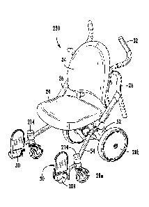
with each other. The first
and second sections may also not even be parallel to each other, in some
embodiments. The multiple
clamps are configured to structurally resist movement of the IV pole with
respect to the frame in six
degrees of freedom.
[0010] The hooks of the IV pole topper may each include a body and an
end, and both the
hook bodies and the hook ends may be arranged to define a periphery of a
circle that is coaxial with a
longitudinal extent of the IV pole.
[0011] The medical device may include a seat and a back rest supported on
the frame so that
a patient may sit thereon and be transported to different locations.
[0012] The information conveyed by the different colored, or otherwise
differently configured,
IV pole toppers may relate to an occupant of the seat of the medical device.
The information may
alternatively, or additionally, relate to a location within a medical
facility. The information may relate to
still other aspects, as well.
[0013] Before the many embodiments of the invention are explained in
detail, it is to be
understood that the invention is not limited to the details of operation or to
the details of construction
and the arrangement of the components set forth in the following description
or illustrated in the
drawings. The invention may be implemented in various other embodiments and of
being practiced or
being carried out in alternative ways not expressly disclosed herein. Also, it
is to be understood that the
phraseology and terminology used herein are for the purpose of description and
should not be regarded
as limiting. The use of "including" and "comprising" and variations thereof is
meant to encompass the
items listed thereafter and equivalents thereof as well as additional items
and equivalents thereof.
Further, enumeration may be used in the description of various embodiments.
Unless otherwise
expressly stated, the use of enumeration should not be construed as limiting
the invention to any
specific order or number of components. Nor should the use of enumeration be
construed as excluding
CA 02857135 2014-05-27
WO 2013/078481 PCT/US2012/066609
3
from the scope of the invention any additional steps or components that might
be combined with or into
the enumerated steps or components.
BRIEF DESCRIPTION OF THE DRAWINGS
[0014] FIG. 1 is a rear elevational view of a wheeled transport chair
according to a first
embodiment;
[0015] FIG. 2 is a side, elevational view of the wheeled transport chair
of FIG. 1;
[0016] FIG. 3 is a front, elevational view of the wheeled transport chair
of FIG. 1;
[0017] FIG. 4 is a perspective view of a wheeled transport chair
according to a second
embodiment;
[0018] FIG. 5 is a side, elevational view of the transport chair of FIG.
4;
[0019] FIG. 6 is a front, elevational view of the transport chair of FIG.
4;
[0020] FIG. 7 is a plan view of the transport chair of FIG. 4;
[0021] FIG. 8 is a bottom, perspective view of the transport chair of
FIG. 4;
[0022] FIG. 9 is a perspective view of the transport chair of FIG. 4
shown with the foot rests
pivoted to a retracted, stowed position;
[0023] FIG. 10 is a perspective view of the transport chair of FIG. 4
shown with one foot rest
pivoted to the forward use position and the other foot rest pivoted to a
backward stowed position;
[0024] FIG. 11 is a side, elevational view of a third embodiment of a
wheeled transport chair
showing an armrest in a use position;
[0025] FIG. 12 is a side, elevational view of the transport chair of FIG.
11 shown with the
armrest in a stowed or retracted position;
[0026] FIG. 13 is an exploded perspective view of the armrest pivoting
mechanism of the chair
of FIGS. 11 and 12;
[0027] FIG. 14 is a close up, perspective view of the cross bar to which
the armrests of FIGS.
11-13 attach;
[0028] FIG. 15 is a close up, perspective view of the armrest pivoting
mechanism that
attaches to the cross bar of FIG. 14;
[0029] FIG. 16 is an exploded, perspective view of a second embodiment of
an armrest
pivoting mechanism;
[0030] FIG. 17 is a side, elevational view of the armrest pivoting
mechanism of FIG. 16 shown
with the armrest pivoted down to a use position;
[0031] FIG. 17A is an enlarged view of the pivoting region of FIG. 17;
[0032] FIG. 18 is a side, elevational view of the armrest pivoting
mechanism of FIG. 16 shown
with the armrest up to a stowed position;
CA 02857135 2014-05-27
WO 2013/078481 PCT/US2012/066609
4
[0033] FIG. 19 is a front perspective view of the end cap of the pivoting
mechanism of FIG.
16;
[0034] FIG. 20 is a rear perspective view of the end cap of FIG. 19;
[0035] FIG. 21 is rear perspective view of a fourth embodiment of a
wheeled transport chair
showing an oxygen bottle that is in the process of being inserted into an
oxygen bottle holder on the
chair;
[0036] FIG. 22 is a rear perspective view of the embodiment of FIG. 21
showing the oxygen
bottle being inserted to a greater extent into the oxygen bottle holder than
that shown in FIG. 21;
[0037] FIG. 23 is a rear perspective view of the embodiment of FIG. 21
showing the oxygen
bottle completed inserted into the oxygen bottle holder;
[0038] FIG. 24 is a perspective view of a top portion of the oxygen
bottle holder of FIGS. 21-
23 that is shown in a locked position;
[0039] FIG. 25 is a perspective view of the top portion of the bottle
holder of FIG. 24 showing
the top portion in an unlocked position;
[0040] FIG. 26 is a perspective, exploded view of an alternative
embodiment of a top portion
of the oxygen bottle holder;
[0041] FIG. 27 is a perspective view of the oxygen bottle holder portion
of FIG. 26 shown with
its fingers in a retracted position;
[0042] FIG. 28 is a perspective view of the oxygen bottle holder portion
of FIG. 26 shown with
its fingers in an extended position;
[0043] FIG. 29A is a side, elevational view of a transport chair
according to a fifth embodiment
showing an alternative construction of a top portion of the oxygen bottle
holder;
[0044] FIG. 29B is a side, elevational view of the transport chair of
FIG. 29A showing the top
portion of the oxygen bottle holder raised to a position enabling the oxygen
bottle to be removed;
[0045] FIG. 30A is a rear view of the transport chair of FIG. 29A showing
the top portion of the
oxygen bottle holder in the lowered position;
[0046] FIG. 30B is a rear view of the transport chair of FIG. 30A showing
the top portion of the
oxygen bottle holder in the raised position;
[0047] FIG. 31 is rear, elevational view of the wheeled transport chair
of FIG. 11 shown with a
brake pedal pressed;
[0048] FIG. 32 is a side, elevational view of the transport chair of FIG.
31 showing one rear
wheel in phantom in order to better illustrate some of the braking structure;
[0049] FIG. 33 is a perspective, exploded view of the braking system of
the chair of FIG. 31;
CA 02857135 2014-05-27
WO 2013/078481 PCT/US2012/066609
[0050] FIG. 34 is a close up perspective, exploded view of the braking
system of the chair of
FIG. 31;
[0051] FIG. 35 is an exploded perspective view of an alternative braking
system that may be
used in any of the transport chair embodiments disclosed herein;
[0052] FIG. 36 is a close up perspective view of some of the components
of the braking
system of FIG. 35;
[0053] FIG. 37 is perspective view of the underside of the braking system
of FIG. 35 shown
coupled to a transport chair;
[0054] FIG. 38 is a side, elevational view of some of the braking system
components of FIG.
35 showing the brakes in a disengaged state;
[0055] FIG. 39 is a side, elevational view of the braking components of
FIG. 38 showing the
brakes in an engaged state;
[0056] FIG. 40 is a perspective view of the braking disc and collar of
the braking structure of
FIG. 35;
[0057] FIG. 41 is a side, elevational view of the pedals of FIG. 35
showing the brake pedal
pressed;
[0058] FIG. 42 is a side, elevational view of the pedals of FIG. 41
showing the go pedal
pressed;
[0059] FIG. 43 is an exploded perspective view of a first embodiment of a
pivot mechanism for
the footrests that may be used in any of the transport chairs disclosed
herein;
[0060] FIG. 44 is an exploded perspective view of the pivot mechanism of
FIG. 43;
[0061] FIG. 45 is a perspective view of the lock insert of FIG. 44
showing an underside of the
lock insert;
[0062] FIG. 46 is a perspective view of a first embodiment of an IV pole
topper;
[0063] FIG. 47 is a perspective view of a second embodiment of an IV pole
topper;
[0064] FIG. 48 is a perspective view of the IV pole topper of FIG. 47, an
IV pole, and a pair of
clamps used to secure the IV pole to the transport chair;
[0065] FIG. 49 is a close-up, perspective view of the clamps and IV pole
of FIG. 48;
[0066] FIG. 50 is a sectional view of the clamps, IV pole, and handlebar
of FIG. 48;
[0067] FIG. 51 is a side, elevational view of the transport chair of FIG.
29A showing a calf rest
extension that is in a retracted position and that may be included in any of
the transport chair
embodiments disclosed herein;
[0068] FIG. 52 is a side, elevational view of the transport chair of FIG.
51 showing the calf rest
extension in an extended position;
CA 02857135 2014-05-27
WO 2013/078481 PCT/US2012/066609
6
[0069] FIG. 53 is a side, elevational view of the calf rest extension of
FIG. 51 shown with the
handle in an un-pulled position;
[0070] FIG. 54 is a side, elevational view of the calf rest extension of
FIG. 53 shown with the
handle in a pulled position;
[0071] FIG. 55 is a perspective, exploded view of several of the
components of the calf rest
extension of FIGS. 51-53;
[0072] FIG. 56 is another perspective, exploded view of several of the
components of the calf
rest extension of FIGS. 51-53;
[0073] FIG. 57 is a sectional view of the locking mechanism of the calf
rest extension of FIGS.
51-53 illustrating the locking mechanism in a locked position;
[0074] FIG. 58 is a sectional view of the locking mechanism of FIG. 57
illustrating the locking
mechanism in an unlocked position;
[0075] FIG. 59 is a perspective, exploded view of several other
components of the locking
mechanism of FIGS. 51-53;
[0076] FIG. 60 is a side, sectional view of the upper portion of the calf
rest showing the calf
support in a generally horizontal orientation;
[0077] FIG. 61 is a side, sectional view of the upper portion of the calf
rest showing the calf
support in a pivoted orientation;
[0078] FIG. 62 is a plan view of a pair of transport chairs illustrating
the nesting ability of the
transport chairs;
[0079] FIG. 63 is a side, elevational view of the chairs of FIG. 62;
[0080] FIG. 64 is a front perspective view of the chairs of FIG. 62;
[0081] FIG. 65 is a rear perspective view of the chairs of FIG. 62;
[0082] FIG. 66 is a side, elevational view of the bottom portion of a
transport chair having a
rear wheelie set; and
[0083] FIG. 67 is an exploded perspective view illustrating the
construction of the wheelie set
of FIG. 66.
DETAILED DESCRIPTION OF THE EMBODIMENTS
[0084] A transport chair 20 according to a first embodiment of the
invention is depicted in
FIGS. 1-3. Transport chair 20 is adapted to allow a patient to be transported
to different locations within
a healthcare facility, such as, but not limited to a hospital, nursing home,
doctor's office, or similar
location. A number of different embodiments of transport chair 20 are
described below and in the
accompanying drawings. It will be understood that further variations of the
embodiments described
herein and shown in the accompanying drawings may be made without departing
from the principles
CA 02857135 2014-05-27
WO 2013/078481 PCT/US2012/066609
7
disclosed herein. It will also be understood that the wheeled transport chairs
described herein include
multiple innovative aspects and features, and that any one or more of these
aspects and/or features
may be combined together with any one or more of the other aspects or
features, or that any one of
these aspects or features may be used alone. For example, the following
description includes a
discussion of a variety of different features, including armrests, footrests,
brakes, an oxygen bottle
holder, an IV pole, a chart holder, a calf rest, and other features. Any one
of these features may be
incorporated into a transport chair by itself. Alternatively, multiple of
these features may be
incorporated into a single transport chair in any desirable combination. Still
further, several of these
features may be used in other applications besides transport chairs,
including, for example, the IV pole
and IV pole topper, the oxygen bottle holder, and the brakes. Such other
applications include, but are
not limited to, wheeled medical devices, or other types of medical devices.
[0085] Although much of the description herein uses the term "transport
chair" to refer to chair
20, as well as its various embodiments, it will be understood that the various
embodiments and
inventions described herein are equally applicable to wheelchairs, in addition
to transport chairs. The
term "wheeled chair" will be used herein as a generic term that encompasses
both wheelchairs and
transport chairs. In general, wheelchairs differ from transport chairs in that
wheelchairs include rear
wheels that are large enough for a patient to grasp and use to move herself or
himself, while transport
chairs tend to have smaller wheels that generally preclude a patient from
propelling herself or himself in
the chair, but instead require a caregiver to push or pull the patient while
seated in the chair.
[0086] The transport chair 20 depicted in FIGS. 1-3 includes a frame 22,
a seat 24 supported
thereon, a pair of armrests 26, a plurality of wheels 28 (that include front
wheels 28a and rear wheels
28b), at least one footrest 30, a pair of handles 32, a back rest 34, and an
IV pole 36. Transport chair
20 further includes a chart holder bottom portion 38, a chart holder top
portion 40, and an oxygen
holder bottom portion 42. While not shown in the embodiment depicted in FIGS.
1-3, but described
elsewhere (e.g. in, and with reference to, FIGS. 4-10 and 31-44), transport
chair 20 may also include a
brake pedal, a stop pedal, an additional footrest, and an oxygen bottle
holder. Still other features may
also be added to transport chair 20.
[0087] Seat 24 provides a top surface 48 on which a patient may sit while
being transported
on transport chair 20. Seat 24 includes a front edge 44 (FIG. 2) and a pair of
side edges 46a and 46b
(FIG. 3). Seat 24 may be cushioned, or it may be substantially rigid, or it
may provide a support for a
separate cushion (not shown) to be placed on top of top surface 48. Seat 24 is
supported above a
cross bar 50 of frame 22. Cross bar 50 extends laterally between a pair of
rear legs 52 of frame 22.
As will be discussed in greater detail below, cross bar 50 generally defines a
horizontal pivot axis about
which armrests 26 may pivot.
CA 02857135 2014-05-27
WO 2013/078481 PCT/US2012/066609
8
[0088] Each rear leg 52 is fastened to a corresponding forward leg 54
that extends forwardly
underneath seat 24. When viewed from either side, rear legs 52 and forward
legs 54 cross each other
in an X-fashion. That is, rear legs 52 extend upwardly and forwardly from rear
wheels 28b to positions
underneath seat 24 where rear legs 52 provide support for the seat 24, while
forward legs 54 extend
downwardly and forwardly from behind seat 24 to termini adjacent the front end
62 of chair 20. The
crisscrossing arrangement of rear and forward legs 52 and 54 generally defines
an X-shape. At each of
the termini of forward legs 54, front wheels 28a and footrests 30 are attached
and supported. At each
of the upper ends of rear legs 52, a seat bracket 68 is attached to which seat
24 is coupled (see FIGS.
8 and 67).
[0089] Forward legs 54 include a lower portion 56 and an upper portion 58.
Back rest 34 is
attached to the upper portion 58 of forward legs 54. Back rest 34 provides a
surface against which a
patient may rest his or her back while seated on transport chair 20. Back rest
34 may itself be
cushioned, or it may be rigid, or it may provide support for a separate
cushion that is attached thereto
(not shown).
[0090] In the embodiment shown in FIGS. 1-3, forward legs 54 of frame 22
terminate at their
upper ends as handles 32. Handles 32 provide a structure which a caregiver can
grip in order to push
and steer transport chair 20. It will be understood that handles 32 could
alternatively be separate
structures from legs 54 that are attached to legs 54, or that are attached to
any other suitable structure
in transport chair 20, in any suitable fashion. In one embodiment, handles 32
include a gripping
material added thereto that resists sliding contact between a person's hand
and the gripping material so
that a caregiver's hands are less likely to slip when pushing or pulling
transport chair 20 via handles 32.
In another embodiment, handles 32 do not have any material added.
[0091] As shown in FIG. 3, lower portions 56 of forward legs 54 are
angled outwardly from
each other as they extend from a rear end 60 to a front end 62 of transport
chair 20. As will be
described in greater detail below, this angling of lower portions 56 creates a
greater space D4 between
front wheels 28a than the lateral spacing D3 between rear wheels 28b (FIG. 3).
This greater spacing
provides a greater space for a patient to stand in front of chair 20, as well
as providing space for
transport chair 20 to nest with another similar transport chair 20 when the
two chairs 20 are being
stored. This greater space in the front of transport chair 20 enables a
patient to stand, turn, and move
around while positioned in front of chair 20 with less likelihood of bumping
into footrests 30, and with a
greater range of available movement, thereby facilitating the entry into, and
exiting from, transport chair
20. Further, the nesting ability of chair 20 reduces the space occupied by
multiple chairs 20 when they
are not in use. Such nesting is shown in FIGS. 62-65 for an alternative
embodiment of the transport
chair, as will be discussed in greater detail below.
CA 02857135 2014-05-27
WO 2013/078481 PCT/US2012/066609
9
[0092] Chair 20 in FIGS. 1-3 is shown holding an oxygen bottle 66 that
may be necessary for
a person being transported in chair 20. If the patient being transported is
not in need of oxygen, then
bottle 66 may be removed from transport chair 20. When chair 20 is used to
transport a bottle 66, it
may attach to an oxygen bottle holder that includes the bottom portion 42 that
holds the bottom of the
oxygen bottle 66 and a top portion (not shown in FIGS. 1-3) that secures a top
region of the bottle 66.
The bottom portion may be positioned close to the floor and have a relatively
shallow depth so that a
caregiver does not have to lift the bottle 66 (which can be heavy) as much as
with prior oxygen bottle
holders in order to place the bottle 66 in the bottom portion 42 of the
holder. The top portion may take
on a variety of different configurations, as will be discussed more below.
Both the top and bottom
portions are discussed in greater detail below.
[0093] IV pole 36 includes a generally vertical rod 70 that is attached
at its lower end to the
upper portion 58 of one of the forward legs 54 via an IV pole bracket 72 (FIG.
1). The upper end of IV
pole 36 includes a IV pole topper 74 that defines a plurality of hooks 76 on
which IV bags, or other
medical equipment, may be hung (see also FIGS 46-47). IV pole topper 74 is
generally circularly
shaped (when viewed from above or below) and each hook 76 is arcuately shaped
so as to define the
periphery of the circular shape of IV pole topper 74. Rather than extending
radially outward from the
generally vertical axis defined by rod 70¨as many prior art IV hooks have
done¨each hook 76
extends circularly around the periphery of topper 74. This configuration leads
to no outward extending
hooks 76 that can be inadvertently bumped against by a caregiver or other
person standing next to
transport chair 20. Because the height of topper 74 is often at or near a
common height of people's
heads (when standing), any outwardly projecting hooks¨such as in the prior
art¨can create potentially
painful projections when bumped against a person's head. In contrast, the
hooks 76 of the IV pole 36
shown in FIGS. 1-3 do not extend outwardly, and therefore do not create any
projections which can be
bumped against from an angle that is directly aligned with the angle of the
projection. Instead, any
bumps against hooks 76 will be sideways and/or glancing, thereby minimizing
the impact of such
bumps. Topper 74 and hooks 76 therefore help to mitigate the seriousness of
any injury that might
otherwise arise from a person bumping their head, or other body part, against
hooks 76.
[0094] While FIGS. 1-3 illustrate an IV pole topper 74 having three
arcuately shaped hooks
76, the construction of IV pole topper 74 may be modified. For example, FIG.
47 shows one alternative
embodiment of an IV pole topper 274 that may be attached to transport chair
20, or to any of the other
transport chair embodiments discussed herein. IV pole topper 274 includes five
arcuate hooks. Still
other numbers of hooks 76 may be included in IV pole topper 274. Further, the
shape of IV pole
toppers 74 and/or 274 may be changed from that shown to any other shapes that
reduce the likelihood
of any hooks 76 pointing directly toward a person who might make inadvertent
contact with the hooks.
CA 02857135 2014-05-27
WO 2013/078481 PCT/US2012/066609
For example, hooks 76 could point radially inward toward the center of IV pole
topper 74 or 274. Other
constructions are also possible.
[0095] As noted above, transport 20 may also include a chart holder for
carrying one or more
patient's medical charts, or for carrying a binder, or for carrying papers, or
any combination of these
items. The configuration of the chart holder may vary, as will be described in
greater detail below. In
the embodiment shown in FIGS. 1-3, the chart holder includes a bottom portion
38 on which the chart
and/or papers may rest. The top portion 40 prevents the charts and/or papers
from tipping out of the
bottom portion. The top portion is defined by a bent bar 80 that extends
between upper portions 58 of
forward legs 54 behind back rest 34. Bent bar 80 is bent in such a way so as
to define an opening 82
(FIG. 1) between bar 80 and the back of back rest 34. A chart, binder, or set
of papers may be inserted
into opening 82 until the bottom of the chart, binder, or papers rests against
bottom portion 38 of the
chart holder. The vertical distance between the bottom portion 38 and the top
portion 40 of the chart
holder is dimensioned such that it is smaller than the height and/or width of
conventional papers. Thus,
when the chart, binder, or papers rest on bottom portion 38, the top end of
the chart, binder, or papers
will extend higher than bent bar 80. Bent bar 80 will thus prevent the chart,
binder, or papers from
tipping off of bottom portion 38. In some embodiments, a clip or other
fastening structure may be
included that grips the chart, binder, or papers. Such a clip may be
particularly useful for flexible items
that could potentially bend or fold out of the opening 82 while still seated
on bottom portion 38, such as
individual sheets of papers, or small quantities of paper, or other flexible
items.
[0096] A transport chair 220 according to another embodiment of the
invention is shown in
FIGS. 4-10. Those components of transport chair 220 that are the same as those
of transport chair 20
are labeled with the same reference numbers, and the description of those
components applies equally
to transport chair 220. Those components of transport chair 220 that are
similar to, but include
modifications, to corresponding components on transport chair 20 will be
referenced by the same
reference number raised by 200. Those components of transport chair 220 that
do not have an
analogue in transport chair 20 will bear a new reference number. It will
further be understood that
transport chair 220 may be modified to exclude any of its components that are
lacking from chair 20,
and/or it may be modified to include any of the components of chair 20 that it
is shown to lack in FIGS.
4-10.
[0097] Transport chair 220 is similar to transport chair 20 but, as
shown, does not include any
chart holder components, an oxygen bottle holder, nor an IV pole. Transport
chair 220 further includes
a pair of buttons 214 that are not present in transport chair 20, as well as a
set of wheelies 78
positioned at a bottom end of rear legs 52 of frame 22, as well as other
differences. Buttons 214 may
be pushed vertically downward to automatically cause the immediately adjacent
footrest 30 to pivot
CA 02857135 2014-05-27
WO 2013/078481 PCT/US2012/066609
11
from a use position in front of seat 24 (shown in FIGS. 4-8) to a stowed
position along the sides 46 of
chair 220 (shown in FIG. 9). The construction and function of buttons 214, as
well as the pivoting
mechanism controlled by buttons 214 will be described in greater detail below.
Wheelie set 78 helps
facilitate a caregiver lifting the front end of transport chair 220 when
moving chair 220 over an obstacle,
such as a curb, or other obstruction. Wheelie set 78 also helps prevent over-
tipping of chair 220
backwards, thereby helping to prevent an accidental backward tipping of chair
220 completely over, as
will be discussed more below, particularly with respect to FIGS. 66 and 67.
[0098] Transport chair 220, like transport chair 20, includes a pair of
front wheels 28a that are
spaced apart a lateral distance D4 that is less than the lateral distance D3
between rear wheels 28b.
This creates a more open space in front of seat 24 so that a patient may enter
and exit chair 220 more
easily.
[0099] The detailed construction of various of the components of
transport chairs 20 and 220,
as well as other embodiments of the transport chairs, will be described in
more detail below. These
components include the armrests, the foot rests, the oxygen bottle holder, the
brakes, a calf rest, and
the IV pole and IV pole topper, as well as other components. As was noted
previously, these various
components may be combined together in a single transport chair in any
suitable fashion, or they may
be used individually by themselves within a transport chair.
ARMRESTS
[00100] FIGS. 11-13 depict a third embodiment of a transport chair 420
that includes many of
the same aspects and components as transport chairs 20 and 220. Those
components of transport
chair 420 that are the same as those of transport chair 20 or 220 are labeled
with the same reference
numbers, and the description of those components applies equally to transport
chair 420. Those
components of transport chair 420 that do not have an analogue in transport
chair 20 will bear a new
reference number. It will further be understood that transport chair 420 may
be modified to exclude any
of its components that are lacking from chair 20 or chair 220, and/or it may
be modified to include any
of the components of chair 20 or 220 that it is shown to lack in FIGS. 11-13.
[00101] The armrests 26 of chair 420 may be incorporated into any of the
chair embodiments
described herein, including transport chairs 20 and 220, as well as any of the
transport chairs
subsequently described herein. Armrests 26 each include a support bar 90 and
an arm bar 92. Arm
bar 92 provides the structure that a patient may rest his or her arms on while
seated in seat 24. Arm
bar 92 also provides a structure that a patient may grasp when entering or
exiting seat 24. Support bar
90 connects arm bar 92 to frame 22. Arm bar 92 includes a rear portion 86 and
a forward portion 88.
As shown in FIG. 11, the height (H1) of forward portion 88 is higher than the
height (H2) of rear portion
86. The higher height (H1) of forward portion 88 provides more accessible
support to a patient who is
CA 02857135 2014-05-27
WO 2013/078481 PCT/US2012/066609
12
either entering or exiting chair 420. That is, a patient who is standing, or
nearly standing, is more easily
able to reach the forward portions 88 of armrests 26 while they are standing,
or nearly standing. This
makes it easier for a patient to hold onto forward portions 88 while the
patient is exiting or entering chair
420, or about to exit or enter chair 420. While the specific height (H1) of
forward portion 88 may vary, it
may generally be chosen to be close the median height above ground (for a
given population) of a
person's index finger (or middle finger) when that person is standing and has
his or her arms and hands
hanging downward at his or her sides. This median height varies somewhat for
different populations,
but generally varies little beyond one or two inches. For example, this height
varies no more than a few
inches when looking at human males within the 95th percentile in height as
compared to human females
who are with the 5th percentile for height.
[00102] By positioning the forward portions 88 of armrests 26 at a height
that can typically be
touched by the ends of a patient's fingers while he or she is fully standing,
the patient is able to feel and
make contact with the handles while he or she is still fully upright. This
enables the patient to make a
tactile determination of the position of chair 420 relative to his or her body
while they are fully standing.
When going from a standing-to-sitting position, the patient therefore does not
typically have to begin to
bend prior to determining the location of the chair, thus helping to ensure
that the patient (who may not
be physically adept at supporting themselves in a bent position) aims and
aligns themselves properly
with the seat 24 prior to sitting down. The higher height of the front ends of
armrests 26 also gives
confidence to the patient, and eases his or her transition from merely
touching the handles while
standing to holding them firmly for support during their downward motion into
the chair.
[00103] Still further, during exit from chair 420, the higher height of
forward portions 88 of
armrests 26 enables the patient to continue to hold onto the armrests 26
virtually throughout the entire
sitting-to-standing motion. Indeed, the patient can often continue to push
downward on the forward
portions 88 of the armrests 26 (and thus lift themselves upward) throughout
the entire sitting-to-
standing motion. This substantially eliminates the need for a terminal portion
of the patient's sitting-to-
standing transition to take place without providing any structure on the chair
for the patient to grasp.
This also continues to provide a tactile indication to the patient of the
location of the chair relative to
their body after they have stood up, helping to ensure the patient doesn't
lose his or her balance, and
also helping to remind the patient of his or her proximity to the chair. Still
further, it can help maintain
the patient's balance while he or she is standing in front of the chair 420.
[00104] While the height H2 of rear portion 86 is shown in FIG. 11 as
being defined with
respect to the floor, this has been done primarily for comparison purposes
with the height H1 of forward
portion 88 of armrests 26. In actual practice, the height H2 may be more
beneficially defined with
respect to the top surface 48 of seat 24. That is, the height of rear portion
86 may be chosen be
CA 02857135 2014-05-27
WO 2013/078481 PCT/US2012/066609
13
positioned above seat 24 at a height that corresponds to, or is near, the
median height of a population's
elbows when they are seated on seat 24 and their arms are hanging downward at
their sides. Thus, a
person sitting upright in chair 420 on seat 24 does not need to slouch much,
if at all, in order to rest his
or her elbows on rear portion 86 of armrests 26. This height provides easy
support and comfort for a
person's arms while seated in chair 420.
[00105] As can also be seen in FIG. 11, forward portion 88 of armrests 26
also may extend
forwardly from front edge 44 of seat portion a distance Dl. Distance D1 may be
equal to several
inches, although the precise magnitude of distance D1 can vary. By extending
forwardly from front
edge 44, a patient is more easily able to grasp armrests 26 while standing in
front of chair 420, or while
either beginning to transition from the standing-to-sitting position or
finishing the transition from the
sitting-to-standing position. The patient does not need to reach behind his or
her back to grasp the
armrests. This makes is easier to not only see the armrests, but also to hold
them while standing
upright, or nearly upright. Further, the extra length of armrests 26 provides
a structure for a patient to
support himself or herself while getting close to seat 24. In contrast to
prior art transport chairs with
armrests that extend only as far as the front edge of the seat (or a shorter
distance), the armrests 26 of
chair 420 provide a supportive structure for the patient that does not require
the patient to hunch over,
or angle their arms, to reach armrests 26 while standing. Instead, the patient
can support himself or
herself on armrests 26 while standing completely upright with his or her arms
oriented straight up or
down. This makes it easier for the patient to enter or exit chair 420.
[00106] As shown in FIGS. 11 and 12, armrests 26 may be pivotable between
a use position
(FIG. 11) and a stowed position (FIG. 12). This pivoting enables the armrests
to be moved out of the
way so that a patient may exit or enter seat 24 along either of the sides of
seat 24. The pivoting of
armrests 26 also enables a patient having a girth nearly equal to, or wider
than, the lateral separation of
armrests 26 to fit comfortably on seat 24 without being squeezed between
armrests 26, or prevented
altogether from sitting on seat because of insufficient lateral separation
between armrests 26.
[00107] The pivoting of armrests 26 takes place about a generally
horizontal pivot axis 94 that,
in the illustrated embodiment, is aligned with cross bar 50. Pivot axis 94 is
located at a height less than
the height of seat 24. By being located at a height lower than seat 24, there
is substantially no
structure that inhibits or obstructs a patient from exiting a side of seat 24
when armrest 26 is pivoted to
the stowed position. Thus, as can be seen in FIG. 12, when armrest 26 is
pivoted to the stowed
position, arm bar 92 is completely behind back rest 34 while support bar 90 is
angled such that no
portion of it presents any actual obstruction to a patient exiting seat 24
from the side. Thus, when
armrest 26 is pivoted to the stowed position, chair 420 is configured¨from the
patient's stand point¨
substantially as if no armrest were present. Moving the armrest 26 to the
stowed position therefore
CA 02857135 2014-05-27
WO 2013/078481 PCT/US2012/066609
14
clears any obstacles that might otherwise impede entering or exiting seat 24
from the side. It also
clears any structure that would prevent, or render uncomfortable, a patient
with girth greater than the
lateral distance between armrests 26 from sitting in seat 24.
[00108] Pivot axis 94 is also located at a position that is forward of the
generally vertical plane
defined by back rest 34, as can be seen in FIGS. 11 and 12. By locating pivot
axis 94 forward of the
plane generally defined by back rest 34, the lever arm defined between pivot
axis 94 and the front end
of forward portion 88 is reduced (as compared to a pivot axis that was in line
with back rest 34). This
reduced lever arm distance means that greater downward forces may be safely
applied to forward
portion 88 of armrests 26 than would be possible if pivot axis 94 were
positioned closer to¨or behind¨
the generally vertical plane defined by back rest 34. This, in turn, makes
forward portions 88 more solid
and provides a feeling to the patient of greater strength and stability for
forward portions 88, thereby
giving the patient confidence during entry or exit into seat 24 that he or she
may safely use forward
portions 88 to fully support himself or herself when exiting or entering seat
24.
[00109] Any and all of the transport chair embodiments described herein,
including, but not
limited to, chairs 20 and 220, as well as the subsequently described chairs,
may include the pivotable
armrests 26 described above with respect to FIGS. 11 and 12. That is, any of
the armrests 26 of the
other transport chairs described herein may include armrests 26 that pivot
from a pivot axis defined
below the seat 24 and forward of back rest 34. Further, the armrests 26 of any
of the transport chair
embodiments described herein may include the features of a forward portion 88
that is elevated with
respect to a rear portion 86 of arm bar 92. The pivoting mechanism that
enables armrests 26 to pivot
between the use and the stowed positions may take on any suitable form. One
illustrative embodiment
of a pivoting mechanism is described below with respect to FIGS. 13-15.
Another illustrative
embodiment of a pivoting mechanism is described with respect to FIGS. 16-20.
Still other pivoting
mechanisms may be used for any of the transport chairs described herein.
[00110] FIGS. 13-14 illustrate in greater detail one suitable construction
of a pivoting
mechanism 96 for armrests 26. Pivoting mechanism 96 includes a pair of
bushings 98, a release
handle 100, a cylindrical body 102, a spring 104, a locking pin 106, an end
cap 108, a spring housing
110, and a stop pin 112. Bushings 98 are each dimensioned to fit within
cylindrical body 102. More
specifically, each bushing 98 is dimensioned to fit within a corresponding
channel 114 defined on the
end of cross bar 50 (FIGS. 13 and 14). Bushings 98 facilitate the pivoting
movement of armrest 26
while it pivots about axis 94. A neck portion of release handle 100 fits
within an aperture 116 (FIG. 15)
defined within spring housing 110. The neck portion is attached to locking pin
106 after the neck
portion has been inserted through aperture 116. Spring 104 is cylindrically
shaped and has a diameter
that is greater than the diameter of aperture 116. The diameter of spring 104
is also greater than an
CA 02857135 2014-05-27
WO 2013/078481 PCT/US2012/066609
upper portion 118 of locking pin 106, but less than the diameter of a lower
portion 120 of locking pin
106. Spring 104 thus fits over upper portion 118 but not lower portion 120.
Spring 104 is interposed
between locking pin 106 and an interior of spring housing 110. Spring 104 may
be configured such
that, when armrest 26 is pivoted to the stowed position, spring 104 is
compressed and exerts a force
against locking pin 106 that urges locking pin 106 radially inward toward
pivot axis 94. This urging of
locking pin 106 toward pivot axis 94 will cause locking pin 106 to
automatically slide into an a stop
aperture 122 defined on cross bar 50 when armrest 26 has been pivoted to the
use position. Spring
104 will continue to urge locking pin 106 to remain in stop aperture 122 while
armrest 26 is in the use
position. When locking pin 106 seated inside stop aperture 122, armrest 26 is
prevented from rotating
about pivot axis 94 because cross bar 50 does not rotate, which means that
stop aperture 122 does not
move, nor can armrest 26 while locking pin 106 is inserted in stop aperture
122.
[00111] In order to move armrest 26 to the stowed position, a user must
first pull on release
handle 100 in a direction radially outward from pivot axis 94. Because release
handle 100 is internally
coupled to locking pin 106, this outward radial force will tend to move
locking pin 106 out of stop
aperture 122, provided this outward radial force is of sufficient magnitude to
overcome the spring force
of spring 104, which biases locking pin 106 towards the locked position within
stop aperture 122. Once
locking pin 106 is moved out of stop aperture 122, armrest 26 is free to
rotate to the stowed position.
The pivoting movement of armrest 26 about pivot axis 94 is limited by stop pin
112, which is inserted
into cylindrical body 102 such that a portion of it extends inwardly from the
interior or cylindrical body
102. This inward portion of stop pin 112 may ride in an elongated channel 124
(FIG. 14) defined within
cross bar 50. The ends of this elongated channel 124 define the forward and
rearward limits of the
pivoting motion of armrest 26. When stop pin 112 reaches one end of this
elongated channel 124,
armrest 26 is prevented from further rotation in a clockwise direction, and
when stop pin 112 reaches
the other end of elongated channel 124, armrest 26 is prevented from further
rotation in a
counterclockwise direction.
[00112] When armrest 26 is moved to the use position (FIG. 11), spring 104
will automatically
push locking pin 106 into aperture 122 defined in cross bar 50. Consequently,
when a user pushes
armrests 26 to their use position, armrests 26 will each automatically return
to their locked state. In this
locked state, neither armrest 26 can pivot unless a user pulls on release
handle 100. Because of this, a
user can lift up on either or both of armrests 26 without causing the armrests
to pivot with respect to
cross bar 50. The armrests can therefore be used either by the patient or the
caregiver to exert an
upward force on the transport chair. Such upward forces may be the result of a
patient attempting to
reposition himself or herself on seat 24, such as by pulling himself or
herself forward, or such forces
may be the result of a caregiver attempting to partially lift, or otherwise
reposition, the transport chair.
CA 02857135 2014-05-27
WO 2013/078481 PCT/US2012/066609
16
Regardless of the purpose of the forces, when armrests 26 are locked in the
use position, they are not
movable in any upward, downward, or sideways directions, thereby providing a
solid and useful
structure for grasping for the patient to use as a support during ingress or
egress, as well as a solid and
useful structure for a caregiver to grasp to hold or to move the transport
chair.
[00113] FIGS. 16-20 illustrate an alternative construction of a pivoting
mechanism 196 that may
be used with transport chair 420, and/or with any of the other transport chair
embodiments described
herein. Pivoting mechanism 196 includes cylindrical body 102 attached to, or
integrated into, the
bottom end of support bar 90. Pivoting mechanism 196 further includes a
bushing 98, a release handle
100, a spring housing 110, a spring 104, a locking pin 106, a stop pin 112,
and an end cap 108.
Pivoting mechanism 196 operates in substantially the same manner as pivoting
mechanism 96. That
is, a user pulls on release handle 100 radially outwardly from the horizontal
pivot axis 94 defined by
cross bar 50 in order to allow armrest 26 to pivot. This outward movement of
handle 100 pulls locking
pin 106 out of stop aperture 122 in cross bar 50, thereby enabling armrest 26
to pivot. The pivoting
movement of armrest 26 is limited by stop pin 112 engaging the ends of
elongated aperture 124. When
armrest 26 is in the use position, stop pin 112 engages a bottom end 111 of
elongated aperture 124
(FIGS. 17 and 17A). When armrest 26 is moved the stowed position, the upward
pivoting of armrest 26
is stopped when stop pin 112 engages a top end 113 of elongated aperture 124
(FIG. 18). Further, due
to the biasing of spring 104, pin 106 is continually urged radially inwardly
toward pivot axis 94, so that
when armrest 26 is returned to the use position, pin 106 will automatically be
inserted back into
aperture 122 of cross bar 50, thereby preventing further pivoting of armrest
26 in the absence of a user
pulling on release handle 100 again. Both bushing 98 and end cap 108 will
rotate with armrest 26 as it
pivots.
[00114] End cap 108 of FIGS. 16-18 is shown in more detail in FIGS. 19 and
20. End cap 108
acts as both an end cap that prevents dirt and unwanted environment debris
from entering pivoting
mechanism 196, as well as a bushing. More specifically, end cap 108 includes
an interior surface 300
(FIG. 20) that engages an exterior surface 302 of cross bar 50. When armrest
26 pivots, interior
surface 300 slides along exterior surface 302 of cross bar 50. End cap 108
further includes a plurality
of flexible fingers 304 that each include a cam surface 306 and a shoulder
308. Cam surface 306
engages an interior surface 310 of cylindrical body 102 (FIG. 16) that has an
interior diameter slightly
less than the exterior diameter of the collectively plurality of flexible
fingers 304. Consequently, when
end cap 108 is pushed inwardly into cylindrical body 102, flexible fingers 304
flex radially inwardly due
to the engage of cam surfaces 306 with interior surface 320. This inward
flexing continues as end cap
108 is pushed further and further into cylindrical body.
CA 02857135 2014-05-27
WO 2013/078481 PCT/US2012/066609
17
[00115] When end cap 108 is pushed fully into cylindrical body 102,
flexible fingers 304 will
reach a groove 312 defined in interior surface 310 (FIG. 16). Groove 312 is
dimensioned to allow
flexible fingers 304 to return to their unflexed stated. In this unflexed
stated, shoulders 308 of flexible
fingers 304 will engage an edge of groove 312, thereby preventing end cap 108
from being pulled out
of cylindrical body 102. Only if each flexible finger is manually engaged and
flexed inwardly so that
shoulders 308 disengage from the edge of groove 312 can end cap 108 be removed
from cylindrical
body 102. However, after cylindrical body 102 and end cap 108 are both mounted
to cross bar 50, the
exterior surface 302 of cross bar 50 has a diameter sufficiently large to
prevent any inward flexing of
flexible fingers 304. Consequently, when end cap 108 and cylindrical body 102
are mounted to cross
bar 50, it is impossible to remove end cap 108 without breaking end cap 108.
Only if cylindrical body
102 is removed from cross bar 50 (by unscrewing stop pin 112 and pulling on
release handle 100, is it
theoretically possible to remove end cap 108 from cylindrical body 102 (by
manually flexing fingers 304
in the manner described above). End cap 108 thereby forms both a permanent end
cap, as well as a
bushing for pivoting mechanism 196.
[00116] It will be understood by those skilled in the art that pivoting
mechanisms 96 and 196
may be varied substantially from that disclosed herein. It will also be
understood that the location of
pivoting mechanisms 96, 196 and/or the release for the pivoting mechanism 96,
196 may be moved to
different locations on the transport chair. For example, the release for
pivoting mechanism 96,196 may
be moved to be positioned anywhere along support bar 90, or at any location
along arm bar 92. When
positioned on arm bar 92, the release for pivoting mechanism 96, 196 may be
positioned on an
underside of arm bar 92 so as to not interfere with a patient resting his or
her arms on armrests 26, yet
still be accessible to a seated patient so that he or she may pivot the arms
to the stowed position, if
desired.
[00117] Transport chair 420, or any of the other transport chair
embodiments described herein,
may also be configured such that the lateral distance D2 (FIG. 3) between
armrests 26 may be
increased or decreased. This variable lateral distance allows chair 420 to be
more comfortably used
with patients of different size. In order to change the lateral distance
between armrests 26, a release
mechanism (not shown) may be included anywhere on armrests 26, or near cross
bar 50. Indeed, in
one embodiment, the release mechanism may be triggered by the same release
handle 100 used to
enable the armrests to pivot about axis 94. The extension and/or retraction of
armrests 26 toward and
away from the center of seat 24 (thereby varying distance D2) may be
accomplished in a variety of
different manners. In one embodiment, cylindrical portion 102 may have its
length along axis 94
extended in the direction of axis 94 so that it overlaps a greater portion of
cross bar 50 when the
armrests are positioned as close as possible to each other (i.e. distance D2
is at a minimum). The
CA 02857135 2014-05-27
WO 2013/078481 PCT/US2012/066609
18
overlapping portion may then be selectively reduced by sliding cylindrical
portion 102 outwardly along
axis 94 so that distance D2 increases. Armrests 26 may then be supported at
different lateral spacings
from each other by having different amounts of cylindrical portion 102 overlap
cross bar 50.
Alternatively, cylindrical body 102 could be dimensioned to have a diameter
smaller than the diameter
of cross bar 50 so that body 102 fit within cross bar 50 and cross bar 50
overlapped variable amounts
of cylindrical body 102. Still other manners of changing the distance D2 could
also be used.
OXYGEN BOTTLE HOLDER
[00118] FIGS. 21-23 illustrate another embodiment of a transport chair 620
according to
various aspects of the invention. Transport chair 620 is similar to transport
chairs 20, 220, and 420 but,
as shown, does not include any chart holder components, any footrests, any
wheelies, or any IV pole.
Those components of transport chair 620 that are the same as those of
transport chairs 20, 220, or 420
are labeled with the same reference numbers, and the description of those
components applies equally
to transport chair 620. It will be understood that wheeled transport chair 620
may be modified to
exclude any its components that are lacking from chairs 20, 220, or 420,
and/or it may be modified to
include any of the components of chairs 20, 220, or 420 that are shown lacking
in FIGS. 21-23.
[00119] Transport chair 620 includes an oxygen bottle holder 130 that
includes an upper
portion 132 and a lower portion 42. Lower portion 42 includes a base or body
134 in which is defined a
circular recess. The circular recess has a diameter that is slightly larger
than the diameter or most
conventional oxygen bottles 66 so that the bottom end of the oxygen bottle 66
can be inserted into the
recess. As shown in FIGS. 21-23, base 134 is positioned close to the floor so
that a caregiver does not
have to lift the oxygen bottle 66 very high in order to position its bottom
end within the circular recess.
Further, the height (H) of base 134 (see FIG. 23) may be relatively small so
that the height which a
caregiver has to lift the bottle 66 to insert it into base 134 is reduced.
Indeed, in one embodiment, the
depth of the circular recess may be insufficient to prevent bottle 66 from
tipping out of the circular
recess without the additional stabilization and/or locking forces provided by
upper portion 132 of bottle
holder 130, which will be described in more detail below. In another
embodiment, such as that shown
in FIGS. 29A-29B, the height H the circular recess defined in base 134 is
sufficiently tall such that an
oxygen bottle 66 positioned therein will not tip out of the base 134, even in
the absence of the oxygen
bottle being secured by upper portion 132 of bottle holder 130. An example of
an oxygen bottle being
held on the transport chair solely by way of base 134 is shown in FIG. 29B. In
the embodiments shown
in FIGS. 21-23 and 29A-29B, the height H is smaller at a rear end of base 134
than at a forward end of
base 134. This helps a caregiver insert the bottle 66 more easily into the
circular recess defined in
base 134 than if the height of the circular recess were uniform throughout its
entire circumference.
CA 02857135 2014-05-27
WO 2013/078481 PCT/US2012/066609
19
[00120] Upper portion 132 of bottle holder 130 may take on a variety of
different configurations.
A first embodiment is shown in FIGS. 21-25, a second embodiment is shown in
FIGS. 26-28, and a
third embodiment is shown in FIGS. 29A-30B. Still other embodiments are
possible.
[00121] In the embodiment of FIGS. 21-25, upper portion 132 includes a
clamp 140 having an
arcuate body or housing 142 in which a pair of slideable arcuate fingers 144
are housed. Arcuate
fingers 144 are shown more clearly in FIGS. 12 and 13. In FIG. 12, fingers 144
are shown in the
extended position, which corresponds to the position in which a bottle 66 may
be secured to transport
chair 620. In FIG. 25, fingers 144 are shown in the retracted position, which
corresponds to the position
in which a bottle 66 may either be inserted between fingers 144 or removed
from between fingers 144.
[00122] In the embodiments shown in FIGS. 21-25, each finger 144 includes
a stop shoulder
146, a toothed surface 148, and a low friction member 150. The toothed surface
interacts with, and
engages, a gear 152 that is rotatably secured within housing or body 142. As
fingers 144 extend into,
or retract out of, housing 142, toothed surfaces 148 engage gear 152, causing
gear 152 to rotate.
Because both toothed surfaces engage gear 152, any movement of one finger 144
either into or out of
housing 142 automatically causes a corresponding similar movement of the other
finger 144. That is,
both arms retract into, or extend out of, housing 142 in unison. This uniform
movement occurs even if
an external extension or retraction force is applied to only one of the
fingers 144. The retraction of
movable fingers 144 into housing 142 is terminated when stop shoulders 146
engage against stops 154
within housing 142.
[00123] A spring 156 is positioned between portions of each finger 144, as
shown in FIGS. 24
and 25. Spring 156 urges each finger to the extended position shown in FIG.
24. Thus, when fingers
are retracted into housing 142, a force must be applied to one or both of
fingers 144 that is greater than
the biasing force of spring 156.
[00124] Low friction members 150 are, in the embodiment shown, rollers
that may rotate about
an axis 158 that is generally vertical in FIGS. 24 and 25. Low friction
members 150 may take on other
forms. Low friction members 150, when configured as rollers, are configured to
rollingly interact with
the exterior surface of bottle 66 when bottle 66 is inserted into upper
portion 132. The movement of a
bottle into upper portion 132 of bottle holder 130 is shown sequentially in
FIGS. 21-23. In FIG. 21, the
base of the bottle 66 is placed in lower portion 42 of bottle holder 130 and
the upper portion of the
bottle 66 is positioned to abut against rollers 150. The caregiver then pushes
the bottle 66 against
rollers 150, which causes a force to be exerted on the ends of movable fingers
144 that tends to retract
the fingers into housing 142. As the fingers begin to retract, the horizontal
separation S between the
ends of fingers 144 (FIG. 22) begins to increase. FIG. 22 shows the bottle
pushed almost all of the way
into the space between fingers 144. Rollers 150 help to reduce the frictional
resistance of bottle 66
CA 02857135 2014-05-27
WO 2013/078481 PCT/US2012/066609
against fingers 144 as bottle 66 is inserted into upper portion 132. Rollers
150 also acts as low friction
cams that help to translate the movement of the bottle 66 toward upper portion
132 into a finger
retracting movement that widens the separation between the ends of fingers
144.
[00125] Once the ends of fingers 144 have been forced apart far enough to
accommodate the
full diameter of bottle 66, any further movement of bottle 66 toward upper
portion 132 will allow the
fingers 144 to extend out of housing 142. That is, once the bottle 66 is
positioned within upper portion
132, the force of spring 156 will force fingers 144 out of housing 142 back to
their extended (and bottle
locking) position. Any outward forces exerted by the bottle against the
interior of fingers 144 will not
result in any retraction of the fingers 144 into housing 142. Instead, fingers
144 will not move against
such outward forces applied to bottle 66. Bottle 66 will therefore be securely
held within the arcuate
interior region defined by arcuate fingers 144 (FIG. 23).
[00126] Because of the configuration of upper portion 132 of bottle holder
130 in the
embodiments shown in FIGS. 21-25, it is not necessary for a caregiver, or
other person, to directly
touch any of upper portion 132 when pushing a bottle 66 thereinto. That is,
the person does not need
to grasp either finger 144, or any other portion of upper portion 132 in order
to secure a bottle therein.
Instead, the person may simply hold onto bottle 66 and push the bottle toward
upper portion 132. This
pushing force will cause fingers 144 to initially retract until the bottle
fits between the fingers.
Thereafter, the force of spring 156 will return fingers 144 to their extended
and locked position. A
caregiver, or other person, therefore can keep both hands on bottle 66 while
securing it to chair 420,
and does not need to release one hand in order to manipulate upper portion
132. Because of the
weight of bottles 66, this makes it easy to secure it to chair 420 while
retaining full control of bottle 66
with two hands.
[00127] In order to remove a bottle from bottle holder 130, a caregiver or
other person may
grasp either one of movable fingers 144 and push them in a direction that
causes them to retract into
housing 142. Once sufficiently retracted, the top portion of bottle 66 may be
tipped out of the reach of
fingers 144 while the bottom portion of the bottle 66 remains in the circular
recess of base 134. Once
out of the reach of fingers 144, the person may then freely lift the bottle 66
out of the base 134.
[00128] Upper portion 132 of bottle holder 130 may be secured to chair 420
by way of a bar
160 that is secured to a bracket 162 attached to the upper portion 58 of one
of the forward legs 54 of
frame 22, as shown in FIGS. 21-23.
[00129] FIGS. 26-28 illustrate an alternative embodiment of bottle holder
130. More
particularly, FIGS. 26-28 illustrate an alternative embodiment of an upper
portion 132' of bottle holder
130. Those components of upper portion 132' that are the same as those found
in upper portion 132
are labeled herein with the same reference numbers. Those components of upper
portion 132' that are
CA 02857135 2014-05-27
WO 2013/078481 PCT/US2012/066609
21
similar to components in upper portion 132 but have been changed in some
fashion have been given
the same reference number followed by the prime symbol 0. Components in upper
portion 132' that
are not found in upper portion 132 have been given a new number.
[00130] Upper portion 132' differs from upper portion 132 in that upper
portion 132' includes a
trigger 136 that automatically extends fingers 144' when a user inserts an
oxygen bottle into upper
portion 132'. Trigger 136 is visible in FIGS. 26-28 and intersects a channel
138 in which one of fingers
144' slides. Trigger 136 includes a trigger pin 164 defined therein. A trigger
spring 170 is disposed
between trigger 136 and an inner surface of body 142'. Trigger spring 170 is
adapted to exert a biasing
force that urges trigger 136, and its attached trigger pin 164, outward toward
the position shown in FIG.
27. When in this outward position, trigger pin 164 engages a slot 171 defined
in one of fingers 144'.
This engagement prevents the finger 144' from extending outward into the
extended position shown in
FIG. 28. However, when a user inserts the top portion of an oxygen bottle into
upper portion 132' and
presses the bottle against trigger 136, the force applied by the user to
trigger 136 will overcome the
biasing force of trigger spring 170, thereby allowing trigger 136 and trigger
pin 164 to slide inwardly
(toward spring 170) until pin 164 disengages from slot 171. When pin 164
disengages from slot 171,
the biasing force of spring 156 will automatically urge fingers 144' to the
outward configuration in the
manner discussed above with respect to upper portion 132.
[00131] When a person wishes to remove the oxygen bottle from upper
portion 132', he or she
simply manually pushes on either or both of fingers 144' in a direction that
urges the fingers 144' toward
their retracted positions. By applying sufficient force to overcome the
biasing of spring 156, fingers 144'
will retract into body 142'. As one of fingers 144' retracts, an angled
surface 169 will urge pin 164
inward, forcing trigger 136 to compress trigger spring 170. Angled surface 169
will continue to urge pin
164 inward until pin 164 reaches slot 171, at which point trigger spring 170
will urge pin 164 into slot
171, which will retain fingers 144' in their retracted positions (provided the
top portion of the oxygen
bottle has been removed sufficiently from upper portion 132' so as to provide
clearance for trigger 136
extending outwardly).
[00132] Upper portion 132' therefore provides a convenient tool for easily
inserting an oxygen
bottle therein without requiring a user to manually manipulate fingers 144'
prior to inserting the oxygen
bottle therein. This frees the user's hands, thereby enabling him or her to
use both of their hands for
holding the bottle and/or for other purposes while positioning the bottle in
holder 130. Trigger 136
therefore provides an automatic gripping or locking feature that automatically
locks or grips the upper
end of the oxygen when it is inserted into upper portion 132'. The amount of
force necessary to
activate trigger 136 can be made relatively low because trigger spring 170
exerts a force that does not
directly prevent the extension of fingers 144'. In other words, trigger spring
170 exerts a force that is
CA 02857135 2014-05-27
WO 2013/078481 PCT/US2012/066609
22
generally perpendicular to the movement of the adjacent finger 144', and it is
the physical blocking
action of pin 164 that resists the extension of fingers 144', not the force of
spring 170. Therefore,
trigger spring 170 can be configured such that relatively little force is
necessary to overcome it so that a
user inserting an oxygen bottle into upper portion 132' does not detrimentally
notice the extra force
necessary to compress spring 170.
[00133] As was noted, the finger 144' adjacent to trigger 136 includes an
angled surface 169
that urges trigger 136 toward spring 170 when the finger 144' is pushed
inwardly to its retracted
position. Angled surface 169 also allows spring 170 to extend toward a more
extended position while
fingers 144' are in their extended position. Thus, trigger spring 170 is never
left to remain in the fully
compressed state (or the state where it is compressed enough to release finger
144'). This helps to
reduce fatigue of spring 170 and ensure that spring 170 will always have
sufficient resilience to urge pin
164 back into slot 171, even after long periods of use or non-use, including
long periods of repetitive
use and non-use.
[00134] FIGS. 29A-30B illustrate another alternative embodiment of a
bottle holder 330 that
may be used on any of the transport chairs discussed herein. Bottle holder 330
includes a base 134
that is, in one version, the same as base 134 of bottle holder 130. Bottle
holder 330 further includes an
upper portion 332 that is modified from the upper portions 132 and 132' of
bottle holder 130. More
specifically, upper portion 332 includes a movable arm 166 that is pivotable
between a locked position
(FIGS. 29A, 30A) and an unlocked position (FIGS. 29B, 30B). Movable arm 166
pivots between the
locked and unlocked positions by a user grasping the arm 166 and either
raising it or lowering it. When
in the raised (unlocked) position of FIGS. 29B and 30B, a user may either
insert a bottle 66 into upper
portion 332, or remove a bottle 66 therefrom. When in the lowered (locked)
position of FIGS. 29A and
30A, the arm 166 prevents the bottle 66 from being moved into or out of the
upper portion 332.
[00135] Movable arm 166 may include a latching mechanism positioned
adjacent its free end
that releasably interacts with a stationary end 168 of upper portion 332 (FIG.
30B). The latching
mechanism can be a magnet that magnetically couples to a magnet positioned on
stationary end 168 to
releasably hold movable arm 166 in the lowered position. Alternatively, the
latching mechanism can be
a pin that fits into a hole, wherein one of the pin and hole is defined on one
of arm 166 and stationary
end 168, and the other of the pin and hole is defined on the other of the arm
166 and stationary end
168. Other latching mechanisms may also be used, such as, but not limited to,
hook and loop type
fasteners (e.g. Velcro), snaps, or other types of structures.
[00136] Movable arm 166 pivots about a pivot axis 334 (FIG. 29A) that is
angled with respect to
horizontal. More specifically, pivot axis 334 slopes downwardly toward the
ground in the front-to-back
direction. This downward angle of pivot axis 334 helps provide clearance for
movable arm 166 when it
CA 02857135 2014-05-27
WO 2013/078481 PCT/US2012/066609
23
is raised or lowered while bottle 66 is present so that arm 166's range of
motion will not be blocked by
bottle 66. Additional clearance is also provided by the shape of movable arm
166. Rather than being
curved in an arcuate shape of a constant radius, movable arm 166 is
constructed to be curved in a
manner wherein the radius of curvature is varied. More specifically, and as
can be better seen in FIG.
29B, movable arm includes a first curved section 336 closest to pivot axis 334
and a second curved
section 338 that is positioned closer to the free end of movable arm 166.
First curved section 336 has a
smaller radius of curvature than second curved section 338. This difference in
curvature may be
defined by way of discrete differences, i.e. there may be a total of two
different radii (or another discrete
number of different radii), or this difference in curvature may be continuous,
i.e. there may be radii that
continuously vary. Whether discrete or continuous (or combinations thereof),
the different radii of
curvature help to ensure that movable arm 166 is not prevented from moving to
the locked position
when a bottle 66 is held by holder 330.
[00137] It will be understood by those skilled in the art that, although
bottle holders 130 and
330 have been described herein as being used for holding an oxygen bottle, any
bottle or other
structure¨whether containing oxygen or some other substance¨that are desirably
transported with a
patient on a transport chair may be secured to the transport chair by way of
bottle holders 130 or 330.
It will also be understood that, although trigger 136 has been described
herein only in conjunction with
upper portion 132', trigger 136 could also be adapted to be used with upper
portion 332. When so
adapted, upper portion 332 would include one or more springs, or other
devices, that automatically
lowered movable arm 166 into the downward, or locked position, (e.g. FIG. 28B)
when a user inserted
the upper end of an oxygen bottle into upper portion 332. Further, one or more
additional springs, or
other devices, could be added that¨after movable arm 166 was manually lifted
to the raised, or
unlocked position¨retained movable arm in this raised position until such time
as a user inserted
another bottle into upper portion 332 and thereby once again activated the
trigger 136. Still other
variations are possible.
BRAKE AND RELEASE PEDALS
[00138] FIGS. 31-34 illustrate in greater detail a braking system 172
that, as illustrated, is
incorporated into transport chair 420. It will be understood that braking
system 172 is not limited to
being used with transport chair 420, but instead can be incorporated into any
of the different transport
chair embodiments disclosed herein. FIGS. 35-42 illustrate in detail an
alternative brake system 372
that also may be used on any of the transport chairs described herein,
including, but not limited to, chair
420. It will also be understood that braking systems 172 and 372 can be used
on other medical
devices besides transport chairs and wheelchairs, such as, but not limited to,
cots, stretchers, beds,
gurneys, or any other medical device having wheels that are desirably braked
and unbraked.
CA 02857135 2014-05-27
WO 2013/078481 PCT/US2012/066609
24
[00139] Transport chair 420 includes a brake pedal 126 and a release or go
pedal 128 (FIGS.
31-34). Brake pedal 126 prevents rear wheels 28b from rotating when brake
pedal 126 is pressed.
Pressing release or go pedal 128 causes the brake pedal 126 to be released,
and thereby allows rear
wheels 28b to freely rotate. Front wheels 28a, in the illustrated embodiments,
are casters that are both
freely rotatable and freely swivelable at all times. In some embodiments,
however, brake pedal 126
also activates brakes on front wheels 28a so that all four wheels 28 are
braked. In such cases, release
pedal 128 will release all four brakes when it is pressed.
[00140] FIGS. 31-34 illustrate one manner of constructing brake system
172. Brake system
172 is constructed using a pin-and-slot type of arrangement wherein a pin is
inserted into a slot in order
brake wheels 28b and removed therefrom in order to allow rotation of wheels
28b. It will be understood
by those skilled in the art, however, that different types of brake systems
172 may be used, such as, but
not limited to, drum brakes, disc brakes, other types of frictional brakes,
and/or still other types of
brakes.
[00141] As best seen in FIGS. 33 and 34, brake system 172 includes a pair
of toothed wheels
174, a pair of screws 176, a pair of bushings 178, a pair of brake pin links
180, a pair of springs 182, a
pair of stationary mounting brackets 184, a brake rod 186, a pair of torsion
springs 188, a pair of
shoulder bolts 190, a spring pin 192, and a brake link 194. Spring pin 192
secures brake rod 186 within
a pair of brake link apertures 195 defined at the lower ends of rear legs 52.
Spring pin 192 connects
brake rod 186 to legs 52 in a non-rotational manner. That is, brake rod 186
does not rotate, but instead
remains in a fixed position. Brake link 194 is rotatably secured to mounting
brackets 184 by screws 176
that are inserted through bushings 178 and link apertures 198 defined at each
end of brake link 194.
Screws 176 further extend into apertures 200 defined in mounting brackets 184.
Apertures 200 may be
internally threaded to threadingly receive screws 176 and secure screws 176 to
mounting brackets 184.
Screws 176 further extend through brake link apertures 202 defined in each
brake pin link 180. This
connection allows brake pin links 180 to rotate about a generally horizontal
pivot axis that is aligned
with the longitudinal extent of screws 176.
[00142] Each brake pin link 180 includes a brake pin 204 on its outward
side that selectively fits
between pairs of teeth on toothed wheels 174 in order to selectively brake
chair 420. Springs 182 each
bias brake pin links 180 such that each brake pin 204 is urged radially toward
the rotational axis 206 of
rear wheels 28b. Thus, each spring 182 urges each brake pin 204 towards a
braking position. When
brake pedal 126 is pressed, it enables each brake pin link 180 to rotate such
that spring 182 is free to
insert a brake pin 204 defined on each brake pin link 180 between the nearest
pair of teeth on toothed
wheels 174. The downward movement of brake pedal 126 does not force brake pin
204 into the space
between pairs of teeth on toothed wheels 174. Instead, the force of springs
182 urges pin 204 into
CA 02857135 2014-05-27
WO 2013/078481 PCT/US2012/066609
these inter-teeth spaces. Thus, if transport chair 420 is positioned such that
brake pins 204 are not
precisely aligned with a space between teeth on toothed wheels 174, it is not
necessary for a caregiver
to supply sufficient force to move chair 420 slightly (which may be difficult
due to the weight of the
patient, and/or the transport chair being positioned on an incline) in order
to change the alignment of
pins 204 with toothed wheels 174. Instead, this force is supplied by springs
182 and, if pins 204 are not
precisely aligned with the spaces between teeth on wheels 174, any slight
rolling of chair 420 will bring
about an alignment of pins 204 with the inter-tooth spaces on wheels 174, at
which point springs 182
will insert the pins 204 between the teeth, thereby braking chair 420. Such
rolling movement does not
need to occur immediately at the time of pressing brake pedal 126, but may
occur at any time after
brake pedal 126 is pressed. As soon as such movement occurs, pins 204 will be
urged by springs 182
into spaces between the teeth on wheel 174, thereby locking wheels 28b and
preventing any further
movement.
[00143] Brake system 172 therefore avoids the requirement that a user must
press down on
brake pedal 126 with sufficient force to urge pins 204 between the teeth on
wheel 174. As a result, the
amount of force necessary to push down on brake pedal 126 is the same,
regardless of whether pins
204 are aligned with spaces between the teeth on wheel 174 or not. This gives
the user of the transport
chair a consistent feel when using brake pedal 126. It also avoids the problem
of some prior art
toothed-wheel-and-pin braking systems where, depending upon the relative
position of the pin and
toothed wheel when the brakes are applied, the user may have to apply an
enormous force to activate
the brakes in some cases, and may only have to apply a small force in other
cases.
[00144] Pressing release pedal 128 will rotate brake rod 186 and brake pin
links 180 such that
pins 204 are moved out of engagement with toothed wheel 174, thereby allowing
rear wheels 28b to
freely rotate. The pressing of release pedal 128 and rotation of brake pin
links 180 will overcome the
spring forces exerted by springs 182 such that pins 204 are able to move out
of engagement with
toothed wheel 174. Generally speaking, a portion of the energy expended by the
user in fully pushing
release pedal 128 down will be devoted to stretching springs 182, which will
therefore store this energy
as potential energy that is later used to urge the pins 204 back into
engagement with toothed wheels
174 when brake pedal 126 is later pressed. Release pedal 128, when pressed,
will remain in the
pressed condition by way of a slot (not shown) defined on the underside of
release pedal 128.
Similarly, brake pedal 126 will remain in the pressed condition when pressed
by way of a slot (not
shown) defined on the underside of brake pedal 126. Torsion springs 188 each
urge brake pedal 126
and release pedal 128 toward their upward positions so that, when one pedal is
pressed, the other is
released (i.e. moved upward). Thus, pressing brake pedal 126 will cause
release pedal 128 to be
CA 02857135 2014-05-27
WO 2013/078481 PCT/US2012/066609
26
released (i.e. moved upward). Similarly, pressing release pedal 128 will cause
brake pedal 126 to be
released.
[00145] As noted, brake system 172 is configured such that at least some of
the energy
required to press release pedal 128 is stored as potential energy in springs
182. This potential energy
remains stored in springs 182 until a user presses brake pedal 126. Upon
pressing brake pedal 126,
the movement of brake rod 186 and brake pin links 180 allows springs 182 to
pull brake pins 204 into
locked engagement with toothed wheels 174, thereby releasing the potential
energy. Such potential
energy is therefore stored while the chair is free to be pushed, and released
when braked.
[00146] FIGS. 35-42 illustrate an alternative brake system 372 that may be
used on any of the
transport chair embodiments discussed herein. Brake system 372, like brake
system 172, includes a
brake pedal 126 and a go pedal 128, and pressing on brake pedal 126 prevents
rotation of rear wheels
28b. Further, pressing on go pedal 128 automatically causes the release of
brake pedal 126, thereby
enabling rear wheels 28b to freely rotate. Brake system 372, like brake system
172, is based upon a
toothed gear and pin system, although brake system 372 uses multiple sets of
pins, unlike brake
system 172. Brake system 372 differs from brake system 172 in that, among
other things, brake
system 372 is contained within rearward legs 52 of frame 22. Legs 52 thereby
provide a housing for
brake system 372 that helps shield it from dirt, dust, and other contaminants,
as well as providing a
more visually pleasing exterior. Further, rearward legs prevent objects from
getting caught in the
toothed gears, and other components, of brake system 372. The detailed
construction of brake system
372 will now be described.
[00147] In addition to go pedal 128 and brake pedal 126, brake system 372
further includes a
pair of bearing covers 374, a brake shaft 376, a toggle shaft 378, a toggle
link 380, a pair of wheel
shafts 382, a plurality of roller bearings 384, and a pair of brake gear
assemblies 386. Toggle shaft 378
and toggle link 380 operate to pivot upwardly one or the other of brake pedal
126 and go pedal 128.
That is, toggle shaft 378 and toggle link 380 toggle the up and down pressing
of pedals 126 and 128 so
that only one of these pedals can ever be pressed at a given moment. Pressing
on the pedal that is
currently raised will cause that pedal to lower while simultaneously causing
the other pedal to release
(move upward). This toggling action is accomplished through an upper pin 388
and a lower pin 390
defined on toggle link 380.
[00148] As can more easily be seen in FIGS. 41 and 42, toggle link is
rotatable about the pivot
axis defined by toggle shaft 378. In the braked position shown in FIG. 41,
lower pin 390 is position at a
location lower than the pivot axis of toggle shaft 378. When a user presses on
the go pedal, the
downward force exerted by the user on the go pedal is transferred to upper pin
388, which in turn
causes link 380 to rotate clockwise (in FIGS. 41 and 42). This clockwise
rotation causes lower pin 390
CA 02857135 2014-05-27
WO 2013/078481 PCT/US2012/066609
27
to move upwardly, thereby causing brake pedal 126 to move upwardly and thereby
release the brake
(in a manner to be described below). Brake pedal 126 and go pedal 128 are held
in either the up or
down configuration by way of a pair of springs, brake cam link assemblies, and
a brake cam spring
pads that are contained within each brake gear assembly 386, as will be
discussed in greater detail
below.
[00149] As can be seen more clearly in FIGS. 36 and 38-39, each brake gear
assembly 386
includes a plurality of components that are positioned inside of each
respective rear leg 52 of frame 22.
These components include a pair of brake fingers 392, a toothed wheel 394, a
brake cam 396, a brake
cam link assembly 398, a spring 400, and a brake cam spring pad 402. Each
brake finger 392 is
pivotable about a brake finger pivot axis 404. Further, each brake finger 392
includes a braking pin 406
that has a longitudinal axis that extends out of the plane of FIGS. 38 and 39.
When the transport chair
is in the braked condition, one of the braking pins 406 from each set of brake
fingers 392 will be
positioned in one of the slots defined in toothed wheel 394. As shown in FIG.
39, which illustrates
brake gear assembly 386 in the braked position, the braking pin 406 from the
left brake finger 392 is
positioned between a pair of teeth defined on toothed wheel 394. Toothed wheel
394 is fixedly
attached to wheel shaft 382 such that, when toothed wheel 394 is prevented
from rotating (by way of a
pin 406), wheel shaft 382 is also prevented from rotating. Still further,
wheel shaft 382 is fixedly
attached to one of the rear wheels 28b. Consequently, when a pin 406 prevents
toothed wheel 394
from rotating, the attached rear wheel 28b is also prevented from rotating,
and is thus in a braked
condition.
[00150] As can be seen more clearly in FIGS. 38 and 39, pins 406, brake
fingers 392, and
toothed wheel 394 are constructed such that only a single pin 406 may engage
the teeth of toothed
wheel 394 at any given time. That is, pins 406 are positioned so as to be at
staggered locations with
respect to the spaces between teeth on toothed wheel 394. If one of the pins
406 is contacting the
crest of one of the teeth, and is thus prevented from inserting itself in the
gap between adjacent teeth,
the other of the pins 406 will be positioned between a pair of teeth, and
therefore able to insert itself a
pair of teeth. By having pins 406 oriented in this staggered condition, it
effectively doubles the number
of teeth, thereby reducing the total number of angular orientations the rear
wheels 28b may have where
one of pins 406 is not able to insert itself between a pair of teeth on wheel
394.
[00151] A spring 408 is connected between each set of brake fingers 392
and urges the brake
fingers 392 toward each other. This urging also urges the brake pins 406
radially toward the center of
toothed wheel 394. When one of the pins 406 is aligned with one of the spaces
between adjacent
teeth, spring 406 will therefore urge that pin 406 into that space and keep
the pin there until a user
presses the go pedal 128. As will be discussed in greater detail below, when a
user steps on go pedal
CA 02857135 2014-05-27
WO 2013/078481
PCT/US2012/066609
28
128, fingers 392 are forced apart, causing spring 408 to stretch, and also
causing the one pin 406 that
is lodged in toothed wheel 394 to become dislodged. A person stepping on go
pedal 128 therefore
must press down with sufficient force to stretch spring 408. As a result,
spring 408 will store potential
energy while the go pedal is pressed, and release this energy when the brake
pedal is pressed. The
released energy will cause fingers 392 to pivot toward each other, and one of
pins 406 will become
lodged in toothed wheel 394.
[00152] As
with brake system 172, the user who pushes down on brake pedal 126 does not
directly force any of pins 406 into the slots of toothed wheel 394. This means
that, in those situations
where neither one of pins 406 may not be perfectly aligned with a slot, the
user does not have to push
down on the brake pedal with any additional force in order to force one or
both rear wheels 28b to
rotate a small amount so that one of pins 406 will become aligned with a slot.
Instead, the user pushes
down on the brake pedal 126 with the same amount of force regardless of
whether or not any pins 406
are aligned with the slots on wheel 394. If none are aligned, then the chair
won't be braked until one or
both of the rear wheels 28b rotates sufficiently to allow a pin 406 to enter
one of the slots of toothed
wheel 394. This, however, will happen automatically due to the force applied
by spring 408. Thus, if
the chair does not become completely immobile after brake pedal 126 is
pressed, it will become
completely immobile once one or both of the rear wheels 28b rotate a tiny
amount.
[00153] The
manner by which fingers 392 are forced apart when the go pedal 128 is pressed
can be more easily understood with respect to FIGS. 38-39. Pressing on the go
pedal 128 causes
brake shaft 376 to rotate, as was discussed above. This rotation, in turn,
causes brake cam 396 to
rotate. Brake came 396 includes a cam surface 410 that engages the ends of
brake fingers 392.
Because of the shape of cam surface 410, when brake cam 396 is oriented as
shown in FIG. 38
(unbraked condition), fingers 392 will be forced apart by cam surface 410
sufficiently far so that neither
pin 406 is positioned in a slot of toothed wheel 394. When brake cam 396 is
rotated, however, as
shown in FIG. 39, the shape of cam surface 410 allows fingers 392 to move
closer to each other (as
urged by spring 408), thereby enabling one of pins 406 to enter a slot on
toothed wheel 394.
[00154]
Spring 400, spring pad 402, and brake cam link assembly 394 function to keep
brake
cam 396 in either the braked orientation or the unbraked orientation. That is,
these elements prevent
the brake system from staying in an intermediate position where the system is
neither completely
braked or completely free. When either the brake pedal 126 or the go pedal is
pressed, spring 400 is
compressed, and thus exerts an expansive force against brake cam link assembly
398. This expansive
force will translate into either a clockwise or counterclockwise rotational
force against brake cam 396.
More specifically, when the brakes are engaged, spring 400 will exert a
clockwise force on brake cam
396, as shown in FIG. 39. When the brakes are disengaged, spring 400 will
exert a counterclockwise
CA 02857135 2014-05-27
WO 2013/078481 PCT/US2012/066609
29
force on brake cam 396, as shown in FIG. 38. In either case, the force of
spring 400 will act to resist
toggling of brake and go pedals 126 and 128. A channel 412 defined in each of
the bodies of pedals
126 and 128 will prevent further rotation of brake cam 396 in the direction it
is being urged by spring
400. More specifically, as can be seen in FIGS. 41-42, an upper end 414 of
each channel 412 will
define the amount of allowable rotation of brake cam 396, and will therefore
limit the rotation of brake
cam 396 between the range defined in FIGS. 38 and 39.
[00155] FIG. 40 illustrates in better detail the manner in which each
toothed wheel 394 and
each rear wheel 28b are coupled together. Because the rear wheel 28b is
positioned outside of rear
leg 52, while the toothed wheel 394 is positioned inside of the rear leg 52,
the toothed wheel 394 and
rear wheel 28 cannot be directly attached to each other. Because of this lack
of direct coupling, there is
the potential for an undesirable amount of mechanical slop between the toothed
wheel 394 and the rear
wheel 28b. That is, there is the potential that, while toothed wheel 394 is
prevented from rotating by
one of pins 406, the corresponding rear wheel 28b might be able to rotate a
small amount because of
the indirect coupling of the rear wheels 28b to the toothed wheel. This would
otherwise give the
transport chair an undesirable feel when the brake was activated because each
rear wheel 28b would
still be able to rotate a tiny amount. This would also have the potential for
giving the patient less
confidence in the stability of the chair when he or she was exiting and
entering the chair, in which case
he or she might not place as much force on, or otherwise rely on the stability
of, the transport chair.
This could then make entering and exiting the chair more difficult for the
patient.
[00156] Consequently, it is desirable to reduce the amount of mechanical
slop between the
rear wheels 28b and their corresponding toothed wheels 394. This is
accomplished through several
design features. First, each wheel shaft 382 includes a flat surface 416
defined in the area where
toothed wheel 394 attaches to shaft 382. This flat surface 416 can be seen in
FIGS. 38 and 39. Flat
surface 416 prevents any rotation of shaft 382 that does not also involve a
corresponding amount of
rotation of toothed wheel 394. In other words, were the exterior surface of
shaft 382 completely round
in the area of wheel 394's attachment thereto, it would potentially be
possible for wheel 394 to slip on
shaft 382. Flat surface 416 prevents any such slippage. Further, toothed wheel
394 is tightly coupled
to shaft 382 by way of a collar 418 (FIG. 40) that is secured to toothed wheel
394 by a pair of screws
419, or other suitable fasteners. The tight attachment of toothed wheel 394 to
wheel shaft 382,
including the engagement between flat surface 416 and toothed wheel 394, means
there is very little, if
any, mechanical slop between toothed wheel and shaft 382. That is, when one
rotates, the other
rotates the same amount.
[00157] Rear wheels 28b are coupled to shaft 382 in a manner that also
reduces, or eliminates,
any mechanical slop between the wheels and shaft 382. Shaft 382 includes a
keyed surface 422 that
CA 02857135 2014-05-27
WO 2013/078481 PCT/US2012/066609
tightly engages a complementarily shaped keyed surface defined on the interior
side of each rear wheel
28b (not shown). When a threaded fastener is attached to the threaded end of
shaft 382 (after wheels
28b is attached to shaft 382), the tightening of the threaded fastener urges
the keyed surface of 422
tightly against the corresponding keyed surface of the rear wheel 28b, thereby
reducing or eliminating
any mechanical slop between the rear wheel 28b and shaft 382. As a result,
when toothed wheel 394
is prevented from rotating by a pin 406, rear wheels 28b are also prevented,
and have little, if not any,
freedom of movement. This provides the user and patient with a stable chair,
when braked, to help
facility ingress and egress into and out of the chair.
[00158] It will be understood that various modifications can be made to
brake system 172
and/or brake system 372. For example, while brake system 372 illustrates
spring 408 biasing both pins
406 toward toothed wheel 394, system 172 could be modified to have two
separate springs, or other
biasing mechanisms, so that each pin 408 was biased by its own separate spring
or biasing
mechanism. Brake system 372 could also be modified to include more than two
pins 408 that are
urged into braking engagement between the teeth of wheel 394. By including
more than two pins 408,
the resolution of toothed wheel 394 would be effectively increased, thereby
decreasing the amount of
rotational movement that wheel 394 (and the rear wheel 28b to which it is
coupled) could experience
prior to at least one of the pins 408 lodging itself between teeth when the
brake pedal is pressed. Still
further, the alignment of each of the pair of pins 408 relative to toothed
wheel 394 within a first one of
rear legs 52 could be offset from the alignment of the pair of pins 408
relative to the other toothed
wheel 394 within the second rear leg 52. By making the alignment of pins 408
to their adjacent toothed
wheel 394 different for each rear wheel 28b, the effective resolution of the
toothed wheels is increased
such that, when the brake pedal is pressed, there are more opportunities for
at least one of the pins
408 in one of the rear legs 52 to be aligned an inter-tooth space in its
adjacent wheel 394. This will
result in increasing the probability that, when the brake pedal is pressed, at
least one of the two rear
wheels 28b will immediately lock without any further rotation of the wheels
28b, while the other rear
wheel will thereafter lock when it rotates sufficiently to allow one of its
corresponding pins 408 to insert
itself into the adjacent toothed wheel 394.
[00159] In yet another modification, brake system 372 could be modified so
that both pins 408
are positioned at the same relative orientation to the teeth of wheel 394.
When so positioned, both pins
408 will either be jointly inserted between different pairs of teeth on wheel
394, or they will jointly be out
misaligned with the space between different pairs of teeth on wheel 394.
Although such a modification
would decrease the overall resolution of the slots on the toothed wheel 394,
the use of multiple pins
simultaneously lodged in these slots could provide increased braking strength.
Further, the loss of
CA 02857135 2014-05-27
WO 2013/078481 PCT/US2012/066609
31
resolution could be mitigated by having the pins 408 in one rear leg 52 offset
from the pairs of pins 408
in the other rear leg 52, as discussed above.
[00160] In yet another modification, brake system 172 and/or 372 can be
modified to use different
brake activation and brake de-activation structures than the brake pedal 126
and release pedal 128.
For example, in one embodiment, the control of the brakes is carried out using
hand controls, instead of
foot controls. That is, instead of activating and deactivating the brakes by
pressing on pedals with a
foot, the user activates and deactivates the brakes by manipulating a control
using his or her hands.
Such controls may be positioned at any suitable location on the transport
chair where a user is able to
touch the controls without having to bend over, or otherwise make
uncomfortable movements. As but
one example, handles 32 could include¨or have positioned adjacent thereto¨one
or more buttons,
switches, pivotable members, or other structures that, upon pushing,
switching, or pivoting, activate
and/or deactivate the brakes. The transmission of the movement of these
controls to the area adjacent
rear wheels 28b and toothed wheels 194, 394 could be carried out in any
suitable manner, such as, but
not limited to, one or more Bowden cables. Still other variations are also
possible.
FOOTRESTS
[00161] FIGS. 43-45 illustrate one embodiment of a swing mechanism for
footrests 30. As was
briefly described above, any of the transport chair embodiments described
herein may be equipped with
footrests 30 that automatically pivot from the use position (FIGS. 4-8) to the
stowed position (FIG. 9)
when a user presses on a button 214 (FIGS. 43-44). This automatic pivoting
clears the space in front
of seat 24, thereby providing more space for a patient to enter or exit the
transport chair. The swing
mechanism shown in FIGS. 43-45 may be used on any of the transport chair
embodiments discussed
herein. Alternatively, different swing mechanisms may be used in place of the
specific embodiment
shown in FIGS. 43-45. Still further, in some embodiments, footrests 30 are
configured so that they do
not automatically swing away, but instead require a user to manually push the
footrests 30 into a
stowed position. In still other embodiments, footrests 30 are configured so
that they do not swing or
pivot between a use and stored position at all, but instead remain in the use
position at all times.
[00162] A swing or pivot mechanism 216 is shown in more detail in FIGS. 43
and 44. Swing
mechanism 216 includes button 214, a spring 218, a caster post 219, a push
shaft 222, a lock insert
224, an extend tube 226, a spring bushing 228, a torsion spring 230, a spring
holder 232, and a pin
248. All of these components are positioned inside of, or coupled to, a
cylindrical body portion 250 of
extend tube 226. Spring holder 232 is fixedly coupled to caster post 219.
Spring bushing 228 and
extend tube 226 are fixedly coupled to each other so that they will rotate
with each other when footrest
30 moves between the stowed and use positions. When footrest 30 is in the use
position, rotation of
extend tube 226 is prevented by the position of pin 248 within a main channel
252 defined in lock insert
CA 02857135 2014-05-27
WO 2013/078481 PCT/US2012/066609
32
224. More specifically, lock insert 224, spring bushing 228, are prevented
from rotating with respect to
caster post 219 (which is attached to frame 22) because of the position of pin
248 in channel 252.
When button 214 is pressed downwardly, push shaft 222 is also pushed
downwardly, which in turn
relieves the upward pressure exerted by spring 218 on pin 248 that otherwise
keeps pin 248 lodged in
channel 252 (note: lock insert 224 is shown in FIG. 45 upside down with
respect to its orientation in
FIG. 44). By relieving this pressure, the torsional force of torsion spring
230, which is coupled by way
of spring bushing 228, and cylindrical body 250 to lock insert 224, is
sufficient to overcome the
rotational resistance created by the interaction of pin 248 against a detent
254 defined on lock insert
224. Therefore, lock insert, as well as cylindrical body 250 (and extend tube
226) are free to rotate due
to the force of torsional spring 230. This rotation causes the extend tube
226, to which footrest 30 is
coupled, to pivot to the stowed position. This pivoting motion is slowed by
the frictional engagement of
detent 254 with pin 248. Footrest 30 therefore pivots with a more controlled,
and less jerky movement,
to the stowed position that it otherwise would with detent 254.
[00163] When footrest 30 reaches the stowed position, lock insert 224 will
have rotated
sufficiently far to allow pin 248 to engage a lip 256 defined generally
opposite main channel 252 (FIG.
45). This engagement of lip 256 with pin 248, along with the force exerted by
spring 218, will resist
rotation of footrest 30 out of the stowed position. However, as can be seen in
FIG. 45, lip 256 is
sufficiently sloped such that a person can manually overcome the resistance
offered by the interaction
between lip 256 and pin 248. Therefore, in the absence of any additional user
applied force, footrests
30 will automatically swing to the stowed position after button 214 is pressed
and remain there.
Further, they will remain there unless a force is applied manually by a user
to pivot them back to the
use position. Once in the use position, the force of spring 218 will cause pin
248 to re-lodge itself in
main channel 252, thereby preventing footrests 30 from moving out of the use
position in the absence
of someone pressing the corresponding button 214. A pair of hard stops 258
(FIG. 45) prevent rotation
of footrests 30 beyond the range of motion defined between the use position
and the stowed position.
This range of motion is chosen so that the footrests 30 will not bang into any
portion of frame 22, or any
other portion of the transport chair, when they are automatically pivoted from
the use position to the
stowed position.
[00164] Other than the buttons 214, the automatic swinging of the
footrests 30 from the use
position to the stowed position upon pushing buttons 214 is carried out in a
manner wherein the
components for swinging the footrests 30 are all self-contained within caster
post 219 and cylindrical
body portion 250. Thus, there are no components that stick out, no latches
that need manual re-
positioning, no arms that need to be manually re-adjusted upon one or the
other of the swinging
motions, and no other structures that extend outside the compact and combined
unit of the caster post
CA 02857135 2014-05-27
WO 2013/078481 PCT/US2012/066609
33
219 and the cylindrical body portion 250. Further, the caster posts 219 and
cylindrical body portions
250 are positioned on top of the part of forward legs 54 to which front wheels
28a are attached. The
addition of caster posts 219 and/or cylindrical portion 250 at the front end
of front legs 54 therefore
does not add to the physical footprint of the chair beyond what is already
required for supporting the
front wheels 28a. This means that swinging the footrests 30 between the use
position and the stowed
position does not require additional structures that otherwise clutter the
front area of the transport chair
more than if such swinging abilities were not present. Swinging mechanisms 216
therefore enable
swinging movement of footrests 30 without increasing clutter that would
otherwise hinder patient
ingress and egress to and from the chair.
[00165] It will be understood by those skilled in the art that other types
of triggers for activating the
swinging or pivoting mechanism 216 may be used as an alternative to button
214. Further, the location
of the trigger, whether it includes button 214 or some other type of trigger,
can be changed from being
positioned atop cylindrical body portion 250 to another suitable location.
Still further, in one alternative
embodiment, no triggering mechanism is included and the swinging of footrests
30 between their use
and stowed position is carried out by manually applying forces to the footrest
30, or any component
physically attached thereto, in the direction of either the use position or
the stowed position. In this
manual embodiment, the cylindrical body 250 can include one or more components
that help retain the
footrests in either the use or stowed position, such as one or more detents,
or the like. Such
components will require a person to exert a slightly greater force to
initially move the footrest 30 out of
either the use or stowed position than is required to swing the footrest after
it has become dislodged
from either the use or stowed position. Still other variations are possible.
[00166] In the illustrated embodiments, the swinging of footrests 30
between the use and
stowed positioned takes place about a generally vertical axis 212 (FIGS. 43-
44). As can best be seen
in FIG. 43, generally vertical axis 212 is also the axis about which front
caster wheels 28a swivel. That
is, in the illustrated embodiments, front wheels 28a are caster wheels that
are able to both rotate about
a generally horizontal rotational axis, which allows movement of the chair,
and to swivel about generally
vertical axis 212, which allows swiveling of the caster wheels so that they
may turn in the direction of
movement of the chair. A more compact design is achieved by having both the
swiveling of front
wheels 28a and the swinging of footrests 30 about a common axis 212.
[00167] In addition to the pivoting or swinging of footrests 30 between
the use and stowed
positions, each footrest 30 includes a footrest pan 234 that is pivotable
about a generally horizontal
pivot axis 260 (FIG. 44) between an upright position (shown in FIG. 44) and a
generally flat position (not
shown). In the generally flat position, footrest pan 234 is oriented generally
horizontally so that it
provides a platform on which a user may position his or her feet.
CA 02857135 2014-05-27
WO 2013/078481 PCT/US2012/066609
34
[00168] FIG. 44 illustrates one embodiment of a pivoting assembly 262 that
may be used with
any of the footrests 30 of any of the transport chairs disclosed herein.
Pivoting assembly 262 is
adapted to maintain its associated footrest pan 234 in the upright position
shown in FIG. 44 (as well as
other figures, e.g. FIGS. 4-10) in the absence of a patient positioning his or
her feet thereon. Thus,
when a patient is about to enter seat 24, footrest pans 234 will be oriented
vertically upright, thereby
creating more space for the user to enter seat 24 (assuming the footrests have
been pivoted to the use
position¨even more space will be created if the footrests 30 are kept in the
stowed position until after
the patient enters seat 24). In order to pivot the pans 234 to their
horizontal orientation, the patient lifts
his or her feet and places them on top of the pans 234, forcing them down to
their horizontal
orientation. When it is time for the patient to exit the transport chair, the
patient lifts his or her feet off
of the pans 234, and the pans will automatically pivot upwardly, creating more
clearance in the front
area of the transport chair so that either egress from the chair, or having
the patient rest his or her feet
directly on the ground, is easier.
[00169] Pivoting assembly 262 includes footrest pan 234, a spacer bushing
236, a pair of
bushings 238, a slotted spring holder 240, a torsion spring 242, a spring
housing 244, a pivot cover
246, a pin 264, and a retaining ring 266. Spacer bushing 236, bushings 238,
pan 234, slotted spring
holder 240, torsion spring 242, spring housing 244, and pivot cover 246 are
all coupled to a generally
straight section 268 of extend tube 226. Pin 264 fits into a slot 270 defined
in slotted spring holder 240.
Pin 264 also fits into an aperture 272 defined in straight section 268. Pin
264, as well as slotted spring
holder 240, therefore do not pivot about pivot axis 260. Torsion spring 242 is
coupled at one end to
slotted spring holder 240. The other end of torsion spring 242 is coupled to
spring housing 244, which
in turn is coupled to pan 234. The manner of the coupling between torsion
spring 242 and pan 234 is
such that, when pan 234 is in the upright position, relatively little
torsional force is being exerted by
spring 242 on pan 234. Further, to the extent such a torsional force is being
applied, it is urging pan
234 to remain in the upright position. When a person presses down on pan 234,
they must overcome
the resistance of torsion spring 242. The energy expended in overcoming this
resistance is stored as
potential energy in spring 242 and released when a person removes his or her
feet from pan 234. This
released potential energy is used in rotating pan 234 back to its upright
position.
[00170] By configuring footrests 30 so that they automatically return to
their upright position,
not only does this create greater clearance for the patient, but this also
allows the transport chairs to
nest together. Examples of such nesting are shown in FIGS. 62-65. When the
footrests 30 of a first
transport chair are in their upright position and the first chair is nested
into the back side of a second
chair, the upright position of the footrests 30 of the first chair allow the
first chair to be nested without
having the footrests come into contact with the rear wheels 28b. By
automatically returning the
CA 02857135 2014-05-27
WO 2013/078481 PCT/US2012/066609
footrests to their upright position, a user therefore does not need to
manually alter the configuration of
the footrests prior to nesting one into another, which reduces the amount of
work that would otherwise
be necessary to nest the chairs together.
[00171] As can be seen more clearly in the embodiments shown in FIGS. 43-
44 and 8, each
footrest 30 also includes a pivot extension 208 defined in pivot cover 246.
Pivot extension 208 is
adapted to allow a caregiver to easily use his or her foot to manually flip
the attached footrest 30 from
the upward orientation to the downward orientation. The caregiver can
accomplish this by inserting the
toe of his or her shoe underneath pivot extension 208 while footrest 30 is in
the upright position and
then pivoting his or her shoe upwardly and slightly outwardly (i.e. away from
the footrest 30 on the
opposite side of the chair). This will cause the pivot extension 208 to pivot
upwardly and the footrest
pan 234 to pivot downwardly to the use (e.g. generally horizontal)
orientation. When in this use
position, pivot extension 208 is oriented generally horizontally (see FIG.
52), while when in the stowed
position, pivot extension 208 is oriented generally vertically (FIGS. 43-44).
By being oriented generally
vertically when footrest 30 is in the stowed positioned, pivot extension 208
does not extend outwardly
from footrest 30, and therefore does not create an extra obstruction in this
orientation. Pivot extension
208 provides a convenient structure for enabling a caregiver to move footrests
30 to their lowered
position without requiring the caregiver to bend down and manually manipulate
the footrests 30. Such
manual lowering can assist a patient who is in the process of putting his or
her feet onto footrests 30.
IV POLE AND TOPPERS
[00172] As was noted previously, IV pole 36 includes an IV pole topper
attached to its top end,
such as, but not limited to, the IV pole toppers 74 and/or 274 shown in FIGS.
46 and 47. Each IV pole
topper 74, 274 includes a plurality of hooks 76 on which an IV bag, or other
medical equipment may be
hung. While some transport chair embodiments shown herein do not include an IV
pole 36 attached
thereto, it will be understood by those skilled in the art that such transport
chair embodiments may be
modified to include an IV pole having an IV pole topper. Further, those
embodiments showing an IV
pole 36 may be modified to eliminate the IV pole 36.
[00173] IV pole topper 274 includes an attachment aperture 276 (FIG. 47)
defined in its center
that is adapted to receive a fastener 278 (FIG. 48) that is also received in
the top end of IV pole 36.
The fastener 278 may be any suitable fastener, such as, but not limited to, a
screw or other threaded
fastener. The threads of the fastener 278 matingly engage internal threads
defined in the top end of IV
pole 36 (not shown), to thereby secure IV pole topper 274 to IV pole 36. In
one embodiment, fastener
278 is configured to attach IV pole topper 74 and/or 274 to IV pole 36 such
that the topper 74 and/or
274 is free to rotate about the generally vertical axis defined by the upper
portion of pole 36. In another
CA 02857135 2014-05-27
WO 2013/078481 PCT/US2012/066609
36
embodiment, fastener 278 is configured to rigidly attach IV pole topper 74
and/or 274 to pole 36 such
that the attached topper is not able to rotate about this generally vertical
axis.
[00174] Because IV pole topper 274 is attached to pole 36 by way of a
fastener 278 that fits
into the top of topper 274, fastener 278 is largely invisible to people in the
vicinity of the transport chair.
This is because the IV pole topper 274 is often positioned at a height
generally at, or above, the normal
eye level of a standing person. Thus, unless a person is positioned above the
generally horizontal
plane defined by topper 274, he or she will not see fastener 278 positioned in
aperture 276. That is,
fastener 278 is not visible from any vantage points at or below the horizontal
plane defined by the main
body of topper 274.
[00175] IV pole topper 274 is, in some embodiments, colored in a manner
that signifies
information to a caregiver. In some embodiments, topper 274 is a uniform
color. In other
embodiments, topper 274 may be multi-colored. Regardless of whether it is
single or multi-colored, the
color of topper 274 can be used to provide information to caregivers in a
healthcare facility where there
are multiple transport chairs. For example, a healthcare facility may choose
to have all of its transport
chairs that are assigned to a specific floor of a building, or a specific
department of the facility, a first
color, while all of its transport chairs that assigned to a different floor or
department are given a different
color. This provides an easy visual indication to caregivers of where the
transport chair is to be
returned to if it is moved to a different location. Further, owners of the
transport chair can easily change
the assignment of a particular transport chair by replacing the topper 274
with one of a different color.
[00176] Alternatively, the color or colors toppers 274 may be used to
provide visual information
about one or more aspects of the patient assigned to that chair. For example,
one particular color of
toppers 274 may be used to indicate that the patient assigned thereto is an
infection risk, or that the
patient assigned thereto is not an infection risk. In other embodiments, the
color may indicate the
language spoken by a particular patient, whether the chair is clean or in need
of cleaning, or it may
indicate medical information about the particular patient, such as, but not
limited to, allergies, fall risks,
medication information, whether the patient is blind, whether the patient is
deaf, or any other useful
classification where a visual indicator is helpful to the caregivers, staff,
or other individuals who use the
transport chair. Still other categories of patient information may be
indicated by the colors of toppers
274 (or 74).
[00177] The different colored toppers 74, 274 may be made available to
users of the transport
chairs in a variety of different manners. In one manner, the customer who is
purchasing the transport
chair orders different colored toppers 74, 274 from the manufacturer of the
transport chair during the
initial purchase of the transport chair. In an alternative manner, the
customer may separately order
toppers 74, 274 in the desired colors subsequent to the initial transport
purchase, either from the
CA 02857135 2014-05-27
WO 2013/078481 PCT/US2012/066609
37
manufacturer of the transport chair, and/or from designated dealers who are
authorized by the
manufacturer of the transport chair. In still other manners, colored toppers
74, 274 may be available for
purchase or lease from third parties that have no affiliation with the
manufacturer of the transport chair.
[00178] In still other embodiments, IV pole 36 may be used with other
objects besides toppers
74, 274 to indicate any of the above-mentioned information. That is, different
types of toppers may be
used that do not provide IV hooks for hanging IV bags. Such toppers may be
configured and designed
in any manner. In some embodiments, such toppers serve only to indicate
information, and do not
provide any other functionality. In other embodiments, such as with toppers
74, 274, the toppers are
configured to indicate information and to provide an additional function, such
as providing hooks for IV
bags. When the toppers are used to visually convey information, such toppers,
for example, may act in
the same manner as a flag that indicates information. Indeed, in some
embodiments, the toppers are
flags, and such flags may be made of flexible material or more rigid material.
In other embodiments,
the toppers are configured to hold paper on which symbols or words can be
written or printed. In still
other embodiments, the toppers include other types of writing surfaces (e.g.
whiteboard-type surfaces,
or other types of surfaces) built therein on which messages or other
indications may be written.
[00179] When used to provide information to caregivers, the toppers to IV
pole 36 may be
configured in different manners from that of toppers 74, 274. That is, the
topper may be of a
conventional hook configuration that is color coded, or otherwise altered or
configured in some manner
to provide information. Such alterations or configuration may include changes
to the shape of all or a
portion of the topper. Such changes or configurations can be implemented in a
manner that is visually
apparent to caregivers not only while they are positioned next to the
transport chair to which the IV pole
36 is attached, but also from greater distances, such as the distances the
caregivers may encounter in
their work environment (e.g. the lengths of hallways, corridors, etc.)
[00180] In summary, a variety of different types of toppers¨whether
configured like toppers 74,
274 or otherwise¨may be used to create a system of visual communication that
provides caregivers
information about the patient in the transport chair, or the transport chair
itself. It will be understood
that, in still other embodiments, this system of visual communication can be
applied to other medical
devices besides transport chairs. For example, toppers 74, 274, and all of the
variations discussed
herein, may be used with beds, stretchers, operating tables, cots, or other
devices that support and/or
transport patients. In still other embodiments, this system may be applied to
medical devices that are
used to treat patients, such as ventilators, pumps, dialysis machines, and
other medical devices. As
discussed above, when the toppers are applied to non-transport chair medical
devices, the toppers may
be configured like toppers 74 and/or 274, or they may be differently
configured, including, but not
limited to, configurations that do not provide any hooks or support for IV
bags.
CA 02857135 2014-05-27
WO 2013/078481 PCT/US2012/066609
38
[00181] FIGS. 48 and 49 illustrate one manner in which IV pole 36 may be
attached to frame
22 of a transport chair. As shown, a plurality of clamps 280 are used to
secure IV pole 36 to one of the
forward legs 54 of frame 22. More specifically, in the region of the forward
leg 54 where IV pole 36 is
secured, forward leg 54 includes a first section 282 and a second section 284.
First and second
sections 282 and 284 are angled with respect to each other. One of clamps 280
is attached to first
section 282 and IV pole 36, while the other of clamps 280 is attached to
second section 284 and IV
pole 36. Because first and second sections 282 and 284 are angled with respect
to each other, a more
secure attachment of IV pole 36 to forward leg 54, and thus the entire
transport chair, is effected. The
reasons for this are explained below.
[00182] Often times a caregiver or other user of the transport chair will
push or pull on the chair
by grasping IV pole 36 instead of handles 32. When the person does this, they
may exert a significant
amount of force on IV pole 36 and the clamps 280 used to secure pole 36 to the
transport chair. This
applied force can itself be significant and/or this applied force can be, and
often is, amplified by the
lever arm distance between the location where the force is applied to pole 36
and the location of the
uppermost clamp 280. For example, FIG. 48 illustrates an applied force F
applied to pole 36 at a
distance D5 from the uppermost clamp 280. Regardless of whether the applied
force itself is
significant, or the multiplicative effect of the lever arm distance is
amplifying the force, the clamp or
clamps 380 need to be able to withstand such forces over time.
[00183] In the past, IV poles have been attached to wheelchairs using only
a single clamp.
When a person pushes, pulls, or otherwise exerts a force on the IV pole, this
has tended to loosen that
clamp, particularly over time. Further, the use of a single clamp only
structurally restrains the IV pole in
four degrees of freedom (forward-backward movement, lateral movement, and
rotations about
perpendicular horizontal axes). Movement in the vertical direction, as well as
rotation about the vertical
axis of the pole, is only frictionally restrained by the clamp, not
structurally restrained. This frictional
restraint can be overcome with time. Further, even the structural restraints
can be loosened over time
due to the magnitude and repetition of the applied forces. The loosening of
the restraints (structural,
frictional, or both) can happen even if multiple clamps are used and they are
attached in a collinear
arrangement with respect to each other.
[00184] The clamp arrangement shown in FIGS. 48 and 49 (and elsewhere
herein), however,
overcomes the aforementioned issues and provides structural restraint in all
six degrees of freedom. It
achieves this by using a pair of clamps 280 that are located at different
which are not parallel or aligned
with each other (sections 282 and 284). Each clamp 280 structurally restrains
pole 36 in four degrees
of freedom (forward backward movement, lateral movement, and rotation about
perpendicular
horizontal axes). Further, the combination of the two clamps 280 being
arranged in a non-collinear
CA 02857135 2014-05-27
WO 2013/078481 PCT/US2012/066609
39
fashion structurally restrains both vertical movement and rotation about a
vertical axis defined by the
vertical upper portion of IV pole 36. Rotational movement is structurally
resisted because the two
clamps 280 are not rotationally aligned (they don't have center axes that are
collinear). Vertical
movement is also structurally resisted because at least one, if not both, of
sections 282 and 284 are not
vertically oriented, and their corresponding clamps 280 are also not
vertically oriented. Consequently,
by having angled sections 282 and 284 in leg 54, as well as corresponding
angled sections in IV pole
36 (not separately labeled), and using clamps 280 at each section, a coupling
is achieved between IV
pole 36 that structurally resists any movement in all six degrees of freedom.
This solid coupling helps
to prevent any wiggling over time between pole 36 and the chair, even in the
presence of excessive
forces, and even after such forces are repeated and accumulated over lengthy
periods of time. This
solid coupling also gives the user a robust feeling when grabbing the IV pole
36, and further allows the
user to push and/or pull on the transport chair without causing damage to the
pole 36, or loosening the
connection between the pole 36 and the transport chair.
[00185] As an alternative to arranging clamps 280 in the manner shown in
FIGS. 48 and 49, it
would be possible to achieve a similar level of robustness and structural
restraint in six degrees of
freedom if clamps 280 were parallel, but not collinear, and they were properly
positioned to abut the
bends or elbows in the leg 54. By being parallel but not collinear, rotation
about a vertical axis would be
structurally resisted by the two clamps. Further, by positioning the clamps
280 adjacent the bends or
elbows in leg 54, vertical movement of the IV pole 36 would be prevented by
the bends or elbows
contacting one or both of the clamps 280.
[00186] In addition to its use on transport chairs and wheel chairs, the
clamps 280 and
attachment methods shown and described herein may be used to attach IV poles
36 to other medical
devices, such as, but not limited to, stretchers, beds, cots, surgery tables,
pumps, ventilators, dialysis
equipment, or still other types of medical equipment. By clamping the IV pole
36 to the medical device
at two locations that are not parallel and collinear with respect to each
other¨or that are parallel but not
collinear with each other and the clamps are arranged adjacent the bends or
elbows in the attachment
structure¨the IV pole may be secured in a fashion that structurally resists
motion in all six degrees of
freedom and provides a robust coupling between the medical device and the IV
pole.
[00187] It will also be understood that any of the toppers discussed
herein can be used with a
modified IV pole that is different from IV pole 36. For example, the IV pole
could be modified so that it
was a telescoping pole whose vertical height was adjustable in a telescoping
manner. Thus, if no IV
bag needed to be hung and/or no communication information was desired to be
displayed in a highly
visible manner on the transport chair, or other mobile medical device, the
telescoping IV pole could be
lowered to its lowest height so as to not be an obstruction or obstacle. If an
IV bag were later to be
CA 02857135 2014-05-27
WO 2013/078481 PCT/US2012/066609
hung, or if it were later desired to use the pole for visually displaying
information, the IV pole could then
be extended vertically. The topper could remain on the IV pole in both its
extended and retracted
positions, or it could be removed when the pole was retracted to its lowest
position. Still other
variations of the IV pole could be implemented.
[00188] As was described previously, IV pole toppers 74 and 274 are each
generally circularly
shaped with arcuate hooks 76 defined in, and aligned with, the overall
circular shape of toppers 74 and
274. This configuration not only leads to no outwardly pointing hooks 76 that
could be inadvertently
bumped against, it also leads to no outwardly point extensions, prongs, or
other structures that could
directly come into contact with a person's head, eye, or other body part that
was positioned at the same
height as the topper 74, 274. Toppers 74 and 274 each include a ribbon 84 that
has a top edge 288, a
bottom edge 290, an outer surface 292, and an inner surface 294. Ribbon 84 is
connected to a central
body 296 by way of a plurality of spokes 298. Ribbon 84 is arranged to define
a circular shape in both
toppers 74 and 274. Top edge 288 is continuous around the entire circular
shape of ribbon 84 in both
toppers 74 and 274. Bottom edge 290 is not continuous around the entire
circular shape, but instead is
interrupted several times in areas of ribbon 84 that are adjacent to each hook
76. These interruptions
provide space for a user to insert a loop, or other structure, that is
attached to an IV bag over one of
hooks 76. Hooks 76 themselves are circular and defined within ribbon 84.
[00189] Although ribbon 84 is depicted as circular shaped in FIGS. 46 and
47, it can be
modified to have different shapes in other embodiments. In one alternative
embodiment, ribbon 84 is
shaped as a polygon. When shaped as a polygon, ribbon 84 can include a hook 76
defined on each
side of the polygon. Alternatively, multiple hooks 76 may be defined on each
side of the polygon, or
hooks 76 may be defined in less than all of the polygon sides. Although
changing the shape of ribbon
84 from a circular shape to a polygonal shape will create some vertical edges,
such edges can be
smoothed or blunted, particularly in cases where the polygon is more than
three or four sided. In still
other embodiments, ribbon 84 may be curved in the vertical direction as well
as the horizontal direction,
having, for example, an outer surface 292 that, when traveling vertically
downward from top edge 288
to bottom edge 290, traces a curved path. Other shapes besides curved shapes
may also be used.
[00190] As shown in the accompanying drawings, ribbon 84 is endless in the
sense that it does
not include an end or a beginning. Instead, it forms a complete circle which,
as noted, can be modified
to other shapes. In addition to modifying ribbon 84 to other shapes, ribbon 84
may be modified to not
be endless. As but one example, ribbon 84 could be made of several discrete
sections that are spaced
from each other, but are still each arcuately shaped so that the sections, in
combination, still generally
defined a circle. Still other variations are possible.
CALF RESTS
CA 02857135 2014-05-27
WO 2013/078481 PCT/US2012/066609
41
[00191] In any of the transport chair embodiments disclosed herein, one or
more calf rests 450
may be included. Examples of such calf rests 450 are shown in FIGS. 29A-29B
and 51-61, among
other figures. Calf rests 450 are adapted to support a patient's legs while
sitting in seat 24. Further,
calf rests 450 are adapted to be extendable and retractable between a stowed
position (FIG. 51) and a
use position (FIG. 52). In the embodiments of the transport chair shown in
FIGS. 51-52, there is only
one calf rest shown. However, it will be understood that two calf rests 450
may be incorporated into a
single transport chair, such as is shown in FIGS. 29A and 29B. It will also be
understood that calf rests
450 can be incorporated into other medical devices besides transport chairs,
including, but not limited
to, examination tables, operating tables, or any other patient support
apparatus where it is desirable to
be able to selectively support one or both of a patient's lower legs.
[00192] As shown in more detail in FIGS. 51-61, calf rests 450 include an
inner extrusion 452,
an outer extrusion 454, and a pad assembly 456. Pad assembly 456 includes an
upper surface 458
upon which a patient may rest his or her calf, or leg. Upper surface 458 may
be padded, or it may
provide a surface to which a pad may be fastened. As is shown more clearly in
FIGS. 60 and 61, pad
rest assembly 456 is pivotable about a generally horizontal pivot axis so that
pad rest assembly 456
may be oriented at an angle that generally aligns with the patient's calf.
Further, inner extrusion 452 is
able to translate with respect to outer extrusions 454 in a telescoping
manner¨that is, inner extrusion
452 can slide into, and extend out of, outer extrusion 454.
[00193] When calf rest 450 is in the retracted position, it is retained
therein by way of a locking
mechanism that will be discussed in greater detail below. In order to release
the locking mechanism, a
user pulls on a handle 460 that is coupled to an upper end of inner extrusion
452. Pulling on handle
460 releases the locking mechanism, thereby enabling a user to pull inner
extrusion 452 out of outer
extrusion 454. Once calf rest 450 is pulled to the fully extended use
position, any upward pivoting of
calf rest 450 is resisted by the weight of the patient's calf resting on pad
assembly 456 and any further
downward pivoting is prevented by a suspension linkage 466 coupled between
frame 22 and calf rest
450. In terms of the relative translation of inner extrusion 452 with respect
to outer extrusion 454, such
relative translation is prevented in the extended position because a latch,
such as an outer end 480 of a
peg 474, will be inserted into a use position aperture 522 (FIGS. 55, 56, and
59) defined in the upper
end of outer extrusion 454. That is, when a user has fully translated inner
extrusion 452 out of outer
extrusion 454 and into the extended or use position, and the user releases
handle 460, outer end 480
of peg 474 will be pulled by a spring 476 in such a manner that it will insert
itself into use position
aperture 522, and thereby prevent retraction of calf rest 450 back into the
stowed position. This is
described in greater detail below.
CA 02857135 2014-05-27
WO 2013/078481 PCT/US2012/066609
42
[00194] In order to retract calf rest 450 back to its retracted position, a
user pulls on handle 460
again, which causes peg 474 to be rotated (overcoming the force of spring 476)
out of use position
aperture 522, thereby allowing inner extrusions 452 to translate with respect
to outer extrusion 454.
While still holding handle 460, the user pushes the inner extrusion 452 back
toward the outer extrusion
454. Once fully retracted, the locking mechanism automatically re-engages, and
the calf rest is not able
to extend, nor pivot downwardly, without once again pulling on handle 460.
[00195] The detailed construction of a locking assembly 462 that may be
used with calf rest
450 will now be described with respect to FIGS. 53-58. Locking assembly 462,
in addition to inner and
outer extrusions 452 and 454, further includes an outer bushing 464, a
suspension linkage 466, a lower
pivot bracket 468 that are coupled to outer extrusion 454. Locking assembly
also includes a cassette
470 that is positioned inside of inner extrusion 452, an inner bushing 472,
peg 474, a spring 476, and a
Bowden cable 478. Peg 474 is positioned so that an outer end 480 will extend
through an aperture 482
defined in outer extrusion 454 when calf rest 450 is in the retracted
position, as well as through use
position aperture 522 when in the extended position¨as discussed above. When
peg 474 is
positioned in aperture 482, cassette 470 is unable to slide within outer
extrusion 454 because the
engagement of end 480 of peg 474 with the edges of aperture 482. Further,
because cassette 470 is
fixedly attached to inner extrusion 452, inner extrusion 452 is also unable to
slide within outer extrusion
454, thereby preventing calf rest 450 from extending to the use position.
[00196] As is more clearly shown in FIGS. 57 and 58, peg 474 is rotatable
about a pivot axis
484. Spring 476 is coupled to peg 474 and exerts a biasing force that urges
peg 474 about pivot axis
484 in a direction that causes end 480 to extend into aperture 482 (if aligned
therewith). That is, spring
476 exerts a force that tends to re-engage the locking mechanism whenever
aperture 482 is aligned
with aperture 486 in inner extrusion 452 (through which outer end 480 of peg
474 also extends). When
peg 474 is rotated (counterclockwise in FIG. 57), outer end 480 of peg 474
will recede out of aperture
482 defined in outer extrusion 454, as well as aperture 486 defined in inner
extrusion 452. As a result,
when peg 474 is oriented in the manner shown in FIG. 58, inner extrusion 452
will be free to slide within
outer extrusion 474, thereby enabling a user to extend inner extrusion 452
outwardly to a use position.
The rotation of peg 474 is effected by Bowden cable 478, which has its other
end 488 coupled to
handle 460. As shown in FIGS. 53 and 54, pulling on handle 460 will cause the
Bowden cable 478 to
pull on peg 474 in such a manner so as to retract its outer end 480 out of
apertures 482 and 486,
thereby allowing calf rest 450 to be extended.
[00197] When calf rest 450 is in the stowed position and a user pulls on
handle 460, not only
does pulling on handle 460 release calf rest 450 such that it may extend
outwardly in front of the
transport chair, it also releases the pivoting ability of calf rest 450. That
is, once handle 460 is pulled
CA 02857135 2014-05-27
WO 2013/078481 PCT/US2012/066609
43
and calf rest 450 is unlocked, not only does inner extrusion 452 become free
to translate out of outer
extrusion 454, but both inner and outer extrusions 452 and 454 become free to
pivot about a pivot axis
504 (FIGS. 51-56). Pulling on handle 460, which only requires movement in a
single direction,
therefore causes a release of movement ability in two different degrees of
freedom. The downward
pivoting of inner and outer extrusions 452 and 454 is limited by suspension
linkage 466.
[00198] In addition to retaining inner extrusion 452 within outer
extrusion 454, outer end 480 of
peg 474 also retains calf rest 450 in the stowed position underneath seat 24.
That is, peg 474¨when
in the locking position¨not only prevents inner and outer extrusions 452 and
454 from translating with
respect to each other in a telescoping type of movement, but peg 474 also
prevents inner and outer
extrusions 454 and 454 from pivoting about pivot axis 504 when peg 474 is in
the locked position. Peg
474 prevents this pivoting motion by contacting a latch surface 506 defined on
one side of lower pivot
bracket 468 (see, e.g., FIGS. 55-56). When in the stowed position underneath
seat 24, outer end 480
of peg 474 abuts against latch surface 506 and this abutment prevents calf
rest 450 from pivoting
downward about pivot axis 504. When a user pulls on handle 460, however, outer
end 480 of peg 474
recedes within inner extrusion 452 through aperture 486 (in the manner
described above), which moves
outer end 480 of peg 474 out of contact with latch surface 506, thereby
enabling calf rest 450 to pivot
downwardly about axis 504. Thus, when in the locked position, outer end 480 of
peg 474 extends out
of aperture 486 sufficiently far to not only block relative movement of outer
extrusion 454, but also
relative pivoting (about axis 504) of both inner and outer extrusions 452 and
454 with respect to bracket
468. The single act of pulling on handle 460 therefore releases two different
locking mechanisms¨one
that locks translation and another that locks pivoting.
[00199] FIG. 59 shows more detail of the construction of pad assembly 456.
Pad assembly
456 includes a pivot rail bracket 490, an inner extrusion cover 492, an end
488 of the Bowden cable,
and handle 460. Pivot rail bracket 490 provides a track 494 along which handle
460 slides when a user
pulls thereon. Pivot rail bracket 490 is also pivotable about a pivot axis 496
that is aligned with a hole
498 defined at the upper end of inner extrusion 452. Pivot rail bracket 490
may therefore pivot in the
manner shown in FIGS. 60 and 61. Further, because upper surface 458 is coupled
to pivot rail bracket
490, upper surface 458 is able to pivot to accommodate a patient's leg angle.
[00200] Pivot rail bracket include a rear top surface 500 and a rear
bottom surface 502 that
together define the limits of the pivoting of pivot rail bracket 490. That is,
when rear bottom surface 502
contacts the interior bottom surface of inner extrusion 452 (FIG. 60), pivot
rail bracket 490 is prevented
from pivoting further in a counterclockwise direction (with respect to FIG.
60). Similarly, when rear top
surface 500 contacts the interior top surface of inner extrusion 452 (FIG.
61), pivot rail bracket 490 is
prevented from pivoting further in a clockwise direction (with respect to FIG.
61).
CA 02857135 2014-05-27
WO 2013/078481 PCT/US2012/066609
44
OTHER FEATURES
[00201] FIGS. 61-65 illustrate the ability of a transport chair embodiment
820 to nest with
another similar transport chair 820. Transport chair 820 is similar to the
other transport chairs
described herein, and they all have the same nesting ability as transport
chair 820. Those components
of transport chair 820 that are the same as those of the other transport
chairs described herein are
labeled with the same reference numbers, and the description of those
components applies equally to
transport chair 820. This nesting ability is facilitated by the overall
configuration of the transport chairs
(820 and other embodiments) wherein the front end of the chair is generally
wider than the rear end of
the chair. By having the front end of the chair more expansive than the rear
end, the front end of a first
chair is able to fit around the more narrow rear end of a second chair,
thereby allowing them to nest
together. Further, as has been noted already, by having the front end more
expansive than the rear
end, there is more space in the front end of the chair for a patient to stand,
thereby facilitating ingress
into, and egress out of, the transport chair.
[00202] Chairs 820 may be modified so that, when nested, one or more
portions of frame 22, or
other components of the chair, will frictionally engage a portion of the other
nested chair so that there is
frictional engagement between the nested chairs. This frictional engagement
can facilitate movement
of the entire group of nested chairs, particularly where steering or motive
forces are applied to the
rearmost chair in the group in a direction other than forward, or in
situations where steering or motive
forces are applied to one of the other chairs in the group other than the
rearmost chair. As an
alternative to frictional engagement between the nested chairs, a latch or
other releasable physical
coupling may be included on the chairs so that the nested chairs are generally
held together when in
the nested condition. Regardless of whether frictionally or mechanically
engaged, the coupling of the
chairs together also helps ensure that, if the brake pedal of one of the
chairs (e.g. the rearmost in the
group) is pressed, the entire group of chairs will be effectively braked
through the braking of that single
chair.
[00203] In yet another alternative embodiment, the transport chairs
include one or more
physical structures that are configured to come into physical contact with,
and press on (if not already
pressed), the go pedal 128 of a second chair positioned in front thereof when
the chairs are nested
together. This ensures that, as multiple chairs are nested together, all of
the chairs in the nested group
will have their brakes released with the sole possible exception of the rear-
most chair in the group
(which can be manually turned on and off by pressing on the brake and go
pedals). This helps avoid
the scenario where a user has nested a group of chairs together and, after
attempting to push the entire
group, discovers that one of the chairs in the group has its brake pedal
pressed, thereby impeding
movement of the entire group.
CA 02857135 2014-05-27
WO 2013/078481 PCT/US2012/066609
[00204] In still other embodiments, this automatic release of the brakes
in the forward chair by
the immediately rearward chair can be accomplished by other physical
structures that don't necessarily
physically push on go pedal 128. For example, each chair could be configured
with an alternative
structure for activating go pedal 128, such as a hand switch, or other
alternative structure. When so
configured, each chair could further include an activating mechanism that
automatically released the
brakes of the forward chair via the alternative structure (e.g. hand switch).
Still other variations are
possible.
[00205] Transport chair 820 further includes a pair of Foley catheter bag
hooks 510 that are
positioned generally underneath seat 24 on either side of seat 24. In the
illustrated embodiments,
hooks 510 are coupled to seat brackets 68 (FIG. 8). Hooks 510 provide a
structure for hanging a Foley
catheter bag, which a patient riding in transport chair 820 may be using.
Hooks 510 are positioned out
of the way so that they do not obstruct normal use of transport chair 820, yet
provide a convenient
location for hanging such a Foley bag. Further, when hung on either of hooks
510, the Foley catheter
bag is positioned along the side of transport chair 820, which is out of the
way of the patient's legs and
the caregiver's legs. Hooks 510 are positioned near the front of transport
chair 820, but do not stick out
in either a forward direction or a lateral direction. Hooks 510 may be added
to any of the other
transport chair embodiments disclosed herein.
[00206] Transport chairs 820 also include an optional chart holder 512
positioned behind back
rest 34. Chart holder 512 provides a location for storing medical charts,
papers, records, or other items
that a caregiver may want to transport while pushing a patient with chair 820.
[00207] FIGS. 66 and 67 illustrate in greater detail a wheelie roller set
78 that helps prevent
tipping of the transport chair. Wheelie roller set 78 may be used in any of
the chair embodiments
described herein, or it may be omitted. Wheelie set 78 includes rollers or
wheelies 514, wheelie
brackets 516, and wheel attachment pins 518 which serve as the axles for the
rotation of wheelies 514.
As can be seen in FIG. 66, wheel axles 518 are positioned at a location that
is a distance D5 behind the
axle of rotation of rear wheels 28b. By varying this distance, the amount of
backward tipping of the
transport chair before rollers or wheelies 514 come into contact with the
ground 520 can be controlled.
As shown in FIG. 66, front wheels 28a have been lifted off of ground 520 by a
distance D6. Further
lifting of front wheels 28a is substantially prevented by the contacting of
wheelies 514 with ground 520.
More specifically, a much greater force is required to lift front wheels 28a
any higher than the position
shown than is required to lift them distance D6. This is because, by coming
into contact with the
ground, wheelies 514 shift the axis of rotation of the chair backward,
requiring more force to lift up the
front end any further.
CA 02857135 2014-05-27
WO 2013/078481 PCT/US2012/066609
46
[00208] Wheelies 514 assist in moving the transport chair over uneven
surfaces where a
caregiver desires to lift up the front end of the chair to move over the
uneven surface (e.g. a curb, or the
like). Wheelies assist in movement over uneven surfaces by providing a low
friction interface with the
ground 520, when they are engaged. Further, as noted, wheelies 514 help
prevent excessive tipping of
the transport chair.
[00209] In the configuration shown in FIG. 66, wheelies 514 have an axis
of rotation (defined
by axles 518) that falls within the circular area defined by rear wheels 28b
when viewed from the side
(such as is shown in FIG. 66). This relative location of the axes of rotation,
as well as the fact that the
smaller diameter of the wheelies 514 relative to the diameter of rear wheels
28b means that the rear
end of wheelies 514 does not extend as far back as the rear end of rear wheels
28b. More specifically,
the rear end of rear wheels 28b extends a distance D7 farther back than the
rear end of wheelies 514.
This greater rearward extension of wheels 28b means that the wheelies 514
substantially do not create
any additional obstacles for a caregiver's feet when the caregiver is standing
or walking behind the
transport chair. The relatively short rearward extension of wheelies 514 also
means that they do not
create any tripping hazards for individuals walking behind the transport
chair.
[00210] The above description is that of several embodiments of the
invention. Various
alterations and changes can be made without departing from the spirit and
broader aspects of the
invention as defined in the appended claims, which are to be interpreted in
accordance with the
principles of patent law including the doctrine of equivalents. This
disclosure is presented for illustrative
purposes and should not be interpreted as an exhaustive description of all
embodiments of the
invention or to limit the scope of the claims to the specific elements
illustrated or described in
connection with these embodiments. For example, and without limitation, any
individual element(s) of
the described invention may be replaced by alternative elements that provide
substantially similar
functionality or otherwise provide adequate operation. This includes, for
example, presently known
alternative elements, such as those that might be currently known to one
skilled in the art, and
alternative elements that may be developed in the future, such as those that
one skilled in the art might,
upon development, recognize as an alternative. Further, the disclosed
embodiments include a plurality
of features that are described in concert and that might cooperatively provide
a collection of benefits.
The present invention is not limited to only those embodiments that include
all of these features or that
provide all of the stated benefits, except to the extent otherwise expressly
set forth in the issued claims.
Any reference to claim elements in the singular, for example, using the
articles "a," "an," "the" or "said,"
is not to be construed as limiting the element to the singular.