Note: Descriptions are shown in the official language in which they were submitted.
CA 02857251 2014-05-26
WO 2013/095284 PCT/SE2012/051452
1
Method and device for measuring a component in exhaled breath
Technical field
[0001] The invention relates generally to a device and method for measuring
concentrations in exhaled breath.
Background
[0002] Inhaled ambient air, on average contains about 78% nitrogen, 21%
oxygen,
0.96% argon and 0.04% carbon dioxide, helium, water, and other gases. The
exhaled
breath contains approximately 4% to 5% more carbon dioxide and 4% to 5% less
oxygen
than was inhaled. Furthermore, exhaled breath contains about 5% water vapor,
and some
parts per million (ppm) of hydrogen, carbon monoxide, ammonia, acetone,
methanol,
ethanol and nitric oxide (NO).
[0003] The measured content of exhaled breath can reveal physiological
information
about a person, as many components of the exhaled breath are produced or
altered by
the cells of the lungs and the respiratory tract. The physiological
information may for
instance be used to diagnose pathological conditions or the effect of a
particular
treatment. NO is an example of a component which can be used as an indicator
for
inflammation.
[0004] Endothelial cells on the inner surface of blood vessels, nerve cells
and
inflammatory cells produce NO in the body. In the respiratory system, alveolar
cells, the
respiratory tract epithelium or another type of cells in contact with the
lungs or the airways
of the respiratory tract produce endogenous NO. This NO is secreted into the
air in the
respiratory ducts and/or lungs and can be measured in exhaled air.
[0005] An evaluation of the production of endogenous NO in the lungs and
respiratory
ducts provides a measurement of the condition and/or function of the lungs and
respiratory ducts. The NO measured in the exhaled air is unlikely to emanate
from other
organs in the body since NO produced in other locations of the body would
immediately
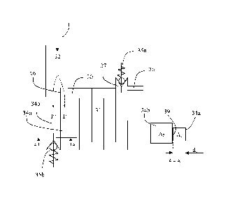
bind to the blood's hemoglobin and then be broken down subsequently.
[0006] NO is formed endogenously along the whole breathing pathway, i.e. in
the oral
cavity, in the sinuses, in the nose, in the trachea past the larynx, in the
bronchia and
within the "free space" in the lungs, as well as in the inner blood-filled
parts of the lungs.
2
As the diagnostic purpose is directed to the condition of the lungs and/or
respiratory tract,
the NO generated in the volume of the mouth, nose, throat and bronchus are of
less
interest and should advantageously be disregarded. The volume of the mouth,
nose,
throat and bronchus is known as the "dead space" and is typically
approximately 2 ml per
kg of body weight, although certain deviations can occur with regard to
physique, age, sex
and the possible use of breathing aids such as tracheotomy or intubation
tubing.
[0007] As the volume of the "dead space" should be disregarded there is
a significant
advantage from a diagnostic perspective with collecting a sample for NO
measurement
from the last part or portion of the exhalation. As the last part should be
collected, the
commencing phase is discarded by allowing a volume exceeding the volume of the
"dead
space" by a suitable factor to flow through the device before collecting a
sample.
Furthermore, it is advantageous to allow the exhalation flow from the patient
to settle to a
continuous flow, such that a steady level of exhaled NO is reached. The state
which is
sought after is known as a "plateau" of the exhalation.
[0008] The following paragraph comes from the American Thoracic Society
(ATS) /
European Respiratory Society (ERS) Recommendations for Standardized Procedures
for
the Online and Offline Measurement of Exhaled Lower Respiratory Nitric Oxide
and Nasal
Nitric Oxide, 2005.
[0009] Online methods refer to exhalations where the expirate is
continuously sampled
by the NO analyzer, and the resultant NO profile versus time or exhaled
volume, together
with other exhalation variables (e.g., airway flow rate and/or pressure), is
captured and
displayed in real time. This enables the test administrator to monitor the
exhalation to
ensure conformation to the required flow rate and pressure parameters and the
achievement of an adequate NO plateau. In the exhalation phase two factors are
critical in
ensuring reproducible and standardized measurements of lower respiratory tract
exhaled
NO: (1) exclusion of nasal NO and (2) standardization of exhalation flow rate.
The
exclusion of nasal NO is important in view of the high nasal NO levels
relative to the lower
respiratory tract. This nasal NO can enter the oral expiratory air via the
posterior
nasopharynx. Closure of the velopharyngeal. With biofeedback of expiratory
pressure or
flow rate, most subjects are able to maintain low flow rates that vary little
from the desired
target. In general, an exhalation is deemed adequate if the mean exhalation
flow rate is
0.05 L/second (10%) during the time of the NO plateau generation, and
instantaneous
CA 2857251 2019-04-12
CA 02857251 2014-05-26
WO 2013/095284
PCT/SE2012/051452
3
flow rate is not less than 0.045 L/second or greater than 0.055 L/second at
any time
during the exhalation. If it is not possible to keep within these values, the
results should
still be recorded and the failure to achieve this flow rate criterion noted in
the record. The
duration of exhalation must be sufficient; at least 4 seconds for children
below 12 years
and 6 seconds for children above 12 years and adults. This corresponds to an
exhaled
volume of at least 0.3 L in adults at an exhalation flow rate of 0.05 L/second
to allow the
airway compartment to be washed out and a reasonable plateau achieved. In
general,
patients can exhale comfortably up to 10 seconds, and this may be necessary
for the
achievement of a stable NO plateau. The plateau concentration in NO should be
evaluated over a 3-second (0.15 L) window of the exhalation profile. A plateau
is defined
according to the following guidelines, two points, A and B, which should be
chosen to
define the first 3-second window in the exhaled concentration profile such
that the
absolute magnitude of A¨B is less than 10%. The plateau concentration, FeNO,
is then
defined at the mean concentration over this 3-second window.
[0010] To meet the requirements of the ATS/ERS, a total of 0.15L must be
collected
and analyzed during online NO measurement and a total of at least 0.3L for an
adult
needs to be used to gather the 0.15L to be measured, i.e. 0.15L needs to be
discarded.
[0011] US 6038913 to Persson et al. discloses a device for collecting and
separating
the first exhalation volume from the "dead space" of the patient (and of the
instrument) in
a first chamber, whereafter the sample for measurement is collected in a
different
chamber having a volume of at least the required 0.15L. The device thus takes
a sample
of at least 0.15L from the plateau-region for analysis, as required by the
ATS.
[0012] J. H. Green in "An introduction to human physiology", 3rd edition,
1966, Oxford
University Press, London, Chapter 5 "Respiration", also discloses (especially
in fig. 99),
the possibility to, during the exhalation, first fill an initial balloon with
air from the "dead
space" and a part of the alveolar air with a second balloon closed-off, and
thereafter
close-off the flow to the said initial balloon and collect the remaining
exhaled air of the
exhalation phase, which comprising the alveolar air, in a second balloon. In
this case, the
contents of oxygen and carbon dioxide are determined. In the filling of both
these
balloons, the patient breaths against a considerable resistance or back-
pressure. Further,
the balloon does not provide a distinct end-point determining the exhaled
volume.
CA 02857251 2014-05-26
WO 2013/095284 PCT/SE2012/051452
4
[0013] In the two examples of prior art devices above a chamber of 0.15L is
required
for the sample collection, which creates a lower limit on the size of the
device which must
be considered to be a substantial design limitation.
Summary
[0014] It is an object of the embodiments herein to address at least some
of the
problems and shortcomings outlined above by using an arrangement and method as
defined in the attached claims.
[0015] A device for measuring a component in exhaled breath is provided.
The device
comprises an inlet for receiving exhaled breath, a buffer chamber, a first
fluid conduit in
fluid connection with the inlet and adapted to lead a first portion of the
exhaled breath to
the buffer chamber. The buffer chamber comprises an outlet for discarding a
first part of
exhaled breath received from the first fluid conduit. This first part may
correspond to the
dead space volume of the exhaled breath. The buffer chamber is configured to
buffer a
second part of exhaled breath received from the first fluid conduit. The
second part may
correspond to the "plateau" of the exhalation. The device further comprises a
second fluid
conduit in fluid connection with the inlet and adapted to lead a second
portion of the
exhaled breath to be discarded, and a sensor for measuring a component in the
exhaled
breath buffered in the buffer chamber. By discarding a portion of the exhaled
breath a
smaller sample can be measured which enables the construction of the device to
be
smaller.
[0016] The device and sensor could according to one embodiment be adapted
to
measure the content of NO as a component in the exhaled breath, but in other
conceivable embodiments the sensor is a sensor adapted to determine the
concentration
of other components of the exhaled breath, such as carbon dioxide (002) carbon
monoxide (CO), ammonia (NH3), acetone ((CH3)2C0), methanol (CH3OH) or ethanol
(C2H5OH).
[0017] According to one embodiment of the device, the first fluid conduit
has a first flow
cross-section area, perpendicular to the direction of the flow in the first
fluid conduit, and
the second fluid conduit has a second flow cross-section area, perpendicular
to the
direction of the flow in the second fluid conduit. The second flow cross-
section area is
larger than the first flow cross-section area, which means that the discarded
portion is
CA 02857251 2014-05-26
WO 2013/095284 PCT/SE2012/051452
larger than the portion collected to be measured. The first flow cross-section
area could
be at least one of: 0.5 times the area of the second flow cross-section area,
0.4 times the
area of the second flow cross-section area, 0.3 times the area of the second
flow cross-
section area, 0.2 times the area of the second flow cross-section area, and
0.1 times the
area of the second flow cross-section area.
[0018] According to one embodiment of the device the buffer chamber
comprises a
buffer conduit, wherein the outlet is arranged at a distal portion of the
buffer conduit with
respect to the inlet or the first fluid conduit.
[0019] According to one embodiment of the device, the buffer conduit has a
cross-
sectional dimension, perpendicular to the direction of the flow in the buffer
conduit, having
a length: less than 1/5 of the length of the buffer conduit, less than 1/10 of
the length of
the buffer conduit, less than 1/20 of the length of the buffer conduit, less
than 1/50 of the
length of the buffer conduit, less than 1/70 of the length of the buffer
conduit or less than
1/100 of the length of the buffer conduit. By the buffer chamber being
elongated by means
of an elongated buffer conduit, the sample of exhaled breath collected in the
buffer
chamber is exchanged with minimal dilution.
[0020] According to one embodiment of the device, the buffer conduit
comprises a
maze, a meandering or at least one S-shape with the purpose of prolonging the
flow path
whilst keeping the buffer chamber compact and thus the outer measurements of
the
measurement device. The corners of the fluid conduit with at least one meander
or S-
shape may have rounded inside corners.
[0021] According to one embodiment of the device, the device further
comprises a
bifurcating wall adapted to separate the first fluid conduit from the second
fluid conduit.
The bifurcating wall may be adjustable such that the relationship between the
first and
second cross-section areas can be altered, for changing the amount of fluid
flowing into
the first and second fluid conduits, respectively. According to another
embodiment the
device comprises a replaceable adjustment member, for changing the amount of
fluid
flowing into the first and second fluid conduits, respectively. By enabling
the adjustment of
the bifurcating wall and/or replacement of the adjustment member, the
measurement
device could be adapted for individuals having respiratory tracts of different
volume, and
thus always measure exhaled breath representing the same relevant areas of the
respiratory tract of the patient.
CA 02857251 2014-05-26
WO 2013/095284 PCT/SE2012/051452
6
[0022] According to one embodiment of the device, the buffer chamber
further
comprises a first check valve, preferably placed at the outlet, such that
fluid will be
stopped from entering the buffer chamber during inhalation..
[0023] According to one embodiment of the device, the device further
comprises a
second check valve placed in the second fluid conduit such that fluid will be
stopped from
entering the second fluid conduit during inhalation
[0024] According to one embodiment, the device comprises a sensor for
sensing the
amount of NO in a fluid flow. By using the buffer chamber disclosed herein,
the device can
be made very small.
[0025] According to one embodiment, the device further comprises a pump
adapted to
pump exhaled breath from the buffer chamber to the sensor.
[0026] According to one embodiment, the sensor is a sensor with a long
response time
requiring exposure to the exhaled breath longer time than the duration of an
exhalation.
An example of such a sensor is an electrochemical sensor. The sensor may have
a
response time of more than 5 seconds, or in the range of 5-15 s.
[0027] A method of measuring the concentration of a component in exhaled
breath is
further provided. The method, comprises the steps of;
- receiving exhaled breath,
- leading a first portion of the exhaled breath through a first fluid
conduit to a buffer
chamber,
- leading a second portion of the exhaled breath through a second fluid
conduit to be
discarded,
- from the buffer chamber, discarding a first part of the first portion of the
exhaled breath
received from the first fluid conduit,
- in the buffer chamber, buffering a second part of the first portion of
the exhaled breath
received from the first fluid conduit, and
- measuring the concentration of the component in the exhaled breath buffered
in the
buffer chamber.
[0028] The method is preferably performed in a device as disclosed herein
and the
component may be NO.
CA 02857251 2014-05-26
WO 2013/095284
PCT/SE2012/051452
7
[0029] According to one embodiment the method comprises the step of
adjusting the
flow of fluid into the first and second fluid conduits respectively. By
adjusting the fluid flow,
different time phases of the exhalation can be selected, which for example is
required if a
patient is unable to complete the full preferred three seconds of exhalation,
or if a
particular region of the respiratory tract is of special interest.
[0030] According to one embodiment, the NO measuring device further
comprises an
adjustment member, and the step of adjusting the flow of fluid comprises
adjusting the
adjustment member or replacing the adjustment member. The adjustment member
could
for example be a bifurcating wall, and the step of adjusting the adjustment
member could
comprises adjusting the bifurcating wall.
[0031] Further possible features and advantages of this solution will
become apparent
from the detailed description below.
Brief description of drawings
[0032] Some possible embodiments will now be described, by way of example,
with
reference to the accompanying drawings, in which:
[0033] Fig. 1 is a graph of exhaled breath showing the dead space portion
and the
portion to be analyzed,
[0034] Fig. 2 is a graph of exhaled breath showing which portions of the
exhaled
breath that are to be discarded,
[0035] Fig. 3 schematically shows a device according to one embodiment,
[0036] Fig. 4 schematically shows a device according to another embodiment,
and
[0037] Fig. 5 schematically shows a device according to yet another
embodiment.
Detailed description
[0038] A device comprising a buffer chamber for use in a medical device for
measurement of exhaled breath for diagnostic purposes is provided. The device
CA 02857251 2014-05-26
WO 2013/095284 PCT/SE2012/051452
8
comprises an inlet adapted to receive breath exhaled by the patient. A flow
adjustment
unit may be provided along the flow conduit leading from the inlet to the
buffer chamber
with the purpose of establishing a constant flow into the buffer chamber. The
flow conduit
further comprises a bifurcation separating the flow of exhaled breath into a
first flow to be
analyzed and a second flow to be discarded. By continuously discarding a
portion of the
flow by means of a bifurcation, a gas sample of less volume is collected.
Collecting a gas
sample of smaller volume enables the construction of a smaller and less energy
consuming measurement device.
[0039] Buffered is to be understood as temporarily stored and buffer
chamber is to be
understood as a chamber suitable for temporary storage.
[0040] The portion of exhaled breath which is collected for analysis is led
into an S-
shaped fluid channel of the buffer chamber, creating an elongated portion of
air which can
be flowed over a sensor for measuring components of that particular portion of
air. By
creating an elongated air portion, the content in the buffer chamber is
rapidly exchanged
with as little dilution as possible, i.e. mixing of old exhaled breath or
ambient air with the
exhaled breath to be measured.
[0041] The device comprising the buffer chamber is adapted to be a part of
an online
measurement device for airway inflammatory diagnostics which according to one
embodiment comprises a sensor with a long response time requiring exposure to
the
exhaled breath longer time than the duration of an exhalation, which requires
the exhaled
air to be buffered for creating a flow over the sensor which is extended in
time. An
example of such a sensor is an electrochemical sensor.
[0042] In the following, a detailed description of exemplifying embodiments
of the
buffer chamber will be given with reference to the accompanying drawings. A
description
of a measurement device adapted for measuring the NO content of exhaled breath
using
the buffer chamber will also be given as an example of an application of the
device.
However, it should be understood that the device may be used in combination
with any
type of sensor for the measurement of exhaled breath, such as a device for
measurement
of carbon dioxide (CO2) carbon monoxide (CO), ammonia (NH3), acetone
((CH3)2C0),
methanol (CH3OH) or ethanol (C2H5OH). It will be appreciated that the figures
described
are for illustration only and are not in any way restricting the scope of the
invention.
Please note that any embodiment or part of embodiment as well as any method or
part of
CA 02857251 2014-05-26
WO 2013/095284 PCT/SE2012/051452
9
method could be combined in any way. All examples herein should be seen as
part of the
general description and therefore possible to combine in any way in general
terms. It
should be noted that the units of the measurement device merely illustrate the
nodes or
functional units in a logical sense, although the skilled person is free to
implement these
functions in other locations of the conduit in practice as long as the
function of the
particular unit remains.
[0043] Fig. 1 shows a graph of a flow of exhaled breath over time (t). In
embodiments
where NO is to be measured for performing diagnostics related to the condition
of the
lungs and/or respiratory tract of the patient, the NO generated in the volume
of the mouth,
nose, throat and bronchus are of less interest and should advantageously be
disregarded.
This volume is known as "dead space" and is represented by the shaded part 11
in the
graph. Apart from less interesting regions of the airways, the discarding of
the dead space
further takes care of the volume of ambient air present in the inlet conduit
and the flow
regulator of the measurement device. This volume typically represents 2 ¨ 8
seconds (t=0
¨ t=1) of the exhalation. Furthermore, an advantage with discarding the first
part of the
exhalation and performing analysis of a second subsequent part is that the
exhalation flow
from the patient is allowed to settle to a continuous flow which creates a
more steady level
of exhaled NO, a state which is known as a "plateau" of the exhalation.
[0044] After the dead space portion 11 of the exhaled breath, the second
part
representing the region of interest 12 is illustrated. The second part of
breath to be
measured is collected during the remainder of the exhalation. According to
ATS/ERS
guidelines, a plateau concentration of NO should be evaluated over a 3-second
window of
the exhalation profile. For an adult this means that at least 0.3L needs to be
used to
gather 0.15L to be analyzed, i.e. at least 0.15L needs to be discarded. Part
11 represents
the at least 0.15L to be analyzed which is collected during the time t=1 ¨
t=2.
[0045] Fig. 2 is a graph showing the different volumes of exhaled breath
collected in a
device comprising a buffer chamber according to embodiments disclosed herein.
The first
parts 21, 24, which are the parts of exhaled breath representing t=0 ¨ t=1, is
in
accordance with fig. 1 representing the air from the dead space which is
discarded prior to
the collection of the sample to be measured. The sample portion 22 and 23
collected from
time t=1 until t = 2 is divided by means of the inlet of the buffer chamber
(which is further
disclosed with reference to figs. 3 ¨ 5) into a first part 22 which is to be
discarded and a
CA 02857251 2014-05-26
WO 2013/095284 PCT/SE2012/051452
second part 23, which is to be collected in the buffer chamber and
subsequently analyzed.
By continuously separating a portion 21 and 22 from the flow of exhaled
breath, the
portion 23 and 24 representing the exhaled breath may have a small volume.
Further, by
discarding a first part 24 of the portion representing the exhaled breath and
buffering only
the second part 23 for analysis the part 23 of the first portion to be
analyzed can have a
much smaller volume whilst still representing the entire interesting region of
the patient's
airways. The separated portion 24, 23 for analysis is denoted as X% of the
total of 100%
of the breath gas, and X% could according to one embodiment be 1/3 of the
total volume
of exhaled breath. However, according to other embodiments, the separated
portion 24,
23 for analysis could be as much as 90%, 80% 60% 40% or 20% or as little as
1%, 2%,
4% or 10% of the total of exhaled breath.
[0046] Thus, according to the device disclosed herein a first portion 23
and 24
corresponding to X% of the exhaled breath is conducted to the buffer chamber.
In the
buffer chamber a first part 24 of the first portion of exhaled breath is
discarded and a
second part 23 of the first portion of exhaled breath is buffered for
analysis. The second
portion 21 and 22 of the exhaled breath is discarded.
[0047] Fig. 3 shows the device having a buffer chamber 31 according to an
embodiment in which the device comprises an inlet 32 adapted to receive an
inflow I of
breath exhaled by a patient. The inlet comprises a fluid conduit which
transports the
exhaled breath I towards a bifurcation 39 adapted to separate a first portion
l' of the
exhaled breath to be analyzed, from a second portion l" of the exhaled breath
I, which is
to be discarded. The bifurcation 39 divides the fluid conduit 39 into a first
fluid conduit 34a
and a second fluid conduit 34b. The second fluid conduit 34b guides the second
portion l"
of the exhaled breath to be discarded. According to the embodiment disclosed
in fig. 3,
the second portion l" of the exhaled breath is a larger portion of the total
of the exhaled
breath I, for example 2/3. The second portion l" guided by the second fluid
conduit 34b is
discarded through a check valve 35b and further to the ambient air. The first
portion l' of
the exhaled air is separated by the bifurcation 39 and guided by the first
fluid conduit 34a
into the conduits making up the buffer chamber 31. The conduits making up the
buffer
chamber 31 creates an S-shaped lumen 30 in which the collected breath is
buffered. From
the buffer chamber a first part of the first portion of exhaled breath is
discarded through
the outlet 37 and a second part of the first portion of exhaled breath is
buffered in the 5-
shaped lumen for analysis. The S-shaped lumen 30 creates an elongated portion
of air
CA 02857251 2014-05-26
WO 2013/095284 PCT/SE2012/051452
11
which can be flowed over a sensor for measuring the NO content of that
particular portion
of air. By creating an elongated air portion, the content in the buffer
chamber 31 is rapidly
exchanged with as little dilution as possible, i.e. mixing of old exhaled
breath or ambient
air with the exhaled breath to be measured.
[0048] At the end of the S-shaped lumen 30, a fluid conduit 36 for leading
the collected
sample from the buffer chamber 31 to the sensor is placed. The collected
breath is
according to this embodiment pumped over the sensor by means of a pump, such
as a
membrane pump (further described under reference to fig. 5). The other outlet
37 from the
S-shaped lumen 30 of the buffer chamber 31 is the outlet 37 for discarding the
first part of
the exhaled breath corresponding to the dead space portion of the first
portion l' through a
check valve 35a and further to the ambient air. The purpose of the two check
valves 35a,
35b is that no ambient air should leak into the fluid conduits / buffer
chamber 31 of the
device and dilute and/or contaminate the sample. Furthermore, the check valves
35a, 35b
enable the inhalation of air through an NO-scrubber (which is further
disclosed under
reference to fig. 5), which guarantees that exhaled NO originates from the
airways of the
patient and not from the ambient air. The ambient air could for example be
contaminated
by exhaust fumes from for example heavy vehicles, or residue anesthesia gases,
which
may be present in a hospital environment.
[0049] The section A ¨ A shows the first fluid conduit 34a having a first
flow cross-
section area A1, perpendicular to the direction of the flow in the first fluid
conduit 34a, and
the second fluid conduit 34b having a second flow cross-section area A2,
perpendicular to
the direction of the flow in the second fluid conduit 34b being larger than
the first flow
cross-section area Al. According to some embodiments, the first flow cross-
section area
A1 is 0.5, 0.3, 0.2 or 0.1 times the area of the second flow cross-section
area A2. The
section A ¨ A further shows the first fluid conduit 34a having a cross-section
distance dl
being perpendicular to the direction of the flow in the first fluid conduit
34a having a length
less than 1/5, 1/10, 1/20, 1/50 or 1/100 of the length of the first fluid
conduit 34a. The first
fluid conduit is making up the buffer chamber 31 such that an elongated S-
shaped lumen
30 is created for enabling the exchange of the air present in the buffer
chamber with
minimum dilution.
[0050] The first portion of fluid flow l' described in fig. 3 represents
the relevant fluid
flow for measurement denoted as X% of the total flow in fig. 2. Thus the first
and second
CA 02857251 2014-05-26
WO 2013/095284 PCT/SE2012/051452
12
parts 24 and 23 from fig. 2 represents the first portion of fluid flow l' of
which the part 24 is
the dead space sample which is discarded through the first check valve 35a.
The second
portion of fluid flow l" is in fig. 2 represented by the parts 21 and 22
making up the portion
from X% to 100% of the total exhaled breath. The second portion of fluid flow
l" is to
continuously be discarded through the second check valve 35b.
[0051] Thus, during operation of the device, exhaled breath is received at
the inlet 32.
A first portion l' of the exhaled breath is led through the first fluid
conduit 34a to the buffer
chamber 31. A second portion (I") of the exhaled breath is led through a
second fluid
conduit 34b to be discarded. From the buffer chamber, a first part of the
first portion l' of
the exhaled breath received from the first fluid conduit is discarded through
the outlet 37,
and a second part of the first portion l' of the exhaled breath received from
the first fluid
conduit is buffered in the buffer chamber for analysis.
[0052] Fig. 4 shows an embodiment of the buffer chamber which is very
similar to the
embodiment described under reference to fig. 3, with the difference that the S-
shaped
lumen 30 has rounded inside corners 38 which further improves the exchange of
sample
breath in the buffer chamber 31 as it reduces the risk that old sample breath
and/or
ambient air is trapped in the corners of the S-shaped lumen 30 of the buffer
chamber 31
making the measurement more accurate. Fig. 4 furthermore shows the bifurcating
wall
39', adapted to separate the first fluid conduit 34a from the second fluid
conduit 34b, being
adjustable such that the relationship between the first 34a and second 34b
cross-section
areas can be altered, for changing the amount of fluid flowing into the first
34a and second
34b fluid conduits, respectively. By enabling the adjustment of the
bifurcating wall 39',
different time phases of the exhalation can be selected, which for example is
required if a
patient is unable to complete the full preferred three seconds of exhalation,
or if a
particular region of the respiratory tract is of special interest.
[0053] Fig. 5 shows a system overview comprising the device disclosed under
reference to fig. 4. The system overview comprises an inlet 64 into which the
patient is to
exhale and inhale. The first step of a measurement process is that the patient
inhales
through the inlet 64 so that the quality of the inhaled ambient air can be
controlled. The
inhaled air is according to the embodiment shown in fig. 5 purified by means
of a scrubber
66 removing NO from the ambient air to establish that the entire concentration
of NO
comes from the patient's airways. The scrubber 66 could for example comprise
potassium
CA 02857251 2014-05-26
WO 2013/095284 PCT/SE2012/051452
13
permanganate (KMn04) or potassium permanganate in combination with a suitable
grade
of carbon in granular form. The check valve 67 guarantees that air passes
exclusively
through the scrubber 66 during the inhalation phase, so that the all of the
exhaled breath
is led into the measurement device. The inflow of exhaled breath I is passed
though a flow
adjustment unit 65 adapted to normalize the flow of exhaled breath, such that
a
continuous flow representing the interesting regions of the patient's airways
is achieved.
After the flow adjustment unit 65 the flow of exhaled breath I is guided in
accordance with
the description made under reference to figs. 3 and 4.
[0054] The buffered exhaled breath is pumped from the buffer chamber 31 by
means
of a pump 61 placed along a fluid conduit 36 leading from the buffer chamber
31 to the
sensor 63. The pump could for example be a membrane pump which makes sure that
there is no back-flow through the pump contaminating the sample breath in the
buffer
chamber during the inhalation and/or exhalation phase. The sensor 63 is
according to this
embodiment an electrochemical sensor with a relatively slow response, leading
to the
need for the buffer chamber 31 and the pump 61. The pump flows the collected
sample
breath over the sensor at such a rate that the sensor 63 has sufficient time
to respond to
the NO content of the breath and thus being able to accurately sense
inflammation in the
airways indicated by the NO content.
[0055] Fig. 5 further shows an alternative embodiment of the bifurcating
wall, in which
the bifurcating wall comprises an adjustment member 70 comprising apertures
71, 72, the
size of which determines the flow into the first 34a and second 34b fluid
channels,
respectively. The first aperture 72, adapted to lead a fluid flow into the
first flow channel
34a, could have a cross-section area being 0.8, 0.5, 0.3, 0.2 or 0.1 times as
large as the
cross-section area of the second aperture 71. The adjustment member 70 could
be
replaceable to an adjustment member 70 having a different relationship between
the sizes
of the first and second apertures 72, 71. By enabling the adjustment of the
sizes of the
apertures 71, 72, different time phases of the exhalation can be selected,
which for
example is required if a patient is unable to complete the full preferred
three seconds of
exhalation, or if a particular region of the respiratory tract is of special
interest.
[0056] Please note that any embodiment or part of embodiment as well as any
method
or part of method could be combined in any way. All examples herein should be
seen as
part of the general description and therefore possible to combine in any way
in general
CA 02857251 2014-05-26
WO 2013/095284
PCT/SE2012/051452
14
terms. It should be noted that the units of the measurement device merely
illustrate the
nodes or functional units in a logical sense, although the skilled person is
free to
implement these functions in other locations of the conduit in practice as
long as the
function of the particular unit remains.