Note: Descriptions are shown in the official language in which they were submitted.
CA 02857669 2014-05-30
WO 2013/082334 PCT/US2012/067149
GATEWAY DEVICE, SYSTEM AND METHOD
Cross-Reference to Related Application
This application claims the benefit of US Provisional Application No.
61/565,473, filed
November 30, 2011 and US Non-Provisional Application No. 13/689,749, filed
November 29,
2012.
Technical Field
This application relates to networked system and in particular gateway
devices, systems
and methods.
Background Art
It is becoming increasingly common for homes, businesses, etc. to have access
to a wide
variety of networked or remote services. Illustrative services include
Internet service, cellular
voice and data services, on-line services, phone services (PSTN, POTS. VoIP,
etc.), cable
television services, satellite television services, satellite radio services,
etc. Unfortunately, it is
quite common for at least some of these services to each have their own access
point as well as
required hardware. As such, homes and businesses are frequently cluttered with
numerous wires
and cables as well as "electronically cluttered" with a variety of wireless
access or
communication points. Therefore, there exists a significant need for the
ability to combine the
access points to a significantly smaller number of access points as well as
manage the
communications between devices and networks.
CA 02857669 2014-05-30
WO 2013/082334 PCT/US2012/067149
Disclosure of Invention
The present disclosure includes several embodiments of gateway devices,
network
systems and methods. In one embodiment, a local network system comprises; one
or more
termina:k operable to act as a client on the local network, wherein at least
one terminal is a
remote control configured. to receive user input; a gateway device operable to
manage
communications between the one or more terminals and an external network, the
gateway device
comprising: a memory configured to store a set of instructions; a processor
configured to execute
the set of instructions a first communications module in communication with
the external
network; a second communications module for providing communication between
the gateway
device and at least one terminal; and a third communications module for
providing
communication between the gateway device and at least one other terminal.
In another embodiment, A method of employing a remote control in a local
network
system, the local network system comprising a gateway device and one or more
terminals,
wherein at least one terminal is a remote control, the method comprises:
receiving a user
configuration for the remote control; storing the user configuration for the
remote control;
receiving a user log-on for the remote control.; and loading the stored user
configuration for the
remote control.
In another embodiment, a remote control ibr use in a local network system, the
system
comprising a gateway device in communication with one or more terminals and
the remote
control, the remote control comprises: memory configured to store a set of
instructions; a
processor configured to execute the set of instructions, wherein the
instructions cause the
processor to: receive a user configuration for the remote control; and store
the user
configuration for the remote control.
2
CA 02857669 2014-05-30
WO 2013/082334 PCT/US2012/067149
Brief Description of the Drawings
The drawings, when considered in connection with the following description,
are
presented for the purpose of facilitating an understanding of the subject
matter sought to be
protected.
FIG. 1 is a first illustrative system.
FIG. 2 is a second illustrative system.
FIG. 3 is a third illustrative system.
FIG. 4 is a fourth illustrative system.
FIG 5 is a fifth illustrative system.
FIG. 6 is a sixth illustrative system.
FIG. 7 is an illustrative gateway device.
FIG 8 is an illustrative method for transferring calls between a gateway
device and a
telecommunications network.
FIG 9 is an illustrative method for communicating caller ID information.
FIG 10 is an illustrative method for providing on-demand services.
FIG. 11 is an illustrative method for providing dynamic control of streamed
content.
FIG. 12 is an illustrative method for providing parental controls.
FIG. 13 is an illustrative method for providing text messages.
FIG 14 is an illustrative system employing a remote control.
FIG. 15 is an illustrative method of employing a remote control.
FIG. 16 is an illustrative block diagram of a remote control.
Modes for Caffying Out the Invention
Referring now to the FIGS. wherein like elements are referred to with the same
numerals
3
CA 02857669 2014-05-30
WO 2013/082334 PCT/US2012/067149
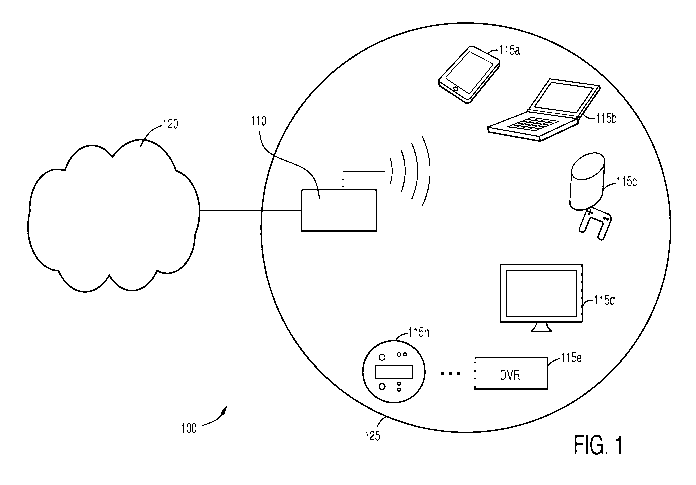
throughout and wherein FIG. 1 illustrates a system 100 in accordance with the
present disclosure.
The system 100 includes a gateway device 110, one or more terminals 11 5a- 11
5n (collectively
115), and an external network 120.
The external network 120 may include any number of networks capable of
providing
communications to and/or receiving communications from the gateway device 110.
For
example, the external network may be one or more, or any combination of,
wireless networks,
data or packet networks, publicly switched telephone networks (PSTN), cellular
networks, wide
area networks (WAN), adjacent local area networks (LAN), etc. In one
embodiment, the external
network 120 includes the Internet.
The participant terminals 115 may include any suitable device operable to act
as a client
on a network. Illustrative terminals 115 include, but are not limited to,
personal computers,
desktop computers, laptop computers, tablet computers, video game systems,
servers, any
suitable telecommunications device, including, but not limited to, VoIP
telephones, smart
telephones or wireless devices, such as cellular telephones, personal digital
assistants (PDA),
communications enabled mp3 players, etc., smart meters, closed circuit
television systems,
communications enabled televisions, DVRs, set top boxes, satellite radio
receivers, printers,
copiers, switches, enterprise switches, network access storage (NAS), or any
other device
suitable to act as a terminal on the local network. The terminals 115 may
communicate with the
gateway 110 using wireless communications or hardwired connections, such as
fiber optics,
cable. DSL, telephone lines, and other similar connections.
As will be further discussed below, the gateway device 110 and terminals 115
form a
local area network (LAN) 125 such that the gateway device 110 manages
communications
between the external network 120 and LAN 125. Further, the gateway device 110
is configured
4
CA 02857669 2014-05-30
WO 2013/082334 PCT/US2012/067149
to provide communications between and otherwise manage or control
communications between
the terminals 115 and the external network 120.
The gateway device 110 includes a plurality of communications modules to
communicate
with one or more of the external network 120 and terminal(s) 115. In one
embodiment, the
gateway device 110 includes a first communication module configured to
communicate with the
external network 120. Illustrative first communications modules, include
without limitation, a
WAN communications module (e.g. any DocSIS, DSL, xDSL, ADSL, ADSL 2, ADSL 2+,
VDSL, VDSL2, SHDSL, GbE, ONT, (WON ONT, SPON ONT, EPON ONT, BPON ONT,
MoCA, TDM, any T-carrier, any E-carrier, any J-carrier, etc.), a WLAN
communications
module, an Ethernet communications module, or any other suitable
communications module.
Additionally, it will be appreciated that the term "module" should be
understood broadly so as to
encompass any device for communicating with an external network including, but
not limited to
one or any combination of moderns, peripheral cards, modules, on-chip
arrangements,
transmitters, receivers, transreceivers, etc.
The gateway device 110 further includes one or more communications modules for
communicating with one or more terminals 115. The second, third, fourth, etc.
communications
module(s) for communicating with one or more terminals 115 may include,
without limitation, a
voice gateway communications module, an Ethernet communications module, a VoIP
communications module, a Femto communications module, a Zigbee communications
module, a
WiFi communications module, WHDMI communications module, print servers, DVR
communications module, etc. In one embodiment, one or more of the
communications modules
is a wireless USB-based communications module (e.g. a wireless WHDMI USB
module, etc.). It
will be appreciated that any communications module, or any number or
combination of
CA 02857669 2014-05-30
WO 2013/082334 PCT1US2012/067149
communications modules, configured to communicate with one or more terminals
may be
employed and remain within the scope of the present disclosure.
Suitable illustrative communications modules for communicating with the
external
network 120 and/or terminals 115 of the system include, without limitation:
the PacketAMC
board offered by ADAX, Inc.; any of the AMC modules (AM4500, AM4510, AM4520,
etc.)
offered by Kontron AG; the iSPAN 3639 Ti/El controller offered by lnterphase
Corp.; the
ETRX3 Zigbee module offered by Telegesis Ltd.; the XB24-Z7PIT-004 module
offered by Digi
International, Inc.; the Femtocell SoC solution offered by Freescale
Semiconductor Inc.; and the
Starcore Voice Gateway offered by Freescale Semiconductor Inc. However, it
will be
appreciated that any suitable device for providing communication between the
gateway device
110 and the external network 120 and/or terminals 115 may be employed as any
suitable
communication module in the system.
FIGS. 2-6 illustrate several non-limiting examples of the implementation of
the system of
the present disclosure. It will be appreciated that the following illustrative
embodiments are not
intended to limit the scope of the disclosure in any way. Each of the
illustrative embodiments in
FIGS. 2-6 illustrate a variety of terminals in several different settings. It
will be appreciated that
embodiments having a plurality of the same terminal type are expressly
contemplated.
Additionally, it will be appreciated that additional terminal types not shown
may be employed,
including but not limited to the various terminals mentioned above. Also,
fewer terminals than
shown may be employed and that the expression of one terminal type is not at
the exclusion of
all other terminal types. Also, it will be appreciated that the functionality
of the gateway device
110 in one embodiment may be employed in every other embodiment and it will be
appreciated
that expression of only a certain functionality in one embodiment is not at
the exclusion of all
6
CA 02857669 2014-05-30
WO 2013/082334 PCT/US2012/067149
other the functionality described in other embodiments herein.
FIG. 2 illustrates the implementation of the gateway device 110 as a home
communication and entertainment gateway. In this embodiment, the terminals
(collectively 315)
include a television 315a, a mobile device 315b, a computer 315c, a smart
meter 315d, a security
system 315e, a gaming system 315f and a DVR/STB 315g. The gateway device 110
manages
communications between the terminals 315 and external network 120. For
example, the gateway
device 110 may permit access to the external network 120 by one or more of the
terminals 315 ¨
this may include, without limitation, providing communications between one or
more of the
terminals and the external network 120 by transferring data between the
terminals 315 and
network 120, which may include converting the data so that it is usable by the
terminals 315 or
endpoint in the external network 120, etc. For example, and without
limitation, the gateway
device 110 may act so as to permit one of the terminals to access the
Internet, etc. Additionally,
the gateway device 110 may manage communications between the terminals 315.
For example,
and without limitation, the gateway device 110 may receive a command from one
terminal and
pass the command to a second terminal such that the second terminal is
responsive to the
command from the first terminal (e.g. a record command from the mobile device
315b or
computer 315c to the DVR/STB 315g, etc.). Furthermore, the gateway device 110
may manage
remote access to one of the terminals 315 over the external network 120. For
example, and
without limitation, a remote device 317 (e.g. mobile device, computer, etc.)
may be permitted to
access one of the terminals 315 so as to allow control of the terminal (e.g.
remote access to
control a smart meter 315d, security system 315e, DVR/STB 315g, etc.).
FIG. 3 illustrates the implementation of the gateway device 110 in an office
setting. The
gateway device 110 may be configured to serve as a small home office gateway,
a multi-service
7
CA 02857669 2014-05-30
WO 2013/082334 PCT/US2012/067149
business gateway or any other suitable gateway or device. In this embodiment,
the terminals
(collectively 415) include a switch 415a, such as an enterprise switch, which
is connected to
devices such as a multifunction device (copier/scanner/printer) 415b,
workstations 415c, phones
such as ISDN lines 415d or VoIP lines 415e. It will be appreciated that in
some instances a
switch may not be desirable or necessary and that a switch 415a may not be
employed and the
terminals placed in direct communication with the gateway device 110. Further,
even in
instances where a switch 415a is employed, it may still be desirable for
certain terminals to be in
direct communication with the gateway 110 including, but not limited to,
workstations 415f,
network access storage (NAS) 415g, printers/scanners 415h, VolP phone. any
Power Over
Ethernet (POE) enabled device, etc. The gateway device 110 may manage
communications
between the external network 120 and the terminals 415 as well as
communications between
terminals 415.
Referring now to FIG. 4, a gateway device 110 is shown in communication with
smart
meters (collectively 515). As used herein, the term smart meter refers to any
device configured
to monitor and/or control utilities, utility services, or the like.
Illustrative smart meters include,
without limitation, smart breaker boxes 515a, lighting control systems 515b,
smart electric
meters 515c, smart gas meters, smart water meters, industrial PLCs, access
control systems,
smart appliances, or any other suitable device or devices. In one embodiment,
the gateway
device 110 manages communications between one or more smart meters 515 such
that the
meter(s) 515 may be monitored or controlled by another terminal (not show in
FIG. 5). Also, in
one embodiment, the gateway device 110 may be configured to allow remote
access to one or
more smart meters 515 over the external network 120 such that a remote device
517 (e.g. mobile
device. computer, etc.) may be permitted to access, monitor and/or control the
smart meter(s)
8
CA 02857669 2014-05-30
WO 2013/082334 PCT/US2012/067149
515. It will be appreciated that the gateway device 110 provide smart meter
management,
including but not limited to energy grid management, for home area networks
(HAN) as well as
field area networks (FAN).
Referring now to FIG 5, another embodiment employing the gateway device 110 is
shown. In this embodiment, the terminals 615a-615n, collectively 615, include
components for a
closed-circuit television arrangement. In one embodiment, each of the
terminals 615 is a camera
such as a video camera, infrared camera, FLIR camera, thermographic camera, or
any other
device or devices suitable for a closed-circuit arrangement. In one
embodiment, a terminal is a
network digital video recorder 618 to which at least some of the cameras 615
are in
communication with. Alternatively, if the gateway device includes persistent
storage, the footage
from the terminals may be stored thereon. In one embodiment, the gateway
device ll 0 manages
communications between other terminals (not shown) and the camera terminals
615 so that the
other terminals are able to view, monitor and/or control the camera terminals
615 as well as view
recorded footage from the cameras that is stored in the network digital video
recorder 618 and/or
persistent storage of the gateway device 110. Also, in one embodiment, the
gateway device 110
may be configured to allow remote access to one or more of the terminals 615
and/or 618 over
the external network 120 such that a remote device (e.g. mobile device 617a,
computer 617b,
etc.) may be permitted to view, monitor and/or control the camera terminals
615 as well as view
recorded footage from the cameras that is stored in the network digital video
recorder 618 and/or
persistent storage of the gateway device 110. Further, in one embodiment, the
gateway device
may be configured to enhance the stored video footage so as to enhance the
quality of the video
or any other suitable aspect or characteristic of the video.
Referring now to FIG. 6, the gateway device 110 may be configured to also act
as a
9
CA 02857669 2014-05-30
WO 2013/082334 PCT/US2012/067149
unified communication controller. Here, the terminals (collectively 715) may
include a video
camera 715a, a microphone 715b, and a monitor or television 715c. The
terminals may be
discrete devices or combined in any suitable combination for an integrated
device. The gateway
device 110 may be configured to provide communications between each of the
terminals 715 and
the external network 120 such that the gateway device 110 is operable to
provide real time video
conferencing.
Referring to FIG 7, a block diagram of a gateway device 110 is shown in which
the
illustrative embodiments may be implemented. Computer-usable program code or
instructions
implementing the processes used in the illustrative embodiments described
herein, including all
methods. may be located on the gateway device 110. The gateway device 110
includes a
communications fabric 210, which provides communications between a processor
unit 215, a
memory 220, a persistent storage 225 the first communications module 230,
second
communications module 235 and third communications module 240. While three
communications modules are shown herein, it will be appreciated that any
number of
communications modules may be employed and remain within the scope of the
present
disclosure. Further, it will be appreciated that in some embodiments the
gateway device 110 may
not include a persistent storage 225.
The processor unit 215 serves to execute instructions for software that may be
loaded into
the memory 220. The processor unit 215 may be a set of one or more processors
or may be a
multi-processor core, depending on the particular implementation. Further, the
processor unit
215 may be implemented using one or more heterogeneous processor systems in
which a main
processor is present with secondary processors on a single chip. As another
illustrative example,
the processor unit 215 may be a symmetric/asymmetric multi-processor system
containing
CA 02857669 2014-05-30
WO 2013/082334 PCT/US2012/067149
multiple processors of the same type.
The memory 220, in these examples, may be, for example, a random access memory
or
any other suitable volatile or non-volatile storage device. The persistent
storage 225 may take
various forms depending on the particular implementation. For example, the
persistent storage
225 may contain one or more components or devices. For example, the persistent
storage 225
may be a hard drive, a flash memory, a rewritable optical disk, a rewritable
magnetic tape, or
some combination of the above. The media used by the persistent storage 225
also may be
removable. For example, a removable hard drive may be used for the persistent
storage 225. In
one embodiment, the persistent storage 225 also stores video data selectively
stored by a user
(e.g. as a DVR drive, etc.).
The communications modules 230, 235, 240 will be the communications modules as
previously discussed ¨ that is, at least one communications modules is
configured to
communicate with an external network and at least one module is configured to
communicate
with one or more terminals. Each module may take any of the forms previously
discussed. In
one embodiment, one or more of the communications modules includes an ingress
connector
250a-250c (collectively 250) and an egress connector 255a-255c (collectively
255). The ingress
connector 250 may be configured to test the incoming signal to the
communications module
without interruption. The egress connector 255 may be configured to test the
outgoing signal
from the communications module without interruption. Alternatively, an ingress
connector and
an egress connector may each be connected to the board of the gateway device
110 wherein the
memory of the gateway device includes instructions that will allow the
incoming and outgoing
signals for each communications module to be tested via such connection to the
gateway board.
Thus, the line connections for each module may be tested.
11
CA 02857669 2014-05-30
WO 2013/082334 PCT/US2012/067149
Instructions for the operating system and applications or programs are located
on the
persistent storage 225. These instructions may be loaded into the memory 220
for execution by
the processor unit 215. The processes or methods of the different embodiments
may be
performed by the processor unit 215 using computer-implemented instructions,
which may be
located in a memory, such as the memory 220. These instructions are referred
to as program
code, computer-usable program code, or computer-readable program code that may
be read and
executed by a processor in the processor unit 215. The program code in the
different
embodiments may be embodied on different physical or tangible computer-
readable media, such
as the memory 220 or the persistent storage 225.
In one embodiment, program code 260 is located in a functional form on a
computer-
readable media 265 and may be loaded onto or transferred to the gateway device
110 for
execution by the processor unit 215. The program code 260 and the computer-
readable media
265 form computer program product 270 in these examples.
In one example, the computer-readable media 265 may be in a tangible form,
such as, for
example, an optical or magnetic disc that is inserted or placed into a drive
or other device that is
part of the persistent storage 225 for transfer onto a storage device, such as
a hard drive that is
part of the persistent storage 225. In a tangible form, the computer-readable
media 265 also may
take the form of a persistent storage, such as a hard drive or a flash memory
that is connected to
the gateway device 110. The tangible form of the computer-readable media 265
is also referred
to as computer recordable storage media.
Alternatively, the program code 260 may be transferred to the gateway device
110 from
the computer-readable media 265 through a communication link to a
communications module.
The communication link or the connection may be physical or wireless in the
illustrative
12
CA 02857669 2014-05-30
WO 2013/082334 PCT/US2012/067149
examples. The computer-readable media 265 also may take the form of non-
tangible media,
such as communication links or wireless transmissions containing the program
code 260. In one
embodiment, the program code 260 is delivered to the gateway device 110 over
the Internet.
The different components illustrated for the gateway device 110 are not meant
to provide
architectural limitations to the manner in which different embodiments may be
implemented.
The different illustrative embodiments may be implemented in a data processing
system
including components in addition to or in place of those illustrated for
gateway device 110.
Other components shown in FIG 7 can be varied from the illustrative examples
shown.
As one example, a storage device in the gateway device 110 is any hardware
apparatus
that may store data. The memory 220, the persistent storage 225, and the
computer-readable
media 265 are examples of storage devices in a tangible form.
In another example, a bus system may be used to implement the communications
fabric
210 and may be comprised of one or more buses, such as a system bus or an
input/output bus.
Of course, the bus system may be implemented using any suitable type of
architecture that
provides for a transfer of data between different components or devices
attached to the bus
system. Further, a memory may be, for example, the memory 220 or a cache such
as found in an
interface and memory controller hub that may be present in the communications
fabric 210. It
will be appreciated that the communications fabric 210 may take any suitable
form including, but
not limited to, non-blocking switch fabric, non-blocking point-to-point/multi-
point link or any
other suitable communication fabric of communications path(s) between the
various elements.
Referring now to FIGS. 8-13. illustrative methods of the gateway device 110
managing
communications between the external network 120 and/or between the terminals
are shown. It
will be appreciated that the terms "managing" and "controlling" are to be
understood broadly and
13
CA 02857669 2014-05-30
WO 2013/082334 PCT/US2012/067149
encompass not only pushing communications through from the terminal(s) to one
or both of
another terminal and external network, and vice versa, but also converting
data, providing
security checks, storing data, caching data and any other means or method for
optimizing said
communications. Furthermore, while the following methods are discussed
individually, it will be
appreciated that a gateway device 110 may perform any of these methods,
whether
simultaneously, sequentially, selectively, user-selectively, etc., and remain
within the scope of
the present disclosure. Furthermore, the methods may also be employed by any
device other
than a gateway device as described herein and be considered within the scope
of the present
disclosure. Also, while the methods may sometimes refer to a single terminal,
it will be
appreciated that more than one terminal may be employed and remain within the
scope of the
present disclosure.
Referring now to FIG. 8, a method 800 for transferring calls between a
telecommunications network and a gateway device is shown. As used herein,
telecommunications network shall be understood broadly so as to encompass any
network
suitable for providing telecommunications, including but not limited to PSTN,
POTS, cellular
networks, wireless networks, data or packet networks, or any other suitable
network. Further, it
will be appreciated that the gateway device is in communications with an
external network as
described above, telecommunications or otherwise, such that a call may be
transferred to or
otherwise managed, handled or controlled by the gateway device. Also, the
terms "strong,"
-relatively strong," "weak," and -relatively weak" should be understood
broadly so as to
encompass a signal or output compared against a predetermined threshold value
or a
determination of the quality or strength of a signal based on the ability to
maintain service within
a predetermined quality range, or by any other suitable means or metric for
ranking or otherwise
14
CA 02857669 2014-05-30
WO 2013/082334 PCT/US2012/067149
determining the strength and/or quality of a signal.
First, a mobile device (also referred to as a terminal), e.g. cellular phones,
etc., is
registered with the gateway device [step 802]. This will permit the gateway
device to only
recognize or otherwise provide service to the mobile device registered
therewith. Optionally,
this step may include installing an application on the mobile device such that
the mobile device
provides the necessary information to the gateway device (e.g. tower strength,
signal strength of
telecommunications network, etc.) and/or is responsive to commands from the
gateway device
(e.g. handover command, etc.), but it will be appreciated that such an
application may not always
be desirable or necessary.
Once the mobile device(s) have been registered, the gateway device is
configured to scan
or otherwise recognize mobile devices that become within range of the gateway
device [step
804]. In one embodiment, a WiFi and/or a Femto module of the gateway device is
employed for
scanning or otherwise recognizing mobile devices within range. However, it
will be appreciated
that any suitable module or device may be used for this purpose. If it is
determined that a mobile
device is not connected, the gateway will remain in a stand-by mode with
respect to this method
and/or continue to scan for mobile devices [step 806]. Once a mobile device is
detected, the
gateway device will determine if the mobile device is recognized as a device
having been
previously registered with the gateway device [step 808]. In an alternative
embodiment where
the mobile device is configured to provide an initial communication to a
recognized gateway.
this step may be optional or not included in the method. If the mobile device
is not recognized,
the gateway device continues to scan for a recognized mobile device or,
alternatively, awaits an
initial communication from a previously registered mobile device [step 806]
If the mobile device is recognized by the gateway as a registered mobile
device, the
CA 02857669 2014-05-30
WO 2013/082334 PCT/US2012/067149
gateway device will determine the strength of the signal or communications
between the mobile
device and the gateway device [step 8121. If the signal is relatively weak,
the gateway device
may be configured to return to any of the previous steps (e.g. steps 804-810).
If the signal is
relatively strong, the gateway device will query the mobile device to
determine the strength of
the signal between the mobile device and the telecommunications network [step
812]. in one
embodiment, the mobile device is queried for the relative signal strength
between the mobile
device and a cellular tower the mobile device is connected to. However, it
will be appreciated
that the mobile device may be queried about the signal strength between the
mobile device and
any telecommunications network and remain within the scope of the present
disclosure. If the
signal strength associated the telecommunications network is stronger than the
signal strength
between the mobile device and the gateway device, the gateway device may be
configured to
return to any of the previous step (e.g. steps 804-812).
If the signal strength between the mobile device and the gateway device is
stronger, the
gateway device will, if necessary, make the necessary connection via the
external network such
that the call maybe transferred from the telecommunications network to the
gateway device
without interruption. The gateway device may then command the mobile device to
transfer the
call to the gateway device [step 8141.
The gateway device may further be configured to handover a call from a mobile
device in
communication with the gateway device to a telecommunications network. If a
mobile device is
connected to the gateway device [step 804], the gateway device will monitor
the signal strength
and determine if the signal strength is relatively strong or relatively weak
[step 816]. If the
signal is relatively strong, the gateway device will maintain the connection
and continuously or
periodically monitor the signal strength. If the signal strength is relatively
weak, the gateway
16
CA 02857669 2014-05-30
WO 2013/082334 PCT/US2012/067149
device will determine if a telecommunications network is within range [step
818]. This may be
accomplished by the gateway itself or by querying the mobile device to
determine if the mobile
device detects a telecommunications network. If no telecommunications network
is detected, the
gateway may be configured to return to any of the previous steps (e.g. steps
804-815).
If a telecommunications network is detected, the gateway device may determine
whether
the signal or connection with the gateway device is stronger than the signal
to the
telecommunications network [step 820]. If the signal to the gateway device is
stronger, the
gateway device may maintain the connection and may be further configured to
return to one of
the forgoing steps (e.g. steps 804-820). If the signal to the
telecommunications network is
stronger, the gateway device may command the mobile device to initiate a
handover sequence, as
is known in the art, so that the call may be transferred from the gateway
device to the
telecommunications network [step 822]. The method may then be concluded and/or
return to
step 804.
The forgoing method may be employed in a variety of contexts. In one
embodiment, the
mobile device is a cellular phone and the telecommunications network is a
cellular network
whereby the gateway device may transfer a call to Or from the
telecommunications network to an
external network in communication with the gateway device (e.g. PSTN, POTS,
VoIP, etc.). In
another embodiment, rather than a call being transferred, the connection for
streaming data (e.g.
YouTube. Hulu. Netflix, etc.) may be transferred (e.g. between a 3G or 4G
telecommunications
network and an internet connection managed or maintained by the gateway
device, etc.).
Referring now to FIG 9, a method 900 for providing caller ID information to
one or more
terminals is shown. First, one or more terminals are designated to receive
caller ID information
when an incoming call is received by the gateway device from an external
network [step 902].
17
CA 02857669 2014-05-30
WO 2013/082334 PCT/US2012/067149
Next, a call is received wherein the call has caller ID information associated
therewith [step
904]. In response thereto, the gateway device communicates the caller ID
information to the
previously designated devices [step 906].
Referring now to FIG 10, a method 100 for providing on-demand services to one
or more
terminals is shown. On-demand services shall be understood to include any
service for
providing content via an external network to a user or users. Illustrative
content includes video,
audio, or any other suitable content. Illustrative on-demand service providers
include, without
limitation, Hulu , YouTube , Netflix , Pandora , Songza and the like. First,
the registration
information for each on-demand service is entered and stored in the gateway
device [step 1002].
A search request from at least one terminal may then be received [step 1004].
The search request
may then be communicated to each on-demand service via the external network
[step 1006]. The
search results from each on-demand service may then be received [step 1008].
The search
results may then be communicated to one or more terminal(s) [step 1010]. A
command, such as
play, download, etc., from a terminal may then be received [step 1012]. The
gateway device may
then push or stream the on-demand content to one or more terminals [step
1014]. It will be
appreciated that the gateway device may stream/push the content to the
terminal(s) as it is
received from the on-demand service, may cache a suitable amount of the
content prior to
streaming/pushing the content to the terminal(s), store the content in
persistent storage and
transmit/push the content to the terminal(s) at a later time, etc.
Referring now to FIG 11, a method 1100 of providing dynamic control of
streamed
content is provided. First, the gateway device streams content [step 1102].
The content may be
streamed from an on-demand source via the external network, from persistent
storage. or from
any other suitable source (e.g. HD television signal via antenna, etc.). The
gateway device will
18
CA 02857669 2014-05-30
WO 2013/082334 PCTMS2012/067149
stream the content to a cache, located in memory, persistent storage or other
suitable repository,
so as to buffer the streaming content [step 1104]. The buffered content may
then be pushed or
otherwise communicated to one or more terminals [step 1106]. The gateway
device may then
receive a user command [step 1108]. Illustrative user commands here include,
without
limitation, pause, record, etc. Upon receiving the user command, the cached
content will be
tagged in accordance with the user command [step 1110]. The gateway device may
later provide
access to the tagged content based on the tag [step 1112]. For example, and
without limitation,
content in cache may be tagged with a pause tag whereby a user may later
access the paused
content in cache and even from a terminal different than the terminal from
which the pause
command was made. In another example without limitation, cached content having
a record tag
may be transferred to persistent storage for subsequent access by the user and
even from a
terminal different than the terminal from which the record command was made.
Referring now to FIG 12 a method 1200 for providing parental control is shown.
First,
the gateway device receives parental control instructions [step 1202]. The
parental control
instructions may include restrictions based on any suitable content rating
systems, restrictions
based on channel, restrictions based on time, or any suitable combination
thereof. In one
embodiment, the restrictions may also be limited to certain terminal(s) and
are not applied
equally to all terminal(s). The gateway device may then receive content to be
transmitted or
pushed to one or more terminals [step 1204]. This content may be received in
response to a
specific command (e.g to stream/play from a particular external network
source, stream/play
from persistent storage. etc.) or may be more passive in nature (e.g. channel
surfing by a user).
The gateway device may then determine if the content is permitted by the
terminal(s) according
to the parental control instructions [step 1206]. If the content is not
permitted to the terminal(s),
19
CA 02857669 2014-05-30
WO 2013/082334 PCT/US2012/067149
the gateway device will not stream/push the content to the terminal(s) [step
1208]. If the content
is permitted to the terminals, the gateway device will stream/push the content
to the terminal(s)
[step 12101. It will be appreciated that this method may be applied to any
suitable content type
including, but not limited to, video, audio, Internet content etc.
Referring now to FIG 13. a method 1300 of delivering text messages is shown.
First,
terminal(s) for receiving text messages are identified to the gateway [step
1302]. The gateway
may then receive a text message from a source via the external network [step
13041. The
gateway device may then transmit/push the text message to the previously
identified terminal(s).
In one non-limiting example, a terminal for receiving text messages may be a
DECT phone.
Referring now to FIG. 14, an illustrative system 1400 is shown where one of
the terminals
includes a remote control 1416. The remote control 1416 is configured to
receive user input and
communicate the user input to the gateway device 110. In at least one
embodiment, in response
to the user input, the gateway device 110 may perform any suitable action
and/or transmit any
suitable data or communication to another terminal 1415 in the system 1400.
For example, and
without limitation, a user may input a change channel command via the remote
control 1416
whereby the gateway device 110 will communicate with the external network 120
so as to
receive data associated with a different channel whereby the data associated
with the different
channel may then be communicated by the gateway device 110 to any suitable
terminal 1415
(e.g. a television monitor, etc.). It will be appreciated that any suitable
command or input may
be received by the remote control 1416 and communicated to the gateway device
120 ¨
including, but not limited to, commands for a DVR device or function. smart
meter reading and
controls, closed-circuit television controls, etc., and that in response
thereto, the gateway device
CA 02857669 2014-05-30
WO 2013/082334 PCT/US2012/067149
110 may perform any suitable action and/or transmit any suitable data and/or
communication to
any suitable terminal in the system 1400. Given this disclosure as a whole,
those skilled in the
art will now appreciate the numerous uses a remote control may have in a
system 1400.
The remote control 1416 may take any suitable form. An illustrative block
diagram for a
remote control 1416 will be further discussed in detail below. However, it
will be appreciated
that the remote control 1416 may take any suitable form and remain within the
scope of the
present disclosure. In one embodiment, the remote control 1416 includes a
touchscreen for
displaying virtual buttons to the user and receiving user input. In another
embodiment, the
remote control 1416 is a smartphone with an application adapted to allow the
smartphone to
perform the functionality described herein. In another embodiment, the remote
control is a tablet
computer with an application adapted to allow the computer the perform the
functionality
described herein.
In one embodiment, the remote control 1416 includes a communications unit for
communicating with the gateway device 110. The communications unit may be
configured to
provide communications between the gateway device 110 using any suitable
communications
means or protocol, including but not limited to, Bluetooth, TR, NFC, WiFi,
wireless radio or any
other suitable communications means or protocol. In an alternative embodiment,
a dongle may
be employed to provide a communications link between the remote control 1416
and the gateway
device 110. The dongle may communicate with the gateway device employing any
suitable
communication means or protocol including, but not limited to, all of the
communications means
and protocols mentioned throughout. In several non-limiting examples, such a
dongles may
include the FLPR Universal Remote Control dongle from New Potato Technologies,
Inc.; the L5
Remote from L5 Technology; and the Zapper TV Remote Control Dongle for Cell
phones/tablets
21
CA 02857669 2014-05-30
WO 2013/082334 PCT/US2012/067149
offered by VooMote. However, it will be appreciated that any suitable means,
device and/or
protocol for providing communication between the gateway device 110 and remote
control 1416
may be employed and remain within the scope of the present disclosure.
Referring now to FIG 15, a method 1500 of employing the remote control of the
present
disclosure is shown. First, a user configuration is provided to the remote
control [step 1510].
The user configuration may be provided to the remote control via any suitable
means (e.g. direct
entry via an 1/0 device ¨ touchscreen, keypad, etc., remote entry via another
computer or
terminal, etc.). In one embodiment, the user configuration includes a user-
selected display
arrangement for display on a touchscreen based remote, smartphone and/or
computer (e.g. tablet
computer). For example, and without limitation, the user configuration may
include user-
selected virtual buttons for display, size and/or font associated with any
such virtual button(s),
the placement of the virtual buttons on the display and/or relative to one
another on the display,
etc. Also, in one embodiment, one or more standard buttons (e.g. not user-
selected) are included
as part of the user configuration such that the user configuration includes a
combination of user-
selected buttons and standard buttons for display. Once the user configuration
is received, the
user configuration is stored [step 1520]. The user configuration may be stored
on the remote
control, a removable memory in the remote control (e.g. SD card, etc.), and/or
the gateway
device. A plurality of user configurations may be stored on the remote control
so that each user
may have a personalized display for the remote control.
A user may then log into the remote [step 1530]. The user may log into the
remote via
any suitable means including, but not limited to, touchscreen/keypad user name
and password, a
biometric input, voice input, or any other suitable means for receiving a user
log on. Once the
user has been logged into the remote control, the user configuration may be
loaded by the remote
22
CA 02857669 2014-05-30
WO 2013/082334 PCT/US2012/067149
control [step 1540]. When the user configuration is loaded, the previous user-
selected display
and arrangement are loaded and displayed by the remote control. The user may
then input
commands and/or data for communication to the gateway device [step 15501. As
previously
discussed, in response the gateway device may perform any suitable action
and/or communicate
any suitable communication, information and/or data.
Referring to Figure 16, a block diagram of a remote control 1602 is shown in
which the
illustrative embodiments may be implemented. Computer-usable program code or
instructions
implementing the processes used in the illustrative embodiments may be located
on the remote
control 1602. The remote control 1602 includes a communications fabric 1603,
which provides
communications between a processor unit 1605, a memory 1607, a persistent
storage 1609, a
communications unit 1611, an input/output (1/0) unit 1613, and a display 1615.
The processor unit 1605 serves to execute instructions for software that may
be loaded
into the memory 1607. The processor unit 1605 may be a set of one or more
processors or may
be a multi-processor core, depending on the particular implementation.
Further, the processor
unit 1605 may be implemented using one or more heterogeneous processor systems
in which a
main processor is present with secondary processors on a single chip. As
another illustrative
example, the processor unit 1605 may be a symmetric multi-processor system
containing
multiple processors of the same type.
The memory 1607, in these examples, may be, for example, a random access
memory or
any other suitable volatile or non-volatile storage device. The persistent
storage 1609 may take
various forms depending on the particular implementation. For example, the
persistent storage
1609 may contain one or more components or devices. For example, the
persistent storage 1609
may be a hard drive, a flash memory. a rewritable optical disk. a rewritable
magnetic tape. or
23
CA 02857669 2014-05-30
WO 2013/082334 PCT/US2012/067149
some combination of the above. The media used by the persistent storage 1609
also may be
removable. For example, a SD card or other suitable storage device may be used
for the
persistent storage 1609.
The communications unit 1611, in these examples, provides for communications
with at
least the gateway device and optionally one or more terminals. The
communications unit 1611
may provide communications through the use of either or both physical and
wireless
communication links. In one embodiment, the communications unit 1611 is
configured to
communicate with the gateway device via at least one of Bluetooth, IR, NFC,
WiFi, wireless
radio or any other suitable means or protocol.
The input/output unit 1613 allows for the input and output of data with other
devices that
may be connected to the remote control 1602. For example, the input/output
unit 1613 may
provide a connection for user input through a keyboard, keypad, touchpad,
touchscreen,
microphone or any other suitable means. Further, the input/output unit 1613
may send output to
a processing device. In the case in which the remote control 1602 is a
smartphone, the
input/output unit 1613 may also allow devices to be connected to the cellular
phone, such as
microphones, headsets, and controllers. The display 1615 provides a mechanism
to display
information to a user, such as a graphical user interface.
Instructions for the operating system and applications or programs are located
on the
persistent storage 1609. These instructions may be loaded into the memory 1607
for execution
by the processor unit 1605. The processes of the different embodiments may be
performed by
the processor unit 1605 using computer-implemented instructions, which may be
located in a
memory, such as the memory 1607. These instructions are referred to as program
code,
computer-usable program code, or computer-readable program code that may be
read and
24
CA 02857669 2014-05-30
WO 2013/082334 PCT/US2012/067149
executed by a processor in the processor unit 1605. The program code in the
different
embodiments may be embodied on different physical or tangible computer-
readable media, such
as the memory 1607 or the persistent storage 1609.
Program code 1617 is located in a functional form on a computer-readable media
1619
and may be loaded onto or transferred to the remote control 1602 for execution
by the processor
unit 1605. The program code 1617 and the computer-readable media 1619 form
computer
program product 1621 in these examples. In one embodiment, the program code
1617 may
include computer-usable program code capable of
performing any of the previously described functionality related to the remote
control.
In one example, the computer-readable media 1619 may be in a tangible form,
such as,
for example, SD card or flash memory device that is inserted or placed into a
drive or other
device that is part of the persistent storage 1609 for transfer onto a storage
device, such as a hard
drive that is part of the persistent storage 1609. In a tangible form, the
computer-readable media
1619 also may take the form of a persistent storage. such as a hard drive or a
flash memory that
is connected to the remote control 1602. The tangible form of the computer-
readable media
1619 is also referred to as computer recordable storage media.
Alternatively, the program code 1617 may be transferred to the remote control
1602 from
the computer-readable media 1619 through a communication link to the
communications unit
1611 or through a connection to the input/output unit 1613. The communication
link or the
connection may be physical or wireless in the illustrative examples. The
computer-readable
media 1619 also may take the form of non-tangible media, such as communication
links or
wireless transmissions containing the program code 1617. In one embodiment,
the program code
1617 is delivered to the remote control 1602 over the Internet.
CA 02857669 2014-05-30
WO 2013/082334 PCT/US2012/067149
The different components illustrated for the remote control 1602 are not meant
to provide
architectural limitations to the manner in which different embodiments may be
implemented.
The different illustrative embodiments may be implemented in a data processing
system
including components in addition to or in place of those illustrated for
remote control 1602.
Other components shown in Figure 16 can be varied from the illustrative
examples shown.
As one example, a storage device in the remote control 1602 is any hardware
apparatus
that may store data. The memory 1607, the persistent storage 1609, and the
computer-readable
media 1619 are examples of storage devices in a tangible form.
In another example, a bus system may be used to implement the communications
fabric
1603 and may be comprised of one or more buses, such as a system bus or an
input/output bus.
Of course, the bus system may be implemented using any suitable type of
architecture that
provides for a transfer of data between different components or devices
attached to the bus
system. Additionally, the communications unit 1611 may include one or more
devices used to
transmit and receive data. Further, a memory may be, for example, the memory
1607 or a cache
such as found in an interface and memory controller hub that may be present in
the
communications fabric 1603. It will be appreciated that the communications
fabric 1603 may
take any suitable form including, but not limited to, non-blocking switch
fabric, non-blocking
point-to-point/multi-point link or any other suitable communication fabric of
communications
path(s) between the various elements.
While the present disclosure has been described in connection with what is
considered the
most practical and preferred embodiment, it is understood that this disclosure
is not limited to the
disclosed embodiments, but is intended to cover various arrangements included
within the spirit
and scope of the broadest interpretation so as to encompass all such
modifications and equivalent
26
CA 02857669 2014-05-30
WO 2013/082334 PCT/US2012/067149
arrangements. Also, as used herein, including in the claims, the terms first,
second, third, etc...
used in relation to an element are for reference or identification purposes
only, and these terms,
unless otherwise indicated, are not intended to describe or suggest a number,
order, source,
purpose, or substantive quality for any element for which such a term is used.
Industrial Applicability
The disclosed invention would be valuable in the field of networking systems
that utilize
gateways to communicate with various terminals. In particular, the referenced
devices, systems,
and methods enables a user to simplify the use of and provide additional
functionality to the
many types of electronic devices that permeate most users' lives. This will
allow users more
flexibility and manufactures a way to integrate their products in a simplified
network gateway.
27