Language selection

Search

Patent 2857696 Summary

Third-party information liability

Some of the information on this Web page has been provided by external sources. The Government of Canada is not responsible for the accuracy, reliability or currency of the information supplied by external sources. Users wishing to rely upon this information should consult directly with the source of the information. Content provided by external sources is not subject to official languages, privacy and accessibility requirements.

Claims and Abstract availability

Any discrepancies in the text and image of the Claims and Abstract are due to differing posting times. Text of the Claims and Abstract are posted:

  • At the time the application is open to public inspection;
  • At the time of issue of the patent (grant).
(12) Patent: (11) CA 2857696
(54) English Title: GRILLE FOR VEHICLE WALL OPENING
(54) French Title: GRILLE POUR OUVERTURE DE PAROI DE VEHICULE
Status: Granted and Issued
Bibliographic Data
(51) International Patent Classification (IPC):
  • B60R 19/52 (2006.01)
  • B62D 25/08 (2006.01)
(72) Inventors :
  • SWITZER, LON E. (United States of America)
  • SIEBERT, FRED P. (United States of America)
(73) Owners :
  • THE BOEING COMPANY
(71) Applicants :
  • THE BOEING COMPANY (United States of America)
(74) Agent: MARKS & CLERK
(74) Associate agent:
(45) Issued: 2017-01-03
(22) Filed Date: 2014-07-23
(41) Open to Public Inspection: 2015-03-24
Examination requested: 2014-07-23
Availability of licence: N/A
Dedicated to the Public: N/A
(25) Language of filing: English

Patent Cooperation Treaty (PCT): No

(30) Application Priority Data:
Application No. Country/Territory Date
14/034627 (United States of America) 2013-09-24

Abstracts

English Abstract

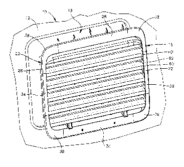
A grille for a vehicle wall opening may comprise a frame, a pair of first louvers, and a second louver. The frame may be receivable on the vehicle wall in an installed position extending around the opening, and may have an inboard side and an outboard side. The pair of first louvers may be supported on the frame, and may be transversely inclined to an outboard direction at a first angle. The second louver may be located between the first louvers, fixed relative to the first louvers, and inclined to the outboard direction at a second angle different from the first angle.


French Abstract

Une grille pour une ouverture de paroi de véhicule peut comprendre un cadre, une paire de premières persiennes et une seconde persienne. Le cadre peut être accueilli sur la paroi de véhicule, dans une position installée entourant louverture, et peut comporter un côté intérieur et un côté extérieur. La paire de premières persiennes peut être soutenue sur le cadre et peut être inclinée de façon transverse, dans une direction externe, selon un premier angle. La seconde persienne peut être située entre les premières persiennes, fixe par rapport aux premières persiennes et inclinée, dans une direction externe, selon un second angle différent du premier angle.

Claims

Note: Claims are shown in the official language in which they were submitted.


What is claimed is:
1. A grille for a vehicle wall opening, the grille comprising:
a frame receivable on the vehicle wall in an installed position extending
around the
opening, the frame having an inboard side and an outboard side;
a pair of first louvers supported on the frame, the first louvers being
transversely
inclined to an outboard direction at a first angle, each of the first louvers
having an outboard
edge; and
a second louver located between the first louvers, the second louver being
fixed
relative to the first louvers and inclined to the outboard direction at a
second angle different
from the first angle, the second louver having an inboard edge,
wherein, when the grille is oriented such that the outboard direction is
generally
horizontal, each of the first louvers reaches upward to the outboard edge at
the first angle, and
the second louver reaches upward from the inboard edge at the second angle.
2. The grille of claim 1, wherein the first and second louvers each have an
inboard edge
and an outboard edge, and the grille is free of a gap vertically between the
inboard edge of a
louver and the outboard edge of an adjacent louver when the grille is in an
upright
orientation.
3. The grille of claim 1 or 2 wherein the outboard direction is
perpendicular to a plane
between the inboard and outboard sides of the frame, and the second louver
blocks visibility
through the grille between the first louvers on a line of sight in the
outboard direction.
4. The grille of claim 1, wherein each of the first louvers further has an
inboard edge and
reaches vertically upward from the inboard edge.
5. The grille of claim 1, wherein the second louver further has an outboard
edge and
reaches vertically upward to the outboard edge.
6. The grille of any one of claims 1 to 5, further comprising additional
first louvers
transversely inclined to the outboard direction at the first angle, and
additional second louvers
located between adjacent first louvers, with each of the second louvers fixed
relative to the
first louvers and transversely inclined to the outboard direction at the
second angle.
- 5 -

7. The grille of any one of claims 1 to 6, wherein the first louvers and
the frame are
portions of a first part of the grille, and the second louver is a portion of
a second part of the
grille that is fastened to the first part.
8. A vehicle comprising:
a body including a cabin wall having a vent opening; and
a grille mounted on the cabin wall over the vent opening, the grille
comprising a
frame having an inboard side and an outboard side, a pair of first louvers
each having an
outboard edge, and a second louver located between the first louvers and
having an inboard
edge,
wherein the first louvers are transversely inclined to an outboard direction
at a first
angle, and the second louver is fixed relative to the first louvers and
transversely inclined to
the outboard direction at a second angle that differs from the first angle,
and
wherein, when the grille is oriented such that the outboard direction is
generally
horizontal, each of the first louvers reaches upward to the outboard edge at
the first angle, and
the second louver reaches upward from the inboard edge at the second angle.
9. The vehicle of claim 8, wherein the first and second louvers each have
an inboard
edge and an outboard edge, and the grille is free of a gap vertically between
the inboard edge
of a louver and the outboard edge of an adjacent louver when the grille is in
an upright
orientation.
10. The vehicle of claim 8 or 9 wherein the outboard direction is
perpendicular to a plane
between the inboard and outboard sides of the frame, and the second louver
blocks visibility
through the grille between the first louvers on a line of sight in the
outboard direction.
11. The vehicle of claim 8, wherein each of the first louvers further has
an inboard edge
and reaches vertically upward from the inboard edge.
12. The vehicle of claim 8, wherein the second louver further has an
outboard edge and
reaches vertically upward to the outboard edge.
- 6 -

13. The vehicle of any one of claims 8 to 11, wherein the vehicle is
selected from an
aircraft, a spacecraft, a land vehicle, and a marine vehicle.
14. A method comprising:
providing a grille for a decompression vent opening in a vehicle cabin wall,
the grille
including a frame configured to extend around the decompression vent opening,
and further
including louvers configured to direct air to flow though the grille under the
influence of a
pressure drop from an inboard side of the cabin wall to an outboard side,
the louvers including a pair of first louvers each having an outboard edge,
and a
second louver located between the first louvers and having an inboard edge,
wherein the first
louvers are transversely inclined to an outboard direction at a first angle,
and the second
louver is fixed relative to the first louvers and transversely inclined to the
outboard direction
at a second angle that differs from the first angle,
wherein, when the grille is oriented such that the outboard direction is
generally
horizontal, each of the first louvers reaches upward to the outboard edge at
the first angle, and
the second louver reaches upward from the inboard edge at the second angle.
15. The method of claim 14, further comprising providing additional first
louvers
transversely inclined to the outboard direction at the first angle, and
additional second louvers
located between adjacent first louvers, with each of the second louvers fixed
relative to the
first louvers and transversely inclined to the outboard direction at the
second angle.
- 7 -

Description

Note: Descriptions are shown in the official language in which they were submitted.


CA 02857696 2016-01-07
GRILLE FOR VEHICLE WALL OPENING
TECHNICAL FIELD
The present disclosure relates to a grille, and more particularly, to a grille
for a vehicle wall
opening.
BACKGROUND
An aircraft cabin sidewall is typically provided with decompression vent
openings. Each of
these vent openings may be covered by a grille that conceals the opening from
view. The
grille permits air to flow from the cabin outward through the opening in a
decompression
condition, and also attenuates noise generated by an ordinary return air flow
through the
grille. The air flow and noise control features of the grille may be provided
by an
arrangement of louvers on the grille.
SUMMARY
In an embodiment, there is provided a grille for a vehicle wall opening, the
grille comprising:
a frame receivable on the vehicle wall in an installed position extending
around the opening,
the frame having an inboard side and an outboard side; a pair of first louvers
supported on the
frame, the first louvers being transversely inclined to an outboard direction
at a first angle,
each of the first louvers having an outboard edge; and a second louver located
between the
first louvers, the second louver being fixed relative to the first louvers and
inclined to the
outboard direction at a second angle different from the first angle, the
second louver having
an inboard edge, wherein, when the grille is oriented such that the outboard
direction is
generally horizontal, each of the first louvers reaches upward to the outboard
edge at the first
angle, and the second louver reaches upward from the inboard edge at the
second angle.
In another embodiment, there is provided a vehicle comprising: a body
including a cabin wall
having a vent opening; and a grille mounted on the cabin wall over the vent
opening, the
grille comprising a frame having an inboard side and an outboard side, a pair
of first louvers
each having an outboard edge, and a second louver located between the first
louvers and
having an inboard edge, wherein the first louvers are transversely inclined to
an outboard
direction at a first angle, and the second louver is fixed relative to the
first louvers and
transversely inclined to the outboard direction at a second angle that differs
from the first

CA 02857696 2016-01-07
angle, and wherein, when the grille is oriented such that the outboard
direction is generally
horizontal, each of the first louvers reaches upward to the outboard edge at
the first angle, and
the second louver reaches upward from the inboard edge at the second angle.
In another embodiment, there is provided a method comprising: providing a
grille for a
decompression vent opening in a vehicle cabin wall, the grille including a
frame configured
to extend around the decompression vent opening, and further including louvers
configured
to direct air to flow though the grille under the influence of a pressure drop
from an inboard
side of the cabin wall to an outboard side, the louvers including a pair of
first louvers each
having an outboard edge, and a second louver located between the first louvers
and having an
inboard edge, wherein the first louvers are transversely inclined to an
outboard direction at a
first angle, and the second louver is fixed relative to the first louvers and
transversely inclined
to the outboard direction at a second angle that differs from the first angle,
wherein, when the
grille is oriented such that the outboard direction is generally horizontal,
each of the first
louvers reaches upward to the outboard edge at the first angle, and the second
louver reaches
upward from the inboard edge at the second angle.
The method may further comprise providing additional first louvers
transversely inclined to
the outboard direction at the first angle, and additional second louvers
located between
adjacent first louvers, with each of the second louvers fixed relative to the
first louvers and
transversely inclined to the outboard direction at the second angle.
Other objects and advantages of the disclosed grille will be apparent from the
following
description, the accompanying drawings and the appended claims.
- 2 -

CA 02857696 2016-01-07
BRIEF DESCRIPTION OF THE DRAWINGS
Figure 1 is an exploded perspective view of an embodiment of the disclosed
grille, taken
from an inboard side and shown with a vehicle cabin wall having a vent
opening.
Figure 2 is an exploded perspective view of parts of the grille embodiment of
Fig. 1, taken
from an outboard side.
Figure 3 is a side view, partly in section, of a part of the grille embodiment
of Fig. 1.
Figure 4 is a side view, partly in section, of another part of the grille
embodiment of Fig. 1.
Figure 5 is a side view, partly in section, of the grille embodiment of Fig.
1.
DETAILED DESCRIPTION
As shown partially in Fig. 1, a vehicle body 10 may have a wall 12 with an
opening 15. A
grille 16 may be provided over the opening 15. The vehicle may be, for
exarnple, an aircraft,
a spacecraft, a land vehicle or a marine vehicle. In the illustrated
embodiment, the vehicle is
an aircraft in which the wall 12 is a cabin sidewall, and the opening 15 is a
decompression
vent opening.
- 2a -

CA 02857696 2014-07-23
An embodiment of the grille 16 may include a frame 20. As viewed at an inboard
side 22 in
Fig. 1, the frame 20 may have a rectangular rim 26 with upper and lower side
sections 28 and
30, left and right end sections 34 and 36, and rounded corners 38. As viewed
at an outboard
side 42 in Fig. 2, the frame 20 may also have a flange 44 projecting rearward
from an inner
edge 46 of the rim 26. Mounting structures in the foini of tabs 50 may be
provided at upper
side section 28 of the frame 20, with additional mounting structures in the
form of brackets
52 for fastener clips at the lower side section 30. Such tabs 50 and brackets
52 are configured
for mounting the frame 20 on the cabin sidewall 12 in a known manner.
An array of first louvers 60 may be provided on the frame 20. The first
louvers 60 and the
frame 20 may be provided as portions of a unitary part which is free of joined
parts. Such a
unitary part may be, for example, a continuous body of material such as
injection molded
plastic. The first louvers 60 and the frame 20 may alternatively be provided
as portions of an
assembled part that includes joined parts, any one or more of which could be
unitary.
The first louvers 60 may be oriented longitudinally in parallel directions
extending across the
frame 20 between the opposite end sections 34 and 36. The first louvers 60 may
also be
transversely inclined to an outboard direction through the grille 16. For
example, an outboard
direction through the grille 16 is indicated by the arrow 63 in Fig. 3. The
outboard direction
63 in this example is perpendicular to a plane 65 between the inboard and
outboard sides 22
and 42 of the frame 20. In the illustrated embodiment of the grille 16, the
plane 65 extends
vertically across the frame 20 between the upper and lower side sections 28
and 30, and
extends horizontally across the frame 20 between the left and end sections 34
and 36.
More specifically, as shown in Fig. 3, each of the first louvers 60 may have
an inboard edge
66 and an outboard edge 68. A width portion 70 of each first louver 60 may
reach vertically
upward from the inboard edge 66. Each first louver 60 may also have a width
portion 72 that
is inclined upward to the outboard edge 68. The first louvers 60 may thus be
transversely
inclined to the outboard direction 63 at a first angle Al.
An embodiment of the grille 16 may further include a grid 80. As shown in Fig.
2, the grid
80 may include second louvers 82 supported by stiffeners 84. The second
louvers 82 and the
stiffeners 84 may be provided as portions of a unitary part or an assembled
part, as described
above with reference to the first louvers 60 and the frame 20.
-3 -

CA 02857696 2014-07-23
The stiffeners 84 may be oriented vertically when the grid 80 is in the
upright position shown
in Fig. 4, with the second louvers 82 reaching horizontally across the
stiffeners 84. A width
section 88 of each second louver 82 may be inclined upward from an inboard
edge 90 such
that each second louver 82 is transversely inclined to the outboard direction
63. In a
preferred embodiment, the second louvers 82 may be inclined at a second angle
A2 that
differs from the first angle Al. Each second louver 82 may also have another
width section
92 that reaches vertically upward to an outboard edge 94.
The stiffeners 84 may be configured for attachment of the grid 80 to the frame
20 in the
assembled arrangement shown in Fig. 5. This may be accomplished by attachment
bores 96
for receiving attachment posts 98 on the frame 20. The stiffeners 84 may also
have posts 100
and tabs 102 for engaging retainers 104 and slots 105 on a baffle 106 that is
mounted on the
inboard side 22 of the grille 16. When the grid 80 is attached to the frame
20, the second
louvers 82 on the grid 80 are fixed relative to the first louvers 60 on the
frame 20.
As shown in Fig. 5, the first louvers 60 are vertically spaced apart from one
another to define
air flow paths through the grille 16. Each of the second louvers 82 is located
between a pair
of adjacent first louvers 60, which interposes the second angle of inclination
A2 between
each adjacent pair of the first angles of inclination Al. In the event of
decompression of the
aircraft cabin, a pressure drop through the opening 15 induces a flow of air
through the grille
16 along the flow paths between the louvers 60 and 82. The differing angles of
inclination
A1 and A2 help to attenuate the generation of noise along those air flow
paths. The sound
attenuating effect may be enhanced where the grille 16, when in an upright
orientation as
shown in Fig. 5, has no vertical gap between the inboard edge of a louver and
the outboard
edge of an adjacent louver. This structural feature also improves the
appearance of the
installed grille 16, as each second louver 82 blocks visibility through the
grille 16 between
the adjacent first louvers 60 on a line of sight in the outboard direction 63.
While the methods and foi __ ins of apparatus disclosed herein may constitute
preferred aspects
of the disclosed grille, it is to be understood that the invention is not
limited to these precise
forms and methods, and that changes may be made therein without departing form
the scope
of the invention.
- 4 -

Representative Drawing
A single figure which represents the drawing illustrating the invention.
Administrative Status

2024-08-01:As part of the Next Generation Patents (NGP) transition, the Canadian Patents Database (CPD) now contains a more detailed Event History, which replicates the Event Log of our new back-office solution.

Please note that "Inactive:" events refers to events no longer in use in our new back-office solution.

For a clearer understanding of the status of the application/patent presented on this page, the site Disclaimer , as well as the definitions for Patent , Event History , Maintenance Fee  and Payment History  should be consulted.

Event History

Description Date
Maintenance Request Received 2024-07-19
Maintenance Fee Payment Determined Compliant 2024-07-19
Inactive: COVID 19 - Deadline extended 2020-07-16
Common Representative Appointed 2019-10-30
Grant by Issuance 2017-01-03
Inactive: Cover page published 2017-01-02
Pre-grant 2016-11-21
Inactive: Final fee received 2016-11-21
Letter Sent 2016-05-26
Notice of Allowance is Issued 2016-05-26
Inactive: Q2 passed 2016-05-18
Inactive: Approved for allowance (AFA) 2016-05-18
Amendment Received - Voluntary Amendment 2016-01-07
Inactive: S.30(2) Rules - Examiner requisition 2015-07-08
Inactive: Report - No QC 2015-06-30
Inactive: Cover page published 2015-03-30
Application Published (Open to Public Inspection) 2015-03-24
Inactive: IPC assigned 2014-08-29
Inactive: First IPC assigned 2014-08-29
Inactive: IPC assigned 2014-08-28
Letter Sent 2014-08-06
Inactive: Filing certificate - RFE (bilingual) 2014-08-06
Filing Requirements Determined Compliant 2014-08-06
Application Received - Regular National 2014-07-25
Inactive: Pre-classification 2014-07-23
Inactive: QC images - Scanning 2014-07-23
All Requirements for Examination Determined Compliant 2014-07-23
Request for Examination Requirements Determined Compliant 2014-07-23

Abandonment History

There is no abandonment history.

Maintenance Fee

The last payment was received on 2016-07-08

Note : If the full payment has not been received on or before the date indicated, a further fee may be required which may be one of the following

  • the reinstatement fee;
  • the late payment fee; or
  • additional fee to reverse deemed expiry.

Patent fees are adjusted on the 1st of January every year. The amounts above are the current amounts if received by December 31 of the current year.
Please refer to the CIPO Patent Fees web page to see all current fee amounts.

Fee History

Fee Type Anniversary Year Due Date Paid Date
Application fee - standard 2014-07-23
Request for examination - standard 2014-07-23
MF (application, 2nd anniv.) - standard 02 2016-07-25 2016-07-08
Final fee - standard 2016-11-21
MF (patent, 3rd anniv.) - standard 2017-07-24 2017-07-18
MF (patent, 4th anniv.) - standard 2018-07-23 2018-07-16
MF (patent, 5th anniv.) - standard 2019-07-23 2019-07-19
MF (patent, 6th anniv.) - standard 2020-07-23 2020-07-17
MF (patent, 7th anniv.) - standard 2021-07-23 2021-07-16
MF (patent, 8th anniv.) - standard 2022-07-25 2022-07-15
MF (patent, 9th anniv.) - standard 2023-07-24 2023-07-14
MF (patent, 10th anniv.) - standard 2024-07-23 2024-07-19
Owners on Record

Note: Records showing the ownership history in alphabetical order.

Current Owners on Record
THE BOEING COMPANY
Past Owners on Record
FRED P. SIEBERT
LON E. SWITZER
Past Owners that do not appear in the "Owners on Record" listing will appear in other documentation within the application.
Documents

To view selected files, please enter reCAPTCHA code :


To view images, click a link in the Document Description column. To download the documents, select one or more checkboxes in the first column and then click the "Download Selected in PDF format (Zip Archive)" or the "Download Selected as Single PDF" button.

List of published and non-published patent-specific documents on the CPD .

If you have any difficulty accessing content, you can call the Client Service Centre at 1-866-997-1936 or send them an e-mail at CIPO Client Service Centre.


Document
Description 
Date
(yyyy-mm-dd) 
Number of pages   Size of Image (KB) 
Description 2014-07-22 4 207
Claims 2014-07-22 3 121
Abstract 2014-07-22 1 14
Drawings 2014-07-22 3 94
Representative drawing 2015-02-17 1 26
Description 2016-01-06 5 227
Claims 2016-01-06 3 120
Representative drawing 2016-12-13 1 29
Confirmation of electronic submission 2024-07-18 3 79
Acknowledgement of Request for Examination 2014-08-05 1 176
Filing Certificate 2014-08-05 1 206
Reminder of maintenance fee due 2016-03-23 1 111
Commissioner's Notice - Application Found Allowable 2016-05-25 1 163
Examiner Requisition 2015-07-07 3 192
Amendment / response to report 2016-01-06 10 350
Final fee 2016-11-20 2 69