Note: Descriptions are shown in the official language in which they were submitted.
CA 02858895 2014-06-10
WO 2013/090305 PCT/US2012/069048
DYNAMIC CHANNEL BONDING
PARTIAL SERVICE TRIGGERING
BACKGROUND
[0001] Data over cable service interface specification (DOCSIS) is an
international
telecommunications standard that permits the addition of high-speed data
transfer to
an existing cable television system. To maintain cross-version compatibility
across all
versions of DOCSIS, cable television operators utilize cable modems that
support
DOCSIS 1.X, 2.X, and 3.0, and that fall back to the highest supported version
in
common between both endpoints. Cable television operators use DOCSIS 3.0 to
provide two-way communication over their existing hybrid fiber-coaxial (HFC)
infrastructure.
[0002] An HFC network is a broadband network that combines optical fiber and
coaxial cable. The HFC network is a two-way communication network between a
cable modem termination system (CMTS) and a cable modem. The CMTS is
communication equipment typically located in a cable operator's headend
facility. The
CMTS collects and processes communication signals, distributes those signals
to
customer locations using downstream channels, and receives other communication
signals from the customer locations on upstream channels. The cable modem is a
communication device that receives the communication signals on the downstream
channels from the CMTS, and transmits the other communication signals to the
CMTS on the upstream channels. The cable modem may be a standalone device that
connects to the Internet, or integrated with a set-top box.
¨ 1 ¨
CA 02858895 2014-06-10
WO 2013/090305 PCT/US2012/069048
[0003] The DOCSIS 1.X and 2.X specifications describe the channel frequency
and
modulation characteristics for downstream and upstream transmissions. When the
CMTS communicates with a device, the DOCSIS 1.X or 2.X cable modem at a
customer location uses the frequencies (channels) of the CMTS transmitter and
receiver to which the modem is physically connected to carry the downstream
and
upstream transmissions. The term "channel" as used herein is synonymous with
the
term "receiver". If the channel becomes impaired, the modulation mode of the
channel can drop, resulting in a reduction in the bandwidth to the device.
[0004] Channel bonding is a DOCSIS 3.0 feature that enables a DOCSIS 3.0 cable
modem at a customer location to use multiple downstream channels, or multiple
upstream channels, together at the same time. For example, a cable modem
configured with four upstream channels can use DOCSIS 3.0 channel bonding to
increase the throughput of the upstream communication with the CMTS. The cable
modem distributes, or segments, the data packets among the four channels in an
upstream bonding group and transmits the data packets to the CMTS in parallel,
rather
than in series. When the upstream bonding group operates in full service mode,
the
CMTS receives and reassembles the data packets on all four channels in the
upstream
bonding group. If there is a problem receiving data packets on a CMTS
receiver, due
to an upstream channel that is associated with the receiver being impaired or
unavailable, the CMTS cannot properly reassemble the data packets for the
upstream
bonding group and data loss or throughput degradation will result. The
detection of
this problem will allow communication to continue between the CMTS and cable
modem by transitioning the upstream bonding group to operate in partial
service
mode by disabling data grant scheduling on the faulty receiver/channel.
¨ 2 ¨
CA 02858895 2014-06-10
WO 2013/090305 PCT/US2012/069048
[0005] When DOCSIS 1.X, 2.X, and 3.0 modems are registered to use a channel
that
becomes impaired, a decrease in bandwidth on the impaired channel, which can
also
result from a lowering of the modulation profile due to noise, is a greater
impact on
the DOCSIS 1.X and 2.X modems, because the DOCSIS 3.0 modem has other bonded
channels to use for data passing as long as the impaired channel is in partial
service
mode. If the DOCSIS 3.0 modem is not yet in partial service mode, the DOCSIS
3.0
modem cannot reassemble the packets. In addition, the reduction in bandwidth
may
cause an increase in utilization based on the bandwidth size, and may trigger
unnecessary load balancing with the possibility of losing modems when they
attempt
to move to another channel. Furthermore, a configuration change by the cable
operator may cause a decrease in the modulation mode. There is a need for a
method
of controlling when a channel transitions to partial service mode to make
valuable
bandwidth available for other resources. The presently disclosed invention
satisfies
this demand.
SUMMARY
[0006] Aspects of the present invention provide a method and computing device
for
transitioning into and out of partial service mode to make valuable bandwidth
available for other resources. The method sets a trigger value for a channel,
where a
first cable modem and a second cable modem have registered to use the channel,
and
where the first cable modem is a bonded channel modem that utilizes a bonding
group
that includes the channel and at least one other channel. The method then
monitors a
modulation mode for the channel. The method transitions the channel from full
service mode to partial service mode when the channel is in full service mode
and the
monitoring detects that the modulation mode is less than or equal to the
trigger value.
The method transitions the channel from partial service mode to full service
mode
¨ 3 ¨
CA 02858895 2014-06-10
WO 2013/090305 PCT/US2012/069048
when the channel is in partial service mode and the modulation mode for the
channel
is greater than the trigger value.
BRIEF DESCRIPTION OF THE DRAWINGS
[0007] FIG. 1 is a block diagram that illustrates one embodiment of the
hardware
components of a system that performs the present invention.
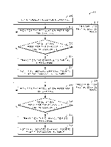
[0008] FIG. 2 is a flow diagram that illustrates a method of transitioning
into and out
of partial service mode to make valuable bandwidth available for other
resources
according to one embodiment of the present invention.
DETAILED DESCRIPTION
[0009] FIG. 1 is a block diagram that illustrates one embodiment of the
hardware
components of a system that performs the present invention. A broadband
network
100 includes an Internet protocol (IP) network 110, cable modem termination
system
(CMTS) 120, cable network 130, customer location A 140, customer location B
180,
and customer location C 190. The broadband network 100 shown in FIG. 1 may
include any number of interconnected IP network 110, CMTS 120, cable network
130,
customer location A 140, customer location B 180, and customer location C 190
components.
[0010] The IP network 110 shown in FIG. 1, in one embodiment, is a public
communication network or wide area network (WAN) that connects to the CMTS
120. The present invention also contemplates the use of comparable network
architectures including a LAN, a personal area network (PAN) such as a
Bluetooth
¨ 4 ¨
CA 02858895 2014-06-10
WO 2013/090305 PCT/US2012/069048
network, a wireless LAN (e.g., a wireless-fidelity (Wi-Fi) network), peer-to-
peer
overlay network, and a virtual private network (VPN). The system contemplates
comparable network architectures and protocols such as Ethernet and
transmission
control protocol.
[0011] The cable network 130 shown in FIG. 1, in one embodiment, is a hybrid
fiber-
coaxial (HFC) network. The cable network 130 is a data and video content
network
that provides two-way communication between the CMTS 120 and customer location
A 140, customer location B 180 or customer location C 190. The downstream
communication path is from the CMTS 120 to a customer location (e.g., customer
location A 140, customer location B 180, or customer location C 190). The
upstream
communication path is from a customer location (e.g., customer location A 140,
customer location B 180, or customer location C 190) to the CMTS 120.
[0012] The CMTS 120, in one embodiment, is communication equipment located in
a
cable operator's headend or hubsite that provides high-speed data services,
such as
cable Internet or voice over Internet protocol, to cable subscribers. The CMTS
120
shown in FIG. 1 includes at least one computing device, each having one or
more
processors, that provides customer location A 140, customer location B 180,
and
customer location C 190 with various services and connections. This includes
support
for data over cable service interface specification (DOCSIS) 122 services
(e.g.,
DOCSIS 1.X, DOCSIS 2.X, and DOCSIS 3.0), partial service triggering program
124,
channel trigger values 126, IP network 110 connections, and cable network 130
connections. The partial service triggering program 124 and channel trigger
values
126, together with the cable modem 142, performs the method of the present
invention disclosed in the exemplary embodiments depicted in FIG. 2. The IP
network
110 connections enable the CMTS 120 to provide access to external services
such as
¨ 5 ¨
CA 02858895 2014-06-10
WO 2013/090305 PCT/US2012/069048
video servers, public switched telephone network voice, multimedia messages,
and
Internet data.
[0013] Customer location A 140 shown in FIG. 1 is a customer's home, business,
or
another location where the customer accesses the cable service. In one
embodiment,
customer location A 140 includes a cable modem 142, set-top box 144, and
display
device 146. In other embodiments, the set-top box 144 is a digital television
(DTV)
Converter (DTC) or other customer-premises equipment (CPE), and the display
device 146 is an Internet protocol television (IPTV) or analog television. In
yet
another embodiment, the set-top box 144 includes the cable modem 142.
[0014] The cable modem 142 shown in FIG. 1, in one embodiment, is a general-
purpose computing device that performs the present invention together with the
partial service triggering program 124 and channel trigger values 126 on the
CMTS
120. A bus 150 is a communication medium connecting a processor 155, data
storage
device 160 (such as a serial ATA (SATA) hard disk drive, optical drive, small
computer system interface (SCSI) disk, flash memory, or the like),
communication
interface 165, and memory 170 (such as random access memory (RAM), dynamic
RAM (DRAM), non-volatile computer memory, flash memory, or the like). The
communication interface 165 connects the cable modem 142 to the cable network
130
and allows for two-way communication of data and content. In one embodiment,
the
set-top box 144 includes the cable modem 142 implemented as an application-
specific
integrated circuit (ASIC).
[0015] The processor 155 performs the disclosed methods by executing sequences
of
operational instructions that comprise each computer program resident in, or
operative
on, the memory 170. The reader should understand that the memory 170 may
include
¨ 6 ¨
CA 02858895 2014-06-10
WO 2013/090305
PCT/US2012/069048
operating system, administrative, and database programs that support the
programs
disclosed in this application. In one embodiment, the configuration of the
memory
170 of the cable modem 142 includes a DOCSIS 3.0 program 172. The DOCSIS 3.0
program 172 is an implementation of DOCSIS 3.0 that, together with the partial
service triggering program 124 and channel trigger values 126, performs the
method
of the present invention disclosed in the exemplary embodiments depicted in
FIG. 2.
When the processor 155 performs the disclosed method, it stores intermediate
results
in the memory 170 or data storage device 160. In another embodiment, the
processor
155 may swap these programs, or portions thereof, in and out of the memory 170
as
needed, and thus may include fewer than all of these programs at any one time.
[0016] Customer location B 180 shown in FIG. 1 is a customer's home, business,
or
another location where the customer accesses the cable service. In one
embodiment,
customer location B 180 includes hardware components (not shown) similar to
those
shown in customer location A 140. The only difference is that customer
location B
180 includes a DOCSIS 1.1 modem 182 that implements the DOCSIS 1.1
specification to replace the cable modem 142 that implements the DOCSIS 3.0
specification in customer location A 140.
[0017] Customer location C 190 shown in FIG. 1 is a customer's home, business,
or
another location where the customer accesses the cable service. In one
embodiment,
customer location C 190 includes hardware components (not shown) similar to
those
shown in customer location A 140. The only difference is that customer
location C
190 includes a DOCSIS 2.0 modem 192 that implements the DOCSIS 2.0
specification to replace the cable modem 142 that implements the DOCSIS 3.0
specification in customer location A 140.
¨ 7 ¨
CA 02858895 2014-06-10
WO 2013/090305 PCT/US2012/069048
[0018] FIG. 2 is a flow diagram that illustrates a method of transitioning
into and out
of partial service mode to make valuable bandwidth available for other
resources
according to one embodiment of the present invention. In one embodiment, the
present invention can apply to upstream channels only. In another embodiment,
the
present invention can apply to downstream channels only. In yet another
embodiment,
the present invention can apply to either upstream channels or downstream
channels,
or to both upstream channels and downstream channels.
[0019] The process 200 shown in FIG. 2 begins when the CMTS 120 sets a trigger
value for a channel (step 205). In one embodiment, a cable operator sends a
configuration parameter to the CMTS 120 that causes the CMTS 120 to store a
trigger
value for a specified upstream or downstream channel. Once the trigger value
is set,
the process 200 determines when to trigger into partial service mode (step
210), and
when to trigger out of partial service mode (step 235).
[0020] To determine when to trigger into partial service mode (step 210), the
process
200 monitors the modulation mode for the channel (step 215). In one
embodiment, the
modulation mode for the channel is whether the channel is operating in 64 QAM,
32
QAM, 16 QAM or 8 QAM, and the trigger value is 16 QAM. In other embodiments,
the present invention contemplates other modulation modes for the channel
(e.g., 256
QAM, 128 QAM, and the like), other modulation modes for a spectrum group, and
priorities for a modulation profile hopping rule. While the modulation mode
for the
channel is greater than the trigger value (step 220, N branch), the process
200
continues to monitor the modulation mode for the channel (step 215). When the
modulation mode for the channel is less than or equal to the trigger value
(step 220, Y
branch), the process 200 transitions the channel to partial service mode (step
225).
¨ 8 ¨
CA 02858895 2014-06-10
WO 2013/090305 PCT/US2012/069048
The process 200 then notifies all bonded channel modems (i.e., DOCSIS 3.0
modems)
that the channel is unusable (step 230).
[0021] To determine when to trigger out of partial service mode (step 235),
the
process 200 monitors the modulation mode for the channel (step 240). While the
modulation mode for the channel is less than or equal to the trigger value
(step 245, N
branch), the process 200 continues to monitor the modulation mode for the
channel
(step 240). When the modulation mode for the channel is greater than the
trigger value
(step 245, Y branch), the process 200 transitions the channel to full service
mode (step
250). The process 200 then notifies all bonded channel modems (i.e., DOCSIS
3.0
modems) that the channel is usable (step 255).
[0022] In the method shown in FIG. 2, the purpose of transitioning into
partial service
mode is to free valuable bandwidth for DOCSIS 1.X and 2.X modems, while
temporarily transitioning DOCSIS 3.0 bonded channel modems into partial
service.
The purpose of transitioning back to full service mode is to allocate
available valuable
bandwidth for DOCSIS 3.0 bonded channel modems. The trigger value is a
configuration parameter for transitioning into and out of partial service
mode. In one
embodiment, the cable operators are provided the trigger value, thereby giving
them
full control of this functionality. The configuration parameter allows the
cable
operator to select a modulation mode used to trigger the transition into and
out of
partial service mode for a particular channel. In various embodiments, the
configuration parameter is a modulation mode per channel association, a
modulation
mode configurable per spectrum group, and the modification of a priority of an
existing modulation profile hopping rule. Furthermore, the configuration
parameter
has a setting that disables the functionality if the cable operator does not
want to use
it.
¨ 9 ¨
CA 02858895 2014-06-10
WO 2013/090305 PCT/US2012/069048
[0023] The following two examples illustrate the method of transitioning into
and out
of partial service mode shown in FIG. 2 in which a DOCSIS 1.1 modem, DOCSIS
2.0
modem, and DOCSIS 3.0 modem have registered to use an upstream channel. The
first example illustrates the impact on the bandwidth to the DOCSIS 1.1 modem,
DOCSIS 2.0 modem, and DOCSIS 3.0 modem when the innovation of the present
invention is disabled. The second example illustrates the improvements
realized when
the innovation of the present invention is enabled. Finally, even though these
examples focus on an upstream channel, one skilled in the art will realize
that these
examples are easily adaptable to downstream channels.
[0024] With the innovation of the present invention disabled, a DOCSIS 1.1
modem
182, DOCSIS 2.0 modem 192, and DOCSIS 3.0 cable modem 142 registers to use an
upstream channel on the CMTS 120. The channel is operating in 64 QAM
modulation
mode with spare hopping modulation modes such as 32 QAM, 16 QAM, and 8 QAM.
When the channel becomes impaired and the modulation mode drops to 16 QAM,
this
greatly reduces the available bandwidth for all modems, especially the DOCSIS
1.1
modem 182 and DOCSIS 2.0 modem 192. Since the DOCSIS 3.0 cable modem 142 is
bonded, it still has other channels to use for data passing and only takes a
small
overall bandwidth hit. If the channel becomes more impaired and the modulation
mode drops to 8 QAM, the DOCSIS 1.1 modem 182 and DOCSIS 2.0 modem 192 are
really limited in their ability to pass data, but the DOCSIS 3.0 cable modem
142 still
has other channels to use. If the channel impairment is bad enough, the DOCSIS
1.1
modem 182 and DOCSIS 2.0 modem 192 may not be able to pass data or even stay
registered because there is not enough bandwidth to support all of the ranging
requests. The reduction of bandwidth (causing an increase in utilization based
on
bandwidth size) may also trigger unnecessary load balancing with the
possibility of
losing modems when they attempt to move to another channel. If the channel
¨ 10 ¨
CA 02858895 2014-06-10
WO 2013/090305 PCT/US2012/069048
impairment then goes away and the modulation mode for the channel increases to
64
QAM, the channel may now be underutilized if the modems were moved by load
balancing. In addition, since the DOCSIS 1.1 modem 182 and DOCSIS 2.0 modem
192 also carry voice traffic, the reduction of bandwidth may also result in
dropping
voice calls or the failure to initiate a voice call.
[0025] With the innovation of the present invention enabled, a DOCSIS 1.1
modem
182, DOCSIS 2.0 modem 192, and DOCSIS 3.0 cable modem 142 registers to use an
upstream channel on the CMTS 120. The channel is operating in 64 QAM
modulation
mode with spare hopping modulation modes such as 32 QAM, 16 QAM, and 8 QAM.
The cable operator configures the partial service mode trigger value for the
channel to
be 16 QAM. When the channel becomes impaired and the modulation mode drops to
16 QAM, the present invention will transition the channel into partial service
mode.
This means the channel is marked as unusable for all bonded modems using it,
such as
the DOCSIS 3.0 cable modem 142. The bonded modems still have multiple channels
to pass data on. Now all the bandwidth that the DOCSIS 3.0 cable modem 142 was
using is now available for use by the DOCSIS 1.1 modem 182 and DOCSIS 2.0
modem 192. If the channel becomes more impaired and the modulation mode drops
to
8 QAM, the present invention does not place the DOCSIS 1.1 modem 182 and
DOCSIS 2.0 modem 192 in as much danger of being dropped with the reduction of
bandwidth because the bonded modems are not using the channel. If the channel
impairment decreases and the modulation mode only goes back to 16 QAM, the
DOCSIS 3.0 cable modem 142 is still not able to use the channel but there is
more
bandwidth for the DOCSIS 1.1 modem 182 and DOCSIS 2.0 modem 192. If the
channel impairment then goes away and the modulation mode for the channel goes
back to 64 QAM, the channel comes out of partial service because the
modulation
mode is greater than the trigger mode and the bonded modems are able to reuse
the
¨ 11 ¨
CA 02858895 2014-06-10
WO 2013/090305 PCT/US2012/069048
channel again. Thus, there was no unnecessary load balancing or fear of losing
modems in the move. In addition, voice calls on the DOCSIS 1.1 modem 182 and
DOCSIS 2.0 modem 192 were probably not affected. The DOCSIS 3.0 cable modem
142 still had multiple channels to use and the DOCSIS 1.1 modem 182 and DOCSIS
2.0 modem 192 had their share of bandwidth.
[0026] The modulation modes do not have to hit exactly on the trigger value
for the
channel or configured modulation mode. If the channel goes from 64 QAM to 8
QAM
with a trigger value of 16 QAM, then the channel goes into partial service
because the
active modulation mode went below the trigger value. The same holds true for
coming
out of partial service. If the channel goes from 8 QAM to 32 QAM it comes out
of
partial service because the active modulation mode is better than the trigger
mode.
[0027] Although the disclosed embodiments describe a fully functioning method
and
computing device of transitioning into and out of partial service mode to make
valuable bandwidth available for other resources, the reader should understand
that
other equivalent embodiments exist. Since numerous modifications and
variations will
occur to those reviewing this disclosure, the method and computing device of
transitioning into and out of partial service mode to make valuable bandwidth
available for other resources is not limited to the exact construction and
operation
illustrated and disclosed. Accordingly, this disclosure intends all suitable
modifications and equivalents to fall within the scope of the claims.
¨ 12 ¨