Note: Descriptions are shown in the official language in which they were submitted.
CA 02859347 2016-01-08
DOWNHOLE SYSTEMS AND METHODS FOR WATER SOURCE
DETERMINATION
TECHNICAL FIELD
[0000] The present application generally relates to a system and a method for
measuring an analyte
concentration in a downhole fluid.
BACKGROUND
[0001] After a
wellbore has been drilled, the wellbore typically is cased by inserting
lengths of
steel pipe ("casing sections") connected end-to-end into the wellbore.
Threaded exterior rings called
couplings or collars are typically used to connect adjacent ends of the casing
sections at casing joints.
The result is a "casing string" including casing sections and connecting
collars that extends from the
surface to a bottom of the wellbore. The casing string is then cemented in
place to complete the
casing operation. After a wellbore is cased, the casing is often perforated to
provide access to one or
more desired formations, e.g., to enable fluid from the formation(s) to enter
the wellbore.
[0002]
Hydraulic fracturing is an operating technique where a fracturing fluid,
typically water with
selected additives, is pumped into a completed well under high pressure. The
high pressure fracturing
fluid causes fractures to form and propagate within the surrounding geological
formation, making it
easier for formation fluids to reach the wellbore. After the fracturing is
complete, the pressure is
reduced, allowing most of the fracturing fluid to flow back into the well.
Some residual amount of the
fracturing fluid may be expected to remain in the surrounding formation and
perhaps flow back to the
well over time as other fluids are produced from the formation. The volume and
return rate of the
fracturing fluid is indicative of the physical structure of the created
fractures as well as the effective
permeability for the newly-fractured completion zone.
[0003] During
normal operations, the well produces a combination of fluids, typically
including a
desired hydrocarbon fluid (e.g., oil or gas) and water (i.e., "produced
water"). The produced water
can originate from multiple sources such as connate water from different
formation layers, fracturing
fluid, water injected from a remote well and/or steam injected from a remote
well. These latter
examples are typical of a steam or water flooding operation designed to force
hydrocarbons to flow to
the producing well.
[0004] In order
to monitor and optimize hydraulic fracturing operations, and to better
understand
the relative permeabilities and physical structures of fractures resulting
from hydraulic fracturing, it
would be beneficial to determine the sources of water produced from each
completion zone. For
steam operations such as Steam-Assisted Gravity Drainage (SAGD) and water
flooding operations,
there is likewise a need to assess steam and
water
- 1 -
CA 02859347 2014-06-04
WO 2013/137992 PCT/US2013/024845
sweep areas. Despite these apparent benefits, there exists a need for improved
systems or
methods for such determinations.
BRIEF DESCRIPTION OF THE DRAWINGS
[0005] Accordingly, there are disclosed in the drawings and the following
description
specific examples of downhole systems and methods for water source
determination. In the
drawings:
[0006] Fig. 1 is a side elevation view of an illustrative downhole water
source sensing
system in a production well;
[0007] Fig. 2 is a diagram of an illustrative fiber optic cable and optical
sensing system;
[0008] Figs. 3-4 show alternative downhole water source sensing system
embodiments;
[0009] Figs. 5A-5C show illustrative distributed downhole species sensing
techniques; and
[0010] Fig. 6 is a flowchart of an illustrative method for determining sources
of water in a
downhole fluid.
[0011] It should be understood, however, that the specific embodiments given
in the
drawings and detailed description thereof do not limit the disclosure. On the
contrary, they
provide the foundation for one of ordinary skill to discern the alternative
forms, equivalents,
and modifications that are encompassed together with one or more of the given
embodiments
in the scope of the appended claims.
DETAILED DESCRIPTION
[0012] Turning now to the figures, Fig. 1 shows a production well 10 equipped
with an
illustrative downhole water source sensing system 12. The well 10 shown in
Fig. 1 has been
constructed and completed in a typical manner, and it includes a casing string
14 positioned
in a borehole 16 that has been formed in the earth 18 by a drill bit. The
casing string 14
includes multiple tubular casing sections (usually about 30 foot long)
connected end-to-end
by couplings. One such coupling is shown in Fig. 1 and labeled `20.' Within
the well 10,
cement 22 has been injected between an outer surface of the casing string 14
and an inner
surface of the borehole 16 and allowed to set. A production tubing string 24
has been
positioned in an inner bore of the casing string 14.
[0013] The well 10 is adapted to guide a desired fluid (e.g., oil or gas) from
a bottom of the
borehole 16 to the surface of the earth 18. Perforations 26 have been formed
at a bottom of
the borehole 16 to facilitate the flow of a fluid 28 from a surrounding
formation (i.e., a
"formation fluid") into the borehole and thence to the surface via an opening
30 at the bottom
-2-
CA 02859347 2014-06-04
WO 2013/137992 PCT/US2013/024845
of the production tubing string 24. Though only one perforated zone is shown,
many
production wells may have multiple such zones, e.g., to produce fluids from
different
formations.
[0014] The fluid 28 produced by the well includes the desired fluid (e.g., oil
or gas) along
with water (i.e., "produced water") originating from one or more sources. For
example, the
water in the produced fluid 28 may be a mixture of water from the surrounding
formation
(i.e., "formation water" such as connate water) and fracturing fluid
previously pumped into
the surrounding formation under high pressure via the production tubing string
24.
Alternately, or in addition, the produced water may include water from other
formations, or
injected water from injection wells (e.g., flood fluid from a remote well). It
is noted that the
configuration of well 10 in Fig. 1 is illustrative and not limiting on the
scope of the
disclosure.
[0015] As described in more detail below, the downhole optical sensor system
12 is adapted
to detect concentration(s) of one or more chemical species in the produced
fluid 28. In some
embodiments, the detected chemical species are known to be present in one or
more sources
of water contributing to the produced water in the fluid 28. In these
embodiments, the
downhole optical sensor system 12 makes it possible to determine a portion of
the produced
water originating from a given one of multiple potential sources of water. For
example, the
downhole optical sensor system 12 may be adapted to determine a portion of the
produced
water originating from fracturing fluid. This information can advantageously
be used to
monitor and optimize hydraulic fracturing operations, and to better understand
the relative
permeabilities and physical structures of fractures resulting from hydraulic
fracturing.
[0016] In the embodiment of Fig. 1, the downhole optical sensor system 12
includes an
optical sensor 40 in contact with the fluid 28 at the bottom of the borehole
16 and coupled to
an interface 42 via a fiber optic cable 44. The interface 42 may be located on
the surface of
the earth 18 near the wellhead, i.e., a "surface interface". The optical
sensor 40 includes a
waveguide and is adapted to alter light passing through the waveguide
dependent upon a
concentration of one or more chemical species in the fluid 28.
[0017] In the embodiment of Fig. 1, the fiber optic cable 44 extends along an
outer surface
of the casing string 14 and is held against the outer surface of the of the
casing string 14 at
spaced apart locations by multiple bands 46 that extend around the casing
string 14. A
protective covering may be installed over the fiber optic cable 44 at each of
the couplings of
the casing string 14 to prevent the cable from being pinched or sheared by the
coupling's
contact with the borehole wall. In Fig. 1, a protective covering 48 is
installed over the fiber
-3-
CA 02859347 2014-06-04
WO 2013/137992 PCT/US2013/024845
optic cable 44 at the coupling 20 of the casing string 14 and is held in place
by two of the
bands 46 installed on either side of coupling 20.
[0018] In at least some embodiments, the fiber optic cable 44 terminates at
surface interface
42 with an optical port adapted for coupling the fiber optic cable to a light
source and a
detector. The light source transmits light along the fiber optic cable to the
optical sensor 40,
which alters the light to provide some indication of a given chemical species
concentration.
The optical sensor 40 returns light along the fiber optic cable to the surface
interface 42
where the optical port communicates it to the detector. The detector
responsively produces an
electrical output signal indicative of the concentration of the given chemical
species in the
produced fluid 28. The optical port may be configured to communicate the down-
going light
signal along one or more optical fibers that are different from the optical
fibers carrying the
return light signal, or may be configured to use the same optical fibers for
communicating
both light signals.
[0019] The illustrative downhole optical sensor system 12 of Fig. 1 further
includes a
computer 60 coupled to the surface interface 42 to control the light source
and detector. The
illustrated computer 60 includes a chassis 62, an output device 64 (e.g., a
monitor as shown
in Fig. 1, or a printer), an input device 66 (e.g., a keyboard), and
information storage media
68 (e.g., magnetic or optical data storage disks). However, the computer may
be implemented
in different forms including, e.g., an embedded computer permanently installed
as part of the
surface interface 42, a portable computer that is plugged into the surface
interface 42 as
desired to collect data, a remote desktop computer coupled to the surface
interface 42 via a
wireless link and/or a wired computer network, a mobile phone/PDA, or indeed
any
electronic device having a programmable processor and an interface for I/O.
[0020] In some embodiments, the optical sensor 40 alters incoming light to
provide an
indication of a concentration of one or more selected chemical species (i.e.,
one or more
selected analytes) known to be present in the produced water. As described
above, the flow of
fluid from the formation may include water from multiple sources. The computer
60 stores
known concentration ranges of the one or more selected chemical species for
each of the
multiple possible sources of water (i.e., "analyte concentration
characteristics"). The
computer 60 receives the electrical output signal produced by the surface
interface 42, uses
the output signal to calculate a measured concentration of each of the
selected analytes in the
produced water, and uses the measured concentration of each of the selected
analytes and the
stored analyte concentration characteristics to determine a fraction of at
least one source of
water in the produced water. The computer 60 also uses a measured quantity of
the produced
-4-
CA 02859347 2014-06-04
WO 2013/137992 PCT/US2013/024845
fluid and the determined fraction of the at least one source of water to
calculate an amount of
water from the at least one source in the produced water.
[0021] For example, the produced water present in the fluid 28 may include a
mixture of
formation water and fracturing fluid. The optical sensor 40 may be configured
to alter
incoming light to provide an indication of a concentration of a selected
analyte known to be
present to a greater degree in the fracturing fluid, and to a lesser degree in
the formation
water. The computer 60 may store the analyte concentration characteristics for
the fracturing
fluid (i.e., the known concentration of the selected analyte in the fracturing
fluid), and the
analyte concentration characteristics for the formation water (i.e., the known
concentration of
the selected analyte in the formation water). The computer 60 may be adapted
to receive the
electrical output signal produced by the surface interface 42, to use the
output signal to
calculate a measured concentration of the selected analyte in the produced
water, and to use
the measured concentration of the selected analyte and the stored analyte
concentration
characteristics to determine a fraction of the fracturing fluid in the
produced water. The
computer 60 may also adapted to use a measured quantity of the produced fluid
and the
determined fraction of the fracturing fluid in the produced water to calculate
an amount of the
fracturing fluid produced.
[0022] In some embodiments, the information storage media 68 stores a software
program
for execution by computer 60. The instructions of the software program may
cause the
computer 60 to collect information regarding downhole conditions including
selected analyte
concentration(s) derived from the electrical signal from surface interface 42
and, based at
least in part thereon, to determine an amount of produced water originating
from at least one
source. In addition to deriving the fraction of produced water from a given
source, the
computer may acquire a flow volume or a flow rate measurement that, when
combined with
the derived fraction, provides the flow volume or flow rate of produced water
from the given
source. To that end, the computer may be coupled to a downhole or surface
fluid flow sensor
to monitor, as a function of time, the flow rate and/or cumulative flow volume
of produced
fluids from the well. In some systems, fluid phase separators may be employed
to separate
gas, oil, and water components of the produced fluid, with separate flow
sensor
measurements being made for each phase.
[0023] As part of deriving the fraction or amount of produced water from a
given source,
the computer 60 may, for example, interpolate within the stored analyte
concentration
characteristics for multiple potential sources. The instructions of the
software program may
also cause the computer 60 to communicate to a user the amount (e.g., the
relative fraction,
-5-
CA 02859347 2016-01-08
the flow rate, or the accumulated flow volume) of produced water originating
from at least one
source. Note that the amount of produced water originating from the at least
one source can be
communicated via a graphical output device, via email or SMS text, via an
audible or visual alarm
indicator, or indeed by any suitable output technique.
[0024] In some embodiments, the amount of produced water originating from
at least one source is
determined as a difference or ratio between water amounts from different
sources. The computer 60
may determine and display the amount of produced water originating from each
of multiple sources
as a function of time. The computer 60 may also determine and display the
amount of produced water
originating from each of multiple sources as a function of position in the
borehole.
[0025] The software program executed by the computer 60 may, for example,
embody a model for
determining a fraction or amount of at least one source of water in produced
water. Several suitable
models are known in the oil and gas production industry. See, for example,
"Returns Matching
Reveals New Tools for Fracture/Reservoir Evaluation" by R.D. Gdanski et. al,
Society of Petroleum
Engineers (SPE) Paper No. 133806, Tight Gas Completions Conference, 2-3
November 2010, San
Antonio, Texas, USA. The model employed by the software program may, for
example, use the
measurements of the concentrations of one or more selected analytes in the
produced fluid 28, along
with measurements of temperatures and/or pressures of the produced fluid 28
along its flow path, to
predict a fraction or amount of at least one source of water in the produced
water.
[0026] In some embodiments, the software program executed by the computer 60
embodies the
following equation model (from the above cited SPE Paper No. 133806) for
determining a fraction of
fracturing fluid (Ffrac) in a produced fluid consisting substantially of a
mixture of formation water
and fracturin fluid:
Firm C
where Cmeas _ is the measured concentration of a selected analyte in the
produced water, Cforth is the
concentration of the selected analyte in the formation water (i.e., the
analyte concentration
characteristic for the formation water), and Cfrac is the concentration of the
selected analyte in the
fracturing fluid (i.e., the analyte concentration characteristic for the
fracturing fluid). It is noted that
the fraction of the fracturing fluid (Ffrõ) in the produced water ranges from
0.0 when the measured
concentration of the selected analyte in the produced water (Cmeas) is equal
to the concentration of the
selected analyte in the
formation
- 6 -
CA 02859347 2014-06-04
WO 2013/137992 PCT/US2013/024845
water (Qom), to 1.0 when the measured concentration of the selected analyte in
the produced
water (C .1 i
meas, S equal to the concentration of the selected analyte in the fracturing
fluid
(Cfrac)= As the difference between the concentrations of the selected analyte
in the fracturing
fluid (Cf.) and the formation water (Cform) is in the denominator, it is
desirable that the
difference between the concentrations of the selected analtyes in the
fracturing fluid (C .1
frac,
and the formation water (Cf..) be as large as possible. In an ideal situation,
the concentration
of the selected analtye in the fracturing fluid is relatively large, and the
selected analyte is
absent in the produced fluid (Cf.. = 0).
[0027] Potentially suitable analytes include chemical species such as ions
containing
sodium, potassium, boron, calcium, magnesium, iron, barium, strontium,
chloride, sulfur,
and/or carbon. Examples of potentially suitable ionic analytes include
containing sodium,
potassium, boron, calcium, magnesium, iron, barium, strontium, chloride,
sulfate, and
bicarbonate. In some embodiments, multiple analyte concentrations are
measured. The
fraction of equation (1) may be calculated individually for each selected
analyte, and the
results combined with a weighted average to obtain an overall result.
[0028] It is possible to extend the above equation model to determine the
fractions of
produced water from each of multiple possible sources by solving a system of
simultaneous
equations where there is one equation for each possible source:
C11 C12 = = = CIS - Fl - MI -
C21 C22 = = = C2S F2 M2
(2)
=
CT1 CT2 = = = CTS FS MT
__ _ _ __
where the number of selected analytes is T, the number of potential water
sources is S, Cu is
the concentration of the Jth selected analyte (T > J? 1) in the water from the
Ith source (S >
I > 1), F1 is the fraction of the water from the Ith source in the produced
water (1.0 > F1 >
0.0), and Mj is the measured concentration of the Jth selected analytes in the
produced water.
This set of equations can be extended to include a fraction of produced fluid
represented by
non-water (e.g., hydrocarbon) sources by adding the appropriate terms for the
analyte
characteristics of such sources.
[0029] The software program executed by the computer 60 may alternatively
embody a
neural network or a support vector machine that has been programmed to
estimate fractions
F1 when provided with measured analyte concentrations M. The term neural
network has
evolved to describe a new paradigm for computing based on the highly parallel
architecture
of neurons in animal brains. Neural networks are particularly useful for
processing data from
-7-
CA 02859347 2014-06-04
WO 2013/137992 PCT/US2013/024845
complex processes where an algorithm is not known, or has a relatively large
number of
variables. A neural network is an adaptive system that responds to inputs by
producing
outputs, and (at least in the training phase) changes its structure based on
information flowing
through the network. Neural networks learn input/output relationships through
training. In
supervised learning, a neural network user assembles a set of training data
that contains
examples of inputs together with the corresponding correct or desired outputs.
During
training, the training data is used to adjust weights and/or thresholds within
the network so as
to minimize an error between the outputs generated by the network and the
correct or desired
outputs of the training set. A properly trained neural network "models" the
relationship or
function between the inputs and the outputs, and can subsequently be used to
generate
outputs for inputs where the corresponding outputs are not known.
[0030] Fig. 2 is an enlarged diagram of an illustrative tip of fiber optic
cable 44 with an
optical sensor 40. In the embodiment of Fig. 2, fiber optic cable 44 includes
at least one
optical fiber 80 that can be exposed by pulling back the cable sheath. The
optical fiber 80
includes a substantially transparent inner core 82 surrounded by a
substantially transparent
cladding layer 84 having a higher index of refraction, which causes the inner
core 82 to serve
as a waveguide. The cladding layer 84 is in turn surrounded by one or more
protective layers
86 that prevents external gases from degrading the performance of the optical
fiber.
[0031] The optical fiber 80 is provided with a sensing region 88 that, at
least in some
embodiments, is an exposed portion of the cladding layer 84 that may be
further enhanced
with a reagent designed to complex with a given chemical species in solution.
The reagent
region 88 of the optical sensor 40 surrounds the inner core 82 (i.e., the
waveguide) and is in
direct contact with both the waveguide and the produced fluid 28 (see Fig. 1).
The reagent
region 88 may include, for example, a reagent changes color (i.e., changes its
light absorption
spectrum) when it complexes with a chemical species in solution. The reagent
may be or
include, for example, a chromoionophore that complexes with ions of a selected
chemical
species such as, for example, sodium, potassium, boron/borates, calcium,
magnesium, iron,
barium, strontium, chloride, sulfates, and/or bicarbonates. The reagent may be
suspended in
or chemical bound to a medium that confines the reagent to the reagent region
88, yet enables
the given chemical species to diffuse to or from the surrounding fluid in
accordance with the
concentration in that fluid. (See, for example, U.S. Patent No. 7,864,321.)
[0032] Within the optical sensor 40, a portion of the light passing through
the inner core 82
(i.e., the waveguide) of the optical sensor 40 expectedly interacts with the
reagent region 88.
When the reagent complexes with a chemical species in the produced fluid 28,
the complexes
-8-
CA 02859347 2014-06-04
WO 2013/137992 PCT/US2013/024845
may more strongly or more weakly absorb the particular wavelength of light
traveling
through the reagent region 88. As a result, the intensity of the light exiting
the optical sensor
40 may be reduced dependent upon the concentration of the chemical species in
the produced
fluid 28. Again, the chemical species may be selected based on its known
presence in water
from at least one source contributing to the produced water.
[0033] In at least some embodiments of the downhole optical sensor system 12,
the light
source in the surface interface 42 provides pulses of light via the optical
port to the optical
fiber 80 of the fiber optic cable 44. The light has, or includes, one or more
wavelengths that
are absorbed in the reagent region 88 of the optical sensor 40 when the
reagent complexes
with a selected analyte in the produced fluid 28. The light may be or include,
for example,
near infrared light. When a light pulse reaches the optical sensor 40, the
light passes through
the optical sensor 40 and is altered (e.g., attenuated) within the reagent
region 88 by an
amount dependent on the concentration of the selected analyte in the produced
fluid 28.
[0034] The light traveling through the optical sensor 40 may be routed back to
the surface
along a different optical fiber in cable 44. In the illustrated embodiment,
however, the light
traveling through the optical sensor 40 reaches an end of the inner core 82,
which is polished
or mirrored to reflect a substantial portion of the light incident on it. The
reflected light
travels back through the optical sensor 40 on its way to the surface interface
42. During the
return trip through the optical sensor, the light pulse is further altered
(e.g., attenuated) within
the reagent region 88 dependent upon the concentration of the selected
chemical species in
the produced fluid 28. The reflected pulse of light then travels back through
the optical fiber
80 of the fiber optic cable 44 to the surface interface 42. A light detector
in the surface
interface 42 receives the reflected pulse of light and produces the electrical
output signal
indicative of the concentration of the selected chemical species in the
produced fluid 28. For
example, the detected intensity of the received light pulse at a given
frequency may be
proportional to the concentration of the given species. Alternatively, the
detected intensity
may be a nonlinear function of the transmitted light intensity and the
concentration of the
given species, but the surface interface or the computer is provided with
sufficient
information to derive the desired concentration measurement.
[0035] It is noted that multiple optical sensors can be co-located to sense
multiple analytes
to better characterize the produced fluid 28. Optical sensors can also be
deployed in multiple
zones to sense fluids from different formations. Fig. 3 shows an alternative
embodiment of
downhole optical sensor system 12 where the fiber optic cable 44 is strapped
to the outside of
the production tubing 24 rather than the outside of casing 14. Two
perforations 26A and 26B
-9-
CA 02859347 2014-06-04
WO 2013/137992 PCT/US2013/024845
have been created in the borehole 16 to facilitate the obtaining of formation
fluids from two
different zones. Formation fluid from a first of the two zones enters the
casing string 24 via
the perforation 26A, and formation fluid from the other zone enters the
production tubing
string 24 via the perforation 26B. A packer 90 seals an annulus around the
production tubing
string 24 to define the two different zones. A first optical sensor 40A is
positioned on one
side of the packer 90 adjacent the perforation 26A, and a second optical
sensor 40B is
positioned on an opposite side of the packer 90 adjacent the perforation 26B.
The sensor 40A
allows measurements to be made in the formation fluid from the first zone, and
the sensor
40B allows measurements to be made in the formation fluid from the other zone.
[0036] In the embodiment of Fig. 3, the optical sensors 40A and 40B are both
coupled to
the surface interface 42 via the fiber optic cable 44. The fiber optic cable
44 exits through an
appropriate port in a "Christmas tree" 100, i.e., an assembly of valves,
spools, and fittings
connected to a top of a well to direct and control a flow of fluids to and
from the well. The
fiber optic cable 44 extends along the outer surface of the production tubing
string 24, and is
held against the outer surface of the of the production tubing string 24 at
spaced apart
locations by multiple bands 46 that extend around the production tubing string
24. In other
embodiments, the optical sensors 40A and 40B may be coupled to the surface
interface 42 via
different fiber optic cables.
[0037] Fig. 4 shows another alternative embodiment of downhole optical sensor
system 12
having the fiber optic cable 44 suspended inside production tubing 24. A
weight 110 or other
conveyance mechanism is employed to deploy and possibly anchor the fiber optic
cable 44
within the production tubing 24 to minimize risks of tangling and movement of
the cable
from its desired location. The optical sensor 40 may be positioned at the
bottom of the well
near weight 110. The fiber optic cable 44 exits the well via an appropriate
port in Christmas
tree 100 and attaches to the surface interface 42.
[0038] Other alternative embodiments employ composite tubing with one or more
optical
fibers embedded in the wall of the tubing. The composite tubing can be
employed as the
casing and/or the production string. In either case, a coupling or terminator
can be provided at
the end of the composite tubing to couple an optical sensor 40 to the embedded
optical fiber.
In still other embodiments, the light source and/or light detector may be
positioned downhole
and coupled to the surface interface 42 via electrical conductors.
[0039] The well 10 illustrated in Figs. 1 and 3-4 offers two potential flow
paths for fluid to
move between the surface and the bottom of the well. The first, and most
commonly
employed, is the interior of the production tubing. The second is the annular
space between
-10-
CA 02859347 2014-06-04
WO 2013/137992 PCT/US2013/024845
the production tubing and the casing. Usually the outermost annular space
(outside the
casing) is sealed by cement for a variety of reasons typically including the
prevention of any
fluid flow in this space. Usually, the point at which it is most desirable to
measure
concentrations of chemical species will be the point at which produced fluid
enters the
borehole, i.e., the completion zone, or points of potential constriction,
e.g., where the fluid
enters the flow path and any branches, chokes, or valves along the flow path.
In some cases,
one optical sensor 40 will be sufficient, and it can be located at the end of
the fiber optic
cable 44 in one of the deployments described previously.
[0040] However, other well configurations are known that have a substantial
number of
flow paths, particularly wells designed to produce from multiple completion
zones. It may be
desirable to provide multiple optical sensors 40 so as to be able to
individually monitor each
fluid flow. Moreover, it may be desirable to provide multiple optical sensors
along a given
fluid flow path, as such a well configuration may create atypical pressure and
temperature
changes along the flow path and, in some cases, mixing with other fluid flows.
While it is
possible to provide such sensors by providing a separate fiber optic cable for
each optical
sensor, it will be in many cases more efficient to provide a single fiber
optic cable with
multiple sensors.
[0041] Figs. 5A-5C show various illustrative downhole optical sensor system 12
embodiments that provide multiple sensors for a given fiber optic cable. Figs.
5A-5C show
multiple spaced-apart optical sensors 120A-120E, referred to collectively as
the optical
sensors 120. Placed in contact with a produced fluid each of the optical
sensors 120 may be
adapted to alter light passing therethrough dependent upon a concentration of
one or more
chemical species in the produced fluid (e.g., in a fashion similar to the
optical sensor 40 of
Fig. 2). Other ones of the optical sensors 120 may be adapted to alter light
passing
therethrough dependent upon a concentration of hydrogen ions in the produced
fluid to
indicate a pH of the produced fluid. Still other ones of the optical sensors
120 may be adapted
to alter light passing therethrough dependent upon a temperature or a pressure
of the
produced fluid.
[0042] In the embodiment of Fig. 5A, the surface interface 42 for the downhole
optical
sensor system 12 includes a light source 122, a light detector 124, and an
optical circulator
126 that couples the source and detector to fiber optic cable 44. Optical
splitters 130A-130D
couple the optical fiber to corresponding optical sensors 120A-120D, and a
last optical sensor
120E may be coupled to the terminal end of the optical fiber. The optical
circulator 126
routes pulses of light from light source 122 to the optical fiber in fiber
optic cable 44. Each
-11-
CA 02859347 2014-06-04
WO 2013/137992 PCT/US2013/024845
pulse of light propagates along the optical fiber to the series of optical
splitters 130A-130D.
Each splitter directs a portion of the light (e.g., 2%) to the corresponding
sensor and passes
the remainder of the light along the cable 44. Each optical sensor 120A-120E
alters (e.g.,
attenuates) the light in accordance with the concentration of the selected
chemical species and
reflects back the altered light. The optical splitters 130A-130D recombine the
reflected light
into a single beam propagating upward along the fiber optic cable 44. Due to
the travel-time
differences, the light propagating upward now consists of a series of pulses,
the first pulse
corresponding to the first sensor 120A, the second pulse corresponding to the
second sensor
120B, etc. The optical circulator 126 directs these pulses to the light
detector 124 which
determines a sensor measurement for each pulse.
[0043] Where the fiber optic cable 44 includes multiple optical fibers or
multi-stranded
optical fibers, the optical sensors 120A-120E can be directly coupled to
different ones of the
optical fibers or strands. The optical splitters would not be needed in this
variation. The
detector 124 can be coupled to measure the total light returned along the
multiple fibers or
strands, as the travel time difference to the various sensors will convert the
transmitted light
pulse into a series of reflected light pulses, with each pulse representing a
corresponding
optical sensor measurement.
[0044] In the embodiment of Fig. 5B, the downhole optical sensor system 12
also includes
the light source 122, the light detector 124, and the optical circulator 126
as before. The
optical sensors 120 are positioned in series along the fiber optic cable 44.
Each of the optical
sensors 120 is adapted to alter (e.g., attenuate) light in a distinct range of
wavelengths (i.e.,
band of frequencies) such that the optical sensors 120 alter light in
different wavelength
ranges (i.e., frequency bands) while leaving the other wavelengths largely
unaffected.
[0045] The light source 122 may produce light having components in each of the
wavelength ranges corresponding to the optical sensors 120. As the light
propagates along the
fiber optic cable and through the optical sensors 120, each of the optical
sensors alter the light
components within their associated wavelength range. In the illustrated
embodiment, the light
reflects from the end of the cable and propagates back to the surface, passing
a second time
through each of the sensors which further alter (e.g., attenuate) the light
component in their
associated wavelength range. When the reflected light reaches the surface
interface, the
optical circulator 126 directs the reflected light to the light detector 124,
which analyzes each
of the wavelength ranges associated with the various sensors 120 to determine
a measurement
for each sensor.
-12-
CA 02859347 2014-06-04
WO 2013/137992 PCT/US2013/024845
[0046] The embodiment shown in Fig. 5C is similar to the embodiment of Fig.
5A. Rather
than using a single optical fiber for both downward-going and upward-going
light, however,
the embodiment of Fig. 5C separates the downward-going light path 44A from the
upward-
going light path 44B. Though both paths may be contained in a single fiber
optic cable, the
two light paths are carried on separate fibers. Light pulses from source 122
travel downward
on path 44A, are distributed to the optical sensors 120 as provided
previously, and reach the
detector 124 via path 44B. Travel time differences will produce a series of
light pulses at the
detector, each pulse corresponding to a different optical sensor.
Alternatively, or in addition,
the optical sensors may operate in different wavelength bands and the sensor
measurements
may be distinguished accordingly. A similar modification can be made to the
embodiment of
Fig. 5B to return the light along a separate upward-going path.
[0047] In many cases, a temperature and pressure profile of the well may be
predictable
enough that a distributed temperature/pressure sensing system is deemed
unnecessary, and in
such cases it may be omitted. Where such a system is deemed useful, the
downhole optical
sensor system 12 may further operate as a distributed temperature and/or
pressure
measurement system. Such systems are commercially available and may be
modified to
provide the chemical species sensing described above without sacrificing their
ability to
obtain distributed temperature and/or pressure measurements. Such systems may
operate
based on measurements of backscattered light from impurities along the length
of the fiber.
Such backscattered light has properties indicative of temperature and stress
at the scattering
location. The surface interface transmits light pulses and measures the
properties of the
backscattered light as a function of time. Combined with knowledge of the
light's
propagation velocity in the fiber, such measurements can be readily converted
to position-
dependent measurements of pressure and temperature. These measurements may be
made on
the optical fibers coupling the surface interface to the downhole optical
sensors, or they can
be made on separate optical fibers provided within cable 44. Where separate
fibers are used,
an additional light source and detector can be employed, or the existing
source and detector
may be switched periodically between the fibers.
[0048] The multi-measurement fiber optic cable may, for example, be deployed
in a
borehole along a fluid flow path (e.g., cable 44 in Fig. 4) such that the
fiber optic cable
experiences the same temperature and/or pressure as fluid flowing in the well.
A surface
interface (e.g., the surface interface 42 of Fig. 1) may transmit light pulses
into the optical
fibers and collect measurements for use by a measurement system.
-13-
CA 02859347 2014-06-04
WO 2013/137992 PCT/US2013/024845
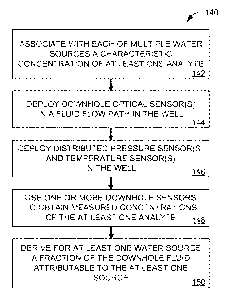
[0049] Fig. 6 is a flowchart of a method 140 for determining sources of water
in a downhole
fluid (e.g., the produced fluid 28 of Fig. 1). During a first block 142 of the
method 140, a
characteristic concentration of at least one analyte is associated with each
of multiple sources
of water. For example, characteristic concentrations of multiple analytes may
be associated
with each of multiple sources of water during the block 142. One or more
downhole optical
sensors (e.g., the optical sensor 40 of Fig. 1 or Figs. 3-4, or the optical
sensors 120 of Figs.
5A-5C) are deployed in a fluid flow path (e.g., the produced fluid 28 of Fig.
1) in the well
during a block 144. Concurrently or separately, a distributed temperature
sensor and/or a
distributed pressure sensor may be deployed in the well during block 144
during a block 146.
During a block 148, measured concentrations of the at least one analyte are
obtained (e.g.,
via the downhole optical sensors). A fraction of the downhole fluid
attributable to the at least
one source is derived for at least one source of water during a block 150.
[0050] Numerous modifications, equivalents, and alternatives will become
apparent to those
skilled in the art once the above disclosure is fully appreciated. It is
intended that the
following claims be interpreted (where applicable) to embrace all such
modifications,
equivalents, and alternatives.
-14-