Note: Descriptions are shown in the official language in which they were submitted.
HEAT EXCHANGER WITH INTEGRATED THERMAL BYPASS VALVE
Cross-reference to related application
This application claims the benefit of and priority to US Provisional patent
application No. 61/579,313, filed December 22, 2011.
Field of the Invention
[0001] The specification relates to a heat exchanger apparatus having
an
integrated thermal bypass valve (TBV).
Background of the Invention
[0002] Heat exchanger systems that vary the path of fluid flowing
through the
heat exchanger in response to a change in the characteristics (e.g.
temperature,
pressure, etc.) of the fluid are known. For example, WO 94/29659 shows a plate-
type oil cooler which has a pressure-responsive valve assembly connected to
the
inlet of the oil-side to permit the oil to bypass the oil-side of the cooler
when the
pressure on the oil-side of the cooler exceeds a predetermined value.
Alternatively,
U.S. Pat. No. 4,669,532 discloses a bimetallic valve which is disposed in the
oil-side
of an oil-cooler to permit the oil to bypass the oil-side of the cooler when
the
temperature of the oil is below a predetermined value.
[0003] Additionally, there are numerous examples of heat exchanger
systems
wherein the flow rate of a fluid flowing through a heat exchanger is
controlled
.. according to the temperature of that of another fluid flowing through the
heat
exchanger. For example, German Laid-Open Application No. 196 37 818 and
European Laid-Open Application No. 787 929 show two such systems wherein the
flow of coolant through an oil cooler is controlled in response to the
temperature of
the oil flowing through the heat exchanger. In both of the systems, a
thermostat is
located upstream of the inlet to measure the oil temperature before the oil
enters
the heat exchanger, although it is also known
1
CA 2859434 2019-06-12
CA 02859434 2014-06-16
WO 2013/091108
PCT/CA2012/050930
to control the flow of coolant through the heat exchanger system in response
to
the oil temperature as it exits the heat exchanger.
[0004] The problem with these systems is that they may take up
considerable amounts of space, which is always at a premium in automotive
applications, a primary use of this art. Additionally, these systems may add
weight to the vehicle to which they are attached, possibly degrading fuel
economy thereby. Furthermore, the environment surrounding the thermostat in
these systems may affect the oil temperature reading, causing more or less
coolant to be directed to the heat exchanger than is actually necessary.
1.0 Summary of the Invention
[0005] According to one aspect of the present application, there is
provided
a heat exchanger apparatus containing:
a heat exchanger, containing
a plurality of plates defining a first fluid channel, a second fluid
channel and a bypass channel;
first fluid inlet and outlet manifolds having first fluid inlet and
outlet, respectively, the first fluid inlet and outlet manifolds being in
fluid communication with the first fluid channel; and, the first fluid
inlet manifold also being in fluid communication with the bypass
channel; and
a thermal bypass valve positioned in the first fluid inlet manifold, the
thermal bypass valve containing:
a sleeve having a first slot and a second slot, the first slot
permitting fluid flow from the first fluid inlet to the bypass channel,
and the second slot permitting fluid flow from the first fluid inlet to
the first fluid inlet manifold;
a drum positioned within the sleeve and slidably movable from a
first position to a second position, the drum having a first aperture
2
CA 02859434 2014-06-16
WO 2013/091108
PCT/CA2012/050930
and one or more additional apertures, the first aperture in fluid
communication with the first fluid inlet and the one or more
additional apertures directing fluid to the first slot or the second slot
in the first or second position; and
a thermal actuator engaging the drum and actuating the drum to
move from the first position to the second position in response to
the temperature of the first fluid.
[0006] According to another aspect of the present application, there is
provided a thermal bypass valve containing:
a sleeve having a first slot and a second slot;
a drum positioned within the sleeve and slidably movable from a first
position to a second position, the drum having a first aperture and one or
more
additional apertures, the first aperture in fluid communication with a first
fluid
inlet and the one or more additional apertures directing fluid to the first
slot or
the second slot in the first or second position; and
a thermal actuator engaging the drum and actuating the drum to move
from the first position to the second position in response to the temperature
of a
first fluid.
Brief Description of the Drawings
[0007] Figure 1 shows a cross-section of a portion of an oil-to-water (OTW)
heater with an internally mounted thermal bypass valve (TBV) in the hot (i.e.,
oil
hotter than the valve actuation set point temperature) condition, with oil
flowing
through the bypass channel;
[0008] Figure 2 shows the OTW heater of Fig. 1 in the cold (oil colder
than
valve set point temperature) condition, with oil flowing through the heat
exchanger;
3
CA 02859434 2014-06-16
WO 2013/091108
PCT/CA2012/050930
[0009] Figure 3 shows a cross-section of a portion of an OTW cooler
with
an internally mounted TBV in the hot condition, with oil flowing through the
heat
exchanger;
[00010] Figure 4 shows the OTW cooler of Fig. 3 in the cold condition,
with
oil flowing through the bypass channel; and
[00011] Figure 5 shows a plan view of a thermal bypass valve in
accordance
with one embodiment, for use in a OTW cooler, with the drum in the first
position.
[00012] Figure 6 shows a thermal bypass valve in accordance with an
embodiment, for use in a OTW cooler, with the drum in the first position.
[00013] Figure 7 shows the sleeve and drum of a thermal bypass valve in
accordance with an embodiment shown in Figure 6.
Description
[00014] The present description discloses, as an embodiment, a heat
exchanger apparatus having a heat exchanger and a thermally actuated bypass
valve positioned within the heat exchanger.
[00015] An oil-to-water (OTW) heat exchanger, where a water-based heat
exchange fluid such as engine coolant, is used to heat or cool oil. When
combined with a suitable valve as disclosed herein, an OTW heat exchanger can
be used either as an oil cooler, or oil warmer. In an OTW cooler
configuration,
where heat is transferred from the oil to the coolant, the oil flows through
the
heat exchanger in the hot state and bypasses the heat exchanger in the cold
state. In an OTW heater configuration, where heat is transferred from the
coolant to the oil, the oil flows through the heat exchanger in the cold state
and
bypasses the heat exchanger in the hot state. An OTW heater can help to
accomplish rapid warm-up of the oil from a cold start condition, knowing that
the
engine coolant heats up more quickly than the oil.
[00016] In accordance with the embodiment of the present specification,
the
thermally actuated bypass valve (TBV) is internally mounted within the heat
4
CA 02859434 2014-06-16
WO 2013/091108
PCT/CA2012/050930
exchanger, and which can help to reduce the overall amount of space required
by the heat exchanger apparatus. In a further embodiment in accordance with
the specification, the heat exchanger apparatus includes a TBV mounted in an
oil
inlet fitting and/or oil inlet manifold of the heat exchanger.
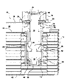
[00017] The embodiments in accordance with the specification will now be
described with reference to the figures. Figures 1 and 2 show a cross-section
of
a portion of an OTW heater 10 containing a core 12 made up of a plurality of
dished heat exchanger plates. The type of plates used is not particularly
limited
and provide for a first fluid channel, a second fluid channel and a bypass
channel
3.0 38. For instance, and as disclosed in the embodiments in Figures 1 to
4, the
first and second fluid channels are formed by a plurality of nested dish
plates,
which in one embodiment can be identical. The first fluid channel, as
disclosed
herein, can provide a passage for flow of oil, while the second fluid channel
can
provide a passage for flow of a coolant or other liquid, for heat exchange.
The
bypass channel 38, as disclosed herein, can be formed by a generally flat
plate
40 positioned above the nested dish plates and a bypass channel cover plate
18.
The bottom of the heater 10 can be provided with another nested flat bottom
dish plate 42 to enclose the heater 10.
[00018] In one embodiment, the heater 10 can be provided with inlet and
outlet manifolds for both the coolant and oil, but only the oil inlet manifold
14 is
shown in the drawings herein. The oil inlet manifold 14 and oil outlet
manifold
are in fluid communication with oil flow passages in core 12 for flow of the
first
fluid. While the coolant inlet manifold and coolant outlet manifold (not
shown)
are fluid communication with the second channel, permitting flow of the
coolant.
In the embodiment disclosed, the manifold 14 is closed at its bottom and
receives oil through its upper end from an oil inlet 44, to which can be
coupled
an oil inlet fitting 16. The fitting 16 is attached to the top of a bypass
channel
cover plate 18, and is provided with an opening for the oil entry. As
disclosed
herein, in one embodiment, the bypass cover plate 18 may cover the entire top
of the core 12.
[00019] In the embodiment disclosed, the bypass channel 38 is present
above the dished heat exchanger plates and close to the oil inlet fitting 16.
5
CA 02859434 2014-06-16
WO 2013/091108
PCT/CA2012/050930
However, the bypass channel 38 could also be positioned, for example and
without limitation, below the core 12 of the heat exchanger plates with the
fitting 16 attached to a top plate of the dished heat exchanger plates.
[00020] Received inside the oil inlet fitting 16 and the oil inlet
manifold 14 is
a thermal bypass valve (TBV) 19 having an outer sleeve 20, generally in the
form of a cylinder. The outer sleeve 20 is closed at its bottom end 46, which
is
further away from the oil inlet 44 or can be open and provided with a flange
extension for retaining a biasing means, as explained further herein and as
shown in the figures. In one embodiment and as disclosed in the figures, a
3.0 major portion of the thermal bypass valve is retained in position
within the oil
inlet manifold 14. In a further embodiment, the top of sleeve 20 has a lip 22
which is retained between the fitting 16 and cover plate 18, for affixing the
sleeve 20 and the TBV 19 in place in the oil inlet manifold 14. The outer
sleeve
20 is provided with upper slots 24 (or first slot) (encircled in Figures 1-4
and 7)
and lower slots 26 (or second slot) (encircled in Figures 1-4, 6 and 7) for
reasons which will become apparent below. The slotted outer sleeve 20 is more
clearly shown in Figures 5-7.
[00021] In the embodiment disclosed in the figures, the upper slots 24
of
the sleeve permits fluid flow from the oil inlet 44 to the bypass channel 38.
While the lower slots 26 in the sleeve permit fluid flow from the oil inlet 44
to
the oil inlet manifold 14, and from there, entering the core 12 of the dished
heat
exchanger plates for heat exchange.
[00022] Located inside the outer sleeve 20 is a drum 28 that can
slidably
move within the sleeve 20 from a first position (Figures 2 and 4) to a second
position (Figures 1 and 3). The drum 28 has a first aperture 48 (encircled in
Figures 1-3) that is in fluid communication with the first fluid inlet 44
(encircled
in Figures 1-3) or opening in the oil inlet fitting 16 to allow the fluid,
such as oil,
to enter the drum. In addition, the drum 28 is also provided with one or more
apertures 36 (encircled in Figures 1-4 and 7), such as a second aperture 52 or
a
second 52 and third 54 aperture, for reasons which will become apparent below.
The drum 28 is also shown in Figures 5 and 6 positioned within the sleeve,
while
Figure 7 shows the drum 28 removed from the sleeve 20. The shape of the
6
CA 02859434 2014-06-16
WO 2013/091108
PCT/CA2012/050930
drum 28 is not particularly limited, and in one embodiment, is generally in
the
form of a cylinder with a closed bottom, which is away from the oil inlet. In
another embodiment, and as shown in the figures, the lower or bottom portion
50 of the drum 28 can have a particular profile, such as an arcuate profile,
as
described further herein.
[00023] The drum 28 contains a thermal actuator 30 which may be in the
form of a wax motor, and which, in one embodiment, is rigidly mounted at its
upper end to the oil inlet fitting 16. The interior of the actuator 30
contains a
wax which expands when heated, such as for example, because of the
temperature of the fluid. The actuator 30 includes a piston 32 which extends
when the wax is heated and can retract when the wax cools. Therefore the
piston 32 is in the extended state in Figure 1 when the oil is hot and is in
the
retracted state in Figure 2 when the oil is cold.
[00024] The piston 32 engages the drum 28 such that the drum 28 moves
downwardly from a first position (as shown in Figures 2 and 4) to a second
position (as shown in Figures 1 and 3) when the piston 32 extends. In the
embodiment disclosed, the shape of the bottom of the drum 28 allows it to be
operatively coupled to the piston 32 with the drum 28, such that the drum 28
moves in response to the piston 32. In the embodiment disclosed in the
figures,
the arcuate profile of the bottom of the drum 28 allows the piston 32 engage
the
drum 28, to operatively couple the piston 32 to the drum 28.
[00025] In a further embodiment and as disclosed herein and shown in
Figures 1 to 4, a biasing means can be provided for biasing the drum 28
towards
the first position. For example, a coil spring 34 between the outer sleeve 20
and
the drum 28 pushes the drum 28 upwardly when the piston 32 retracts.
[00026] As noted above, the drum 28 is also provided with one or more
apertures 36 in addition to the first aperture 48, which is in fluid
communication
with the inlet 44. In one embodiment, as shown in figures 1 and 2, the drum 28
can be provided with second 52 and third 54 apertures (encircled); while in
another embodiment, as shown in Figures 3, 4, 5 and 7, the drum can be
provided with a second 52 aperture (encircled) only. The second 52 and third
54
7
CA 02859434 2014-06-16
WO 2013/091108
PCT/CA2012/050930
apertures (when present) can be provided as a single opening or as multiple
openings. Further, as shown in the figures, the second 52 and third 54
apertures can be longitudinally aligned with each other along the length of
the
drum 28. In an alternative embodiment, the second 52 and third 54 apertures
can be offset (not shown) from each other along the length of the drum 28, so
long as they allow fluid communication from the drum 28 to the slots of the
outer sleeve 20 in different position of the drum, as disclosed herein.
[00027] In one embodiment of a OTW heater where the drum 28 is provided
with a second 52 and third 54 apertures, with the oil in the cold condition,
as
shown in Figure 2, the piston is retracted and the drum 28 is raised, so that
the
drum 28 blocks the upper slots 24 in the outer sleeve 20, and the second
aperture 52 in the drum 28 align with the lower slots 26 of the outer sleeve
20.
Therefore, a closed flow path is created to block off bypass passage 38 from
the
oil inlet fitting 16 to core 12, and the oil enters the oil inlet manifold 14
through
aligned second aperture 52 and slots 26. Therefore the oil enters the manifold
14 and flows through the heat exchanger core 12, where it is heated by the
coolant.
[00028] As the oil temperature increases, the temperature of the
actuator
30 increases and the piston 32 extends to the position shown in Figure 1. This
pushes the drum 28 down so that the second aperture 52 of the drum 28 is
blocked by the outer sleeve 20, and the top of the drum 28 no longer blocks
the
upper slots 24 in the outer sleeve 20. Therefore, in this position, the third
aperture 54 aligns with the first slot 24 in the outer sleeve 20 and the hot
oil
enters the bypass channel 38 between the cover plate 18 and core 12, and does
not enter the inlet manifold 14 of heat exchanger 10.
[00029] Figures 3 and 4 show, as an embodiment, a cross-out section of
a
portion of an OTW cooler 10 which has most of the same elements as OTW
heater 10 described above. Like elements of cooler 10 are therefore described
by like reference numerals. One difference in such an embodiment is that the
drum 28 can be provided with only the first 48 and second 52 (encircled in
Figures 3 and 4) apertures, with the first aperture 48 in fluid communication
8
CA 02859434 2014-06-16
WO 2013/091108
PCT/CA2012/050930
with the oil inlet 44 or opening in the oil inlet fitting 16 to allow oil to
enter the
drum 28.
[00030] In the hot condition shown in Figure 3, with the piston 32
extended,
the second aperture 52 of drum 28 is aligned with the lower slots 26 of outer
sleeve 20, and the drum 28 blocks the upper slots 24. Therefore, the hot oil
flows from inlet 44 to manifold 14, and then flows through core 12 where it
transfers heat to the relatively cool coolant.
[00031] In the cold condition shown in Figure 4, with the piston 32 is
in the
retracted position, the second aperture 52 of the drum 28 align with the upper
slots 24 of the outer sleeve 20 to allow the oil to bypass the heat exchanger
core
12. The drum 28 blocks oil flow to manifold 14, and therefore oil is prevented
from flowing through the lower slots 26 of outer sleeve 20 and into manifold
14.
[00032] While the present invention has been described with reference to
example embodiments and the accompanying drawings, it will be understood by
those skilled in the art that the invention is not limited to the preferred
embodiment and that various modifications could be made thereto without
departing from the scope of the invention as defined by the claims.
9
CA 02859434 2014-06-16
WO 2013/091108
PCT/CA2012/050930
Table of reference numerals
heater 44 oil inlet
12 core 46 bottom end of sleeve
14 oil inlet manifold 48 first aperture
5 16 oil inlet fitting 50 bottom portion
of drum
18 bypass channel cover plate 52 second aperture
19 thermal bypass valve (TBV) 54 third aperture
outer sleeve
22 lip
10 24 upper slots
26 lower slots
28 drum
thermal actuator
32 piston
15 34 coil spring
36 one or more apertures
38 bypass channel
flat plate
42 bottom dish plate
10