Note: Descriptions are shown in the official language in which they were submitted.
CA 02859541 2014-06-16
WO 2013/122659
PCT/US2012/067176
SHEAR WAVE SOURCE FOR VSP AND SURFACE SEISMIC EXPLORATION
RELATED APPLICATIONS
This application claims priority to Provisional U.S. Application Ser. No.
61/598,674,
titled "Shear Wave Source for VSP and Surface Seismic Exploration" and filed
February 14,
2012 by M. E. Willis, which is hereby incorporated herein by reference.
BACKGROUND
Seismology is used for exploration, archaeological studies, and engineering
projects
that require geological information. Exploration seismology provides data
that, when used in
conjunction with other available geophysical, borehole, and geological data,
provides infor-
mation about the structure and distribution of rock types and their contents.
Such information
greatly aids searches for water, geothermal reservoirs, and mineral deposits
such as hydrocar-
bons and ores. Most oil companies rely on exploration seismology to select
sites in which to
drill exploratory oil wells.
Traditional seismology employs artificially-generated seismic waves to map
subsur-
face structures. The seismic waves propagate from a seismic energy source down
into the
earth and reflect from boundaries between subsurface structures. Surface
receivers detect and
record reflected seismic waves for later analysis.
The seismic waves are usually generated by energizing the earth with a
suitable
source of seismic wave energy. Most commonly, the seismic energy sources
create elastic
waves involving earth particle movement in the direction of wave propagation.
These waves,
referred to as compressional or longitudinal waves, are readily generated by
delivering a ver-
tical impact against the earth's surface with an explosion or a mechanical
transducer. The
technical literature has expressed the utility for seismic prospecting
employing a second form
of wave, termed shear waves, wherein the earth particle motion is orthogonal
to the direction
of wave propagation. Shear waves have slower rates of propagation through the
earth than do
longitudinal waves so they can produce a higher degree of resolution at a
given frequency.
This may enable the detection of subterranean anomalies that might otherwise
be undetecta-
ble and the mapping of larger bodies with a higher degree of precision.
Horizontally polar-
ized shear waves are also less likely to be converted into different wave
types upon interact-
1
CA 02859541 2014-06-16
WO 2013/122659
PCT/US2012/067176
ing with horizontal interfaces as is the case with compression waves and
accordingly seismo-
grams made from such waves may be simpler to interpret.
Despite these recognized advantages, the use of shear waves in seismic
prospecting
has been greatly limited because of the unavailability of suitable shear wave
energy sources.
The difficulty encountered in designing such energy sources involves the
manner of coupling
an impact to the earth so that it will impart the desired shear motion to the
earth's surface.
Thus far, shear wave energy sources have proven to be infeasible or lacking in
sufficient re-
producibility, frequency band width, and power for repeated high resolution
surveys for, e.g.,
reservoir monitoring.
BRIEF DESCRIPTION OF THE DRAWINGS
Accordingly, there are disclosed in the drawings and the following description
specif-
ic embodiments of a shear wave source having improved feasibility and
repeatability. In the
drawings:
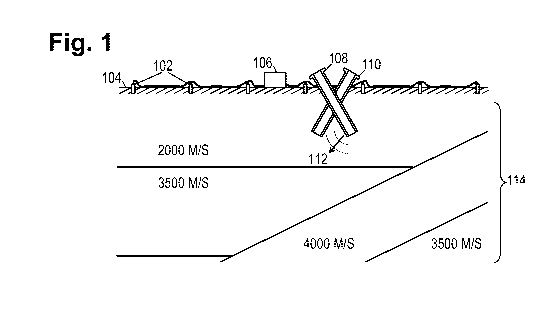
Fig. 1 shows an illustrative seismic survey environment;
Figs. 2a-2b show illustrative seismic source geometries;
Fig. 2c shows an illustrative broomstick charge configuration;
Fig. 2d shows an illustrative seismic survey environment used during hydraulic
frac-
turing operations.
Fig. 2e shows signal graphs of seismic data acquired and processed by an
illustrative
seismic survey recording system during hydraulic fracturing operations.
Fig. 3 shows an illustrative seismic survey recording system;
Fig. 4 shows illustrative seismic traces;
Fig. 5 shows an illustrative data volume in three dimensions;
Fig. 6 shows a flowchart of an illustrative seismic imaging method; and
Fig. 7 shows an illustrative imaging system.
It should be understood, however, that the specific embodiments given in the
draw-
ings and detailed description thereto do not limit the disclosure, but on the
contrary, they pro-
vide the foundation for one of ordinary skill to discern the alternative
forms, equivalents, and
modifications that are encompassed by the scope of the appended claims
DETAILED DESCRIPTION
The disclosed systems and methods are best understood when described in an
illustra-
tive usage context. Accordingly, Fig. 1 shows an illustrative seismic survey
environment in
2
CA 02859541 2014-06-16
WO 2013/122659
PCT/US2012/067176
which surveyors position an array of seismic receivers 102 in a spaced-apart
arrangement on
the earth's surface 104 to detect seismic waves. The array typically extends
for a couple of
kilometers in each direction, and may be moved after each series of shots
until the whole sur-
vey region has been covered. As used herein, the term "shot" refers to a pulse
of seismic
wave energy generated by a seismic energy source at a given time and location.
When the
seismic energy source employs explosive charges, each shot may be the result
of a single det-
onation or the result of a timed sequence of multiple detonations designed to
create a shaped
wave field.
The receivers 102 communicate wirelessly or via cable to a data acquisition
unit 106
that receives, processes, and stores the seismic signal data collected by the
receivers. The
surveyors trigger seismic energy sources 108, 110 at multiple orientations and
optionally at
multiple positions ("shot locations") to generate compressional and shear
waves 112 that
propagate through the earth 114. Such waves reflect from acoustic impedance
discontinuities
to reach the receivers 102. Illustrative discontinuities include faults,
boundaries between for-
mation beds, and boundaries between formation fluids. (Fig. 1 shows three
relatively flat
formation layers and two dipping formation layers of varying composition and
hence varying
speeds of sound, causing acoustic impedance changes at the boundaries.) The
discontinuities
appear as bright spots in the subsurface structure representation that is
derived from the seis-
mic signal data.
The seismic energy sources 108, 110 shown in Fig. 1 are unique in that they
are posi-
tioned within angled, cased boreholes. The boreholes for the sources may be of
any depth, but
it is contemplated that they would not usually exceed 100 feet in depth.
Though the boreholes
are shown as being straight, they may be curved, e.g., being vertical at the
surface and being
at the desired inclination angle at depth. As any shear waves that are
generated are not ex-
pected to propagate significantly along the borehole axis, the well is sloped
to promote prop-
agation of the shear waves downward into the earth. An explosive charge
operating as the
seismic energy source may be detonated near the bottom of the borehole to
generate com-
pressional and shear waves. To enhance the generation of shear waves, the
explosive charge
may be configured to generate a progressive or staged detonation along the
borehole axis.
One configuration for providing such a detonation is shown in Fig. 2c.
Fig. 2c shows a "broomstick distributed charge" seismic energy source created
by
wrapping primacord (or HMX) 122 around a wooden rod 120. Since primacord
detonates at
specific velocity, wrapping the primacord helically around a notched rod will
control the
speed at which the detonation progresses along the borehole axis, thereby
imparting the de-
3
CA 02859541 2014-06-16
WO 2013/122659
PCT/US2012/067176
sired directional aspect to the detonation. The velocity of the detonation
will be controlled by
the "pitch" of the windings of the primacord around the rod. A slower
detonation velocity
will likely impart more directly induced shear wave energy. But in any case,
due to the tilted
inclination of the seismic energy source in the borehole, and the physical
length of the rod
Other directional sources are known and can also be employed. One alternative
con-
figuration employs a series of small explosive charges detonated by a timing
device or other
To improve coupling of the explosive energy from the borehole into the
formation,
the borehole may be filled with a fluid, e.g., water.
Because the borehole is cased, it is expected that it will be re-usable. When
the survey
It is noted that two inclined boreholes are shown in Fig. 1. To enable
separation of the
shear wave information from the compressional wave information, two boreholes
are provid-
ed at similar inclination angles, but 1800 apart from each other as indicated
in Fig. 2a. If the
borehole bottoms are near enough, the signals acquired in response to each
firing can be
30 surveys.
To locate the borehole bottoms in close proximity, the well heads may be
located at
some distance from each other. The actual locations may involve some tradeoffs
with respect
to source proximity and restrictions on surface drilling locations.
Fig. 2b shows boreholes 108 and 110 interspersed with a second pair of
boreholes
4
CA 02859541 2014-06-16
WO 2013/122659
PCT/US2012/067176
109, 111. As the second pair of boreholes is oriented orthogonal to the first
pair, it offers a
shear wave polarization orthogonal to that of the first pair. As before, the
borehole bottoms
are preferably located in fairly close proximity.
The disclosed shear wave source configurations enable the generation of
repeatable,
broad bandwidth shear waves so that surveyors can, for example, perform 9
component VSP
surveys, as well as specifically monitor hydraulic fracture operations. Shear
waves are sensi-
tive to fluid and gas in the fractures. Published studies by Chevron in 1992
and 1994 specifi-
cally show that shear waves are diffracted or reflected off of the induced
hydraulic fractures
for a short time period after the hydraulic fracturing pumps are shut off.
More specifically,
io the studies showed that these shear waves disappear within about 2 hours
after the pumps are
shut off. So with these boreholes in place and the sources ready to go, the
engineers can actu-
ally monitor the fluid filled fracture while it is open and characterize the
success of the frac-
ture treatment in a fashion that is complementary to microseismic monitoring.
See, e.g.,
Meadows and Winterstein, Seismic detection of a hydraulic fracture from shear-
wave VSP
data at Lost Hills Fields, California, Geophysics, Vol. 59, No. 1, January
1994 at 11-26.
To summarize, two or four shallow boreholes can be drilled very closely
together at
inclined directions, preferably about 45 degrees from the vertical. (Angles as
small as 15 de-
grees may suffice.) Each pair of wells is drilled 180 degrees from each other
in map view.
For example one is drilled in the East direction at 45 degrees inclination
from the vertical,
zo while the other one is drilled in the West direction at 45 degrees from
vertical. Each of the
shallow boreholes is optionally lined with PVC or metal casing. (This may not
be necessary
in hard-rock country.) A directional explosive source (e.g., the broomstick
charge of Fig. 2c)
is placed in each borehole, and each is detonated separately, with the
response of the receiver
array to each detonation being acquired and recorded. Combining the recordings
of array re-
sponse signals for sources directionally detonated at orientations 180 degrees
from each other
in map view by summing the signals will enhance the (compressional) P-wave
energy and re-
duce the shear wave energy. Combining the acquired array response signal
recordings made
from these same directional detonations by differencing them will enhance the
shear wave
energy and reduce the P-wave energy. The shear wave source is optionally
detonated again
later in the same cased holes to enable a time lapse recording of changes in
the subsurface.
The results of the above-described combinations and time lapse recordings may
be displayed
as a three-dimensional image, as described below.
Applications include monitoring the effects of hydraulic fracturing on the
properties
of the reservoir, monitoring the effects of thermal heating in the reservoir,
monitoring fluid
5
CA 02859541 2014-06-16
WO 2013/122659
PCT/US2012/067176
drainage in the reservoir, and monitoring secondary recovery efforts by fluid
and gas injec-
tion.
While it should be possible to reload and trigger each borehole fairly quickly
and effi-
ciently (e.g., within 15 minutes), some applications may have speed as a
critical factor. For
such applications, a series of inclined boreholes may be drilled in close
proximity to enable
repeated firings without the waiting time for reloads. Where such speed
requirements do not
exist, the opportunity for repeatable shots with a single pair of boreholes is
expected to be
quite valuable as high-quality time lapse data can be captured very
efficiently.
Fig. 2d shows an illustrative seismic survey recording system used to provide
time-lapse monitoring of hydraulic fracturing operations of a well 132. Pairs
of detonations
are repeatedly triggered within boreholes 108 and 110 at 15 minute intervals,
and the
shear-waves produced by each pair of detonations is detected by receivers 102
within refer-
ence well 134 and measurement well 130. The solid arrow shows the shear-wave
path from
the source and through the fracture zone 136 of well 132 to measurement well
130. The
dashed arrow shows the shear-wave path from the source to reference well 134.
As already
noted, seismic waves generated by a shear-wave source are diffracted and/or
scattered when
passing through a fluid-filled fracture, an effect that is particularly
noticeable during the first
1-2 hours after the hydraulic fracturing pumps have been shut off or shutdown.
Because this
diffraction and/or scattering primarily affects the slow shear-waves, the
shear-wave infor-
m mation acquired by data acquisition unit 106 is further processed to
extract the slow shear-
wave information (e.g., using an Alford rotation to separate fast and slow
shear-wave infor-
mation).
Fig. 2e shows illustrative examples of seismic information acquired by
receiver 102
within reference well 134 of Fig. 2d (graph 202) and by receiver 102 within
measurement
well 130 (graph 204). The slow shear-wave information shown is acquired for
each pair of
detonations triggered and sampled at 15 minutes intervals over a 2 hour period
after the hy-
draulic fracturing pumps are shut off. The illustrative behavior shown is
applicable to a single
stage fracturing, as well as to one or more stages of a multi-stage
fracturing. The graphs iso-
late wavelet arrival times relative to the detonation times between 900 and
1500 milliseconds,
though these times are presented as examples for explanation purposes only.
The slow shear-
wave wavelets of reference well graph 202 display no noticeable variation
between detona-
tions for the time interval shown after the hydraulic fracturing pumps have
been shut off. By
contrast, measurement well graph 204 shows a significant variation in the
amplitude, wave
velocity and wave shape of the wavelets received within the first hour, as
compared to later
6
CA 02859541 2014-06-16
WO 2013/122659
PCT/US2012/067176
received wavelets. In at least some illustrative embodiments, these variations
are further iso-
lated and displayed by subtracting the slow shear-wave information
corresponding to the last
detonation from slow shear-wave information corresponding to each of the
previous detona-
tions. The results of this operation are shown in graph 206 of Fig. 2e. In
other illustrative em-
bodiments, the difference results may be shown as a single wavelet graph that
is presented as
an animated time-lapse sequence. It should be noted that although the above-
described em-
bodiments focus on the period immediately after the hydraulic fracturing pumps
are shut off,
in other illustrative embodiments the shear-wave information may be generated,
received and
processed as described while the pumps are still running, thus tracking any
and all parts of
the fracturing process both before and/or after the pumps are shut off.
It should be noted that although the above-described examples show three wells
and a
single receiver in each of the reference and measurement wells, other numbers
of wells
(fewer or greater) and additional receivers in each well may also be used with
the disclosed
systems and methods. Also, although processing of slow shear waves generated
by the
disclosed systems and methods is described, additional or alternative
processing of the fast
shear waves produced by the disclosed systems and methods is also
contemplated.
Fig. 3 shows an illustrative seismic survey recording system having the
receivers 102
coupled to a bus 302 to communicate digital signals to data recording
circuitry 306. Position
information sensors 304 (and optionally sensors for other parameters) are also
coupled to the
data recording circuitry 306 to enable the data recording circuitry to store
additional infor-
mation useful for interpreting the recorded data. Illustratively, such
additional information
can include the precise locations of the receivers and source firings, source
waveform charac-
teristics, digitization settings, detected faults in the system, etc.
Seismic sensors within receivers 102 may each include multi-axis
accelerometers
and/or geophones and, in some environments, hydrophones, each of which may
take high-
resolution samples (e.g., 16 to 32 bits) at a programmable sampling rate
(e.g., 400 Hz to 1
kHz). Recording circuitry 306 acquires the data streams provided by receivers
102 onto a
nonvolatile storage medium such as a storage array of optical or magnetic
disks. The provid-
ed data is stored in the form of (possibly compressed) sets of seismic traces,
each trace being
the signal detected and sampled by a given receiver in response to a given
shot. (The associ-
ated shot and receiver positions are also stored.) Illustrative seismic
signals are shown in Fig.
4. The signals indicate some measure of seismic wave energy as a function of
time (e.g., dis-
placement, velocity, acceleration, pressure).
The signal data can be partitioned in different ways to make processing and
analysis
7
CA 02859541 2014-06-16
WO 2013/122659
PCT/US2012/067176
more feasible. When partitioned based on a given parameter, each data
partition is called a
"gather". For example, a "shot gather" is the group of traces recorded for a
single firing of the
seismic source. A "common midpoint gather" is the group of traces that have a
midpoint
within a defined region. "Image gathers" are partitions of the migrated
("image") data based
on the given parameter. Thus "common offset image gathers" constitute
partitions of the im-
age data according to the distance between source and receiver, while "common
angle image
gathers" are partitioned according to the incidence (or reflection) angle of
seismic energy at
the image point. At one or more points in the image formation process, the
gathers may be
added together ("stacked") to obtain a combined data set, e.g., a final image
of the subsurface
structure.
A general purpose data processing system 308 receives the acquired seismic
survey
data from the data recording circuitry 306. In some cases the general purpose
data processing
system 308 is physically coupled to the data recording circuitry and provides
a way to con-
figure the recording circuitry and perform preliminary processing in the
field. More typically,
however, the general purpose data processing system is located at a central
computing facility
with adequate computing resources for intensive processing. The survey data
can be trans-
ported to the central facility on physical media or communicated via a
computer network.
Processing system 308 includes a user interface having a graphical display and
a keyboard or
other method of accepting user input, enabling users to view and analyze the
subsurface
structure images derived from the seismic survey data.
The recorded seismic survey data is processed/combined to create a data
volume, i.e.,
a three dimensional array of data values such as that shown in Fig. 5. The
data volume repre-
sents some seismic attribute throughout the survey region. The three-
dimensional array com-
prises uniformly-sized cells, each cell having a data value representing the
seismic attribute
for that cell. Various seismic attributes may be represented, and in some
embodiments, each
cell has multiple data values to represent multiple seismic attributes.
Examples of suitable
seismic attributes include reflectivity, acoustic impedance, acoustic
velocity, and density. The
volumetric data format readily lends itself to computational analysis and
visual rendering,
and for this reason, the data volume may be termed a "three-dimensional
subsurface image"
or "three-dimensional subsurface log" of the survey region. Such an image or
log allows finer
structures to be presented to the user with less distortion than, for example,
a side-by-side
plot of the recorded waveforms.
An illustrative seismic data processing method is shown in Fig. 6. It begins
in block
702 with the obtaining of seismic survey data. The survey data is typically in
a trace format,
8
CA 02859541 2014-06-16
WO 2013/122659
PCT/US2012/067176
e.g., wave field data as a function of shot location, receiver location, and
time, P(rs,rR,t), de-
rived from combining the array response signals from the directional
detonations. Tradition-
ally a change of variable is performed to place this data in the midpoint-
offset-time domain,
i.e., P(m,h,t), where midpoint m=(rs+rR)/2 and offset h=irs-rRI/2. Observing
that this data
represents the wave field observed at the surface (z=0), the wavefield
equation is employed to
extrapolate the subsurface wavefield, a process known as migrating the data.
The fundamen-
tals for this process are described in Chapter 1 of Jon F. Claerbout, Imaging
the Earth's Inte-
rior, Blackwell Scientific Publications, Oxford, 1985.
Among other things, migration requires a velocity model v(r), which specifies
a wave
propagation speed for every point r in the subsurface volume V. Accordingly,
an initial veloc-
ity model is postulated in block 704. An initial velocity model can be
postulated based on any
one of a number of approaches including: a constant velocity, a velocity that
increases linear-
ly with depth, a velocity derived from theoretical models of rock compaction,
and measured
values from sonic logs of an exploratory borehole.
In block 706, the velocity model is used to migrate the survey data. Any one
of the
existing wave-equation based migration techniques can be employed to obtain
the subsurface
data volume. Various migration techniques can be employed. Such alternative
techniques
may result in different image gathers, e.g., shot index gathers as described
in Xie, X., and H.
Yang, 2008, The finite-frequency sensitivity kernel for migration residual
moveout: Geo-
physics, 73, S241-249.
In block 708, the gathers are stacked to obtain a combined image of the
structure in
the subsurface volume. Even though the velocity model may be in error, one can
usually per-
ceive significant structure in the stacked image data. The individual gathers
and stacked im-
age data can be processed to derive depth residuals or other measures of the
velocity model
error. Based on such errors, the velocity model is updated in block 722. In
block 724, the sys-
tem determines whether the velocity model is satisfactory. One possible test
is whether con-
vergence has been achieved, i.e., whether the velocity updates are below some
predetermined
threshold. Another possible test is whether the residual moveout has been
largely eliminated
from the image gathers or whether the stacked image data appears reasonably
clear and free
of ghosting or smearing. If the velocity model is not satisfactory, the blocks
706-724 are re-
peated until the velocity model is deemed satisfactory. The system displays
the final subsur-
face log or image to a user in block 726.
It is contemplated that the operations shown in Fig. 6 may be implemented in
the form
of software, which can be stored in computer memory, in long-term storage
media, and in
9
CA 02859541 2014-06-16
WO 2013/122659
PCT/US2012/067176
portable information storage media. It should be noted that illustrative
method of Fig. 6 is
provided as an explanatory aid. In practice, the various operations shown in
Fig. 6 may be
performed in different orders and need not even be sequential. Seismic data
processing can
benefit substantially from parallelism. In some processing method embodiments,
data from
different survey regions may be processed independently. In other embodiments,
the opera-
tions may be "pipelined" or otherwise performed concurrently. Additional
operations may be
added to the illustrative method and/or several of the operations shown may be
omitted.
Fig. 7 shows an illustrative computer system 900 for performing seismic data
pro-
cessing including seismic imaging using shear wave survey information. A
personal work-
station 902 is coupled via a local area network (LAN) 904 to one or more multi-
processor
computers 906, which are in turn coupled via the LAN to one or more shared
storage units
908. LAN 904 provides high-speed communication between multi-processor
computers 906
and with personal workstation 902. The LAN 904 may take the form of an
Ethernet network.
Personal workstation 902 serves as a user interface to the processing system,
enabling
a user to load survey data into the system, to retrieve and view image data
from the system,
and to configure and monitor the operation of the processing system. Personal
workstation
902 may take the form of a desktop computer with a graphical display that
graphically shows
survey data and 3D images of the survey region, and with a keyboard that
enables the user to
move files and execute processing software.
Multi-processor computer(s) 906 provide parallel processing capability to
enable suit-
ably prompt conversion of seismic trace signals into a survey region image.
Each computer
906 includes multiple processors 912, distributed memory 914, an internal bus
916, and a
LAN interface 920. Each processor 912 operates on an allocated portion of the
input data to
produce a partial image of the seismic survey region. Associated with each
processor 912 is a
distributed memory module 914 that stores conversion software and a working
data set for
the processor's use. Internal bus 916 provides inter-processor communication
and communi-
cation to the LAN networks via interface 920. Communication between processors
in differ-
ent computers 906 can be provided by LAN 904.
Shared storage units 908 may be large, stand-alone information storage units
that em-
ploy magnetic disk media for nonvolatile data storage. To improve data access
speed and re-
liability, the shared storage units 908 may be configured as a redundant disk
array. Shared
storage units 908 initially store an initial velocity data volume and shot
gathers from a seis-
mic survey. The (iteratively-updated) common angle image gathers can be
temporarily stored
on shared storage units 908 for later processing. In response to a request
from the workstation
CA 02859541 2014-06-16
WO 2013/122659
PCT/US2012/067176
902, the image volume data can be retrieved by computers 906 and supplied to
workstation
for conversion to a graphical image to be displayed to a user.
Numerous variations and modifications will become apparent to those skilled in
the
art once the above disclosure is fully appreciated. For example, the inclined
boreholes may be
drilled as oppositely-directed laterals from a common vertical shaft. Also,
although the time
lapse sequence of the example presented was produced from shear wave
information acquired
from shots triggered and sampled at 15 minute intervals over a period of 2
hours after pump
shutdown, embodiments that use different intervals and periods are within the
scope of the
present disclosure. In many cases, three-dimensional image logs may be
replaced by two-
dimensional image logs. It is intended that the following claims be
interpreted to embrace all
such variations and modifications.
11