Note: Descriptions are shown in the official language in which they were submitted.
CA 02860035 2014-06-20
WO 2013/090994 PCT/AU2012/001554
GROUND ENGAGING TOOLS
This invention relates to ground engaging tools for carthmoving and mining
equipment. The invention has particular application to ground engaging tools
.for the cutting
edge of excavator buckets and the invention will be described with particular
reference to
5' such application. However, the invention may have application to ground
engaging tools for
other types of equipment, for example, shovel buckets, bucket loaders,
draglind buckets,
- bulldozer blades, drotts, bobcats, and backhoes.
Typically, excavator buckets and the like have a base or floor with a cutting
edge or
lip to which ground engaging tools are fitted to engage the ground or spoil
which is to be
excavated or loaded as the case may be and to protect the lip from wear.
Commonly, the
ground engaging tools have a number of components. The first component, often
called the
nose, nose base, nosepiece or nose mount, is usually fixed in a pennanent or
semi-permanent
manner to the base of the bucket by welding and protrudes forward from the
lip. The second
component is releasably mounted on or to the nose so that it can be replaced
when it reaches
a predetermined wear condition. In some types of equipment the second
component is the
cutting tip, tooth or tooth 'point which engages the ground at its front edge
and suffers the
main wear, while in other equipment, the second component is an adaptor to
which a third
component being the cutting tip Or tooth. is releasably fitted which in turn
suffers the main
wear while the adaptor suffers lesser wear. Thus, it will be understood that
white the tooth in .
a three component system will have a. much shorter life than the adaptor the
adaptors
themselves do eventually wear out and have to be replaced. Even the nose may
wear out, long
before the bucket floor and walls and haye to be replaced but in the case of
the nose, it can be
cut away from the base and replaced by new noses which can be welded to the
base but that
requires substantial downtime for a fairly substantial operation. In the case
of a two
component system, while the releasable tooth can be replaced relatively
easily, if the nose
wears out, a fairly substantial operation is required to replace it as with a
three component
system,
Typically, the nose includes a forwardly extending protuberance which. is
adapted to
engage in a complementary cavity provided in the tooth or the adaptor in a
three component
3P -system. In some prior art systems, the protuberance includes a tapered
portion which is often
referred to as the "cone". In this specification, the Cerra "cone' is also
used to refer to the
tapered portion even though it may not be conical in shape.
In a two component system, the adaptor has a cavity opening at one end in
which the
complementary protuberance on the nose engages and a protuberance at the other
end which
CA 02860035 2014-06-20
WO 2013/090994
PCT/AU2012/001554
2
is adapted to engage in the complementary tooth cavity. The two components are
commonly
relcasably secured together by one or more locking pins which lock the tooth
and the
underlying adaptor together or the adaptor and the underlying nose in the ease
of a three
component system, = There are various securing systems available which are
commonly
referred to as retaining systems.
In one known retainer system, a tapered pin is driven through aligned holes
extending
through the tooth and the adaptor from top to bottom or the adaptor and the
nose. However, =
the hole causes a weakness in the nose or the adaptor in a three component
system which
leads to failure. In another case, two opposed relatively short locking pins
located in the nose
arc arranged to be extended into complementary holes Or openings in the
opposed side walls
of the tooth or adaptor mounted on the nose.
Tt will be appreciated that the cavities and protuberances are shaped to
inhibit relative
movement between the engaging components when in operation, although the
presently.
known systems do not inhibit relative movement as well as desired. Further,
the presently
available retaining systems, do not provide the reliability or efficiency of
operation desired.
In this specification, unless the context clearly requires a different
mooning, the term
forward and its derivatives are to be understood as being in the direction of
movement of the
tooth or bucket when digging or tilling the bucket with spoil. Terms such as
upper, lower,
side, front, rear, and the like are to be understood in the context of the
tooth digging so that
the leading edge of the tooth is the front of the tooth.
With the foregoing in view, the invention resides broadly in a nose mount and
complementary tooth in combination for eartlunoving and mining equipment, the
nose mount
having a base for securing the nose mount to the lip of a bucket and a
protuberance extending
forwardly therefrom,
the protuberance including a cone portion defined at least in part by spaced
apart
upper and lower faces and opposed spaced apart side faces, the upper and lower
faces being
joined = to the side faces by curved corner faces and the opposed upper and
lower faces
converging towards each other and the opposed side CaceS converging towards
each other
away from the base so that the curved corner faces diminish away from the
base,
the upper and lower faces and side faces of the cone portion terminating in a
beak
portion at the front of the protuberance, the beak portion having opposed
spaced apart upper
and lower faces joined by opposed spaced apart side faces, the upper face,
lower face and
side faces of the beak portion being contiguous with the upper face, lower
face and side faces
CA 02860035 2014-06-20
WO 2013/090994
PCT/AU2012/001554
3
of the cone portion respectively, and the upper and lower faces of the beak
portion being
generally parallel arid the side faces of the beak portion also being
generally parallel,
the tooth having a cutting tip at its front and a mounting portion rearward of
the
cutting tip, the mounting portion having a cavity .therein opening to the
rear, and the cavity
including a cone portion extending forward from the rear opening,
the cone portion being defined at least in part by spaced apart upper and
lower faces
and opposed spaced apart side faces, the upper and lower faces being joined to
the side faces
by curved corner faces and the opposed upper and lower faces converging
towards each other
and the opposed side faces converging towards each other away from the rear
opening so that
the curved corner faces diminish away from the rear opening,
the upper and lower faces and the side faces of the cone portion terminating
in a beak
portion at the front of the cavity, the beak portion being defined at least in
part by opposed
spaced apart upper and lower faces joined by opposed spaced apart side faces,
the upper face,
lower face and side faces of the beak portion being contiguous with the upper
face, lower
face and side faces of the cone portion respectively, and the upper and lower
faces of the beak
portion being generally parallel and the side faces of the beak portion also
being generally
parallel and contiguous with a front face of the beak portion,
the nose mount and the tooth being so made and arranged that the beak portion
of the
protuberance substantially engages in the beak portion of the cavity with the
upper and lower
faces and side faces of the beak portion of the protuberance engaging with
tile upper and
lower faces and side faces of the beak portion of the cavity, and the upper
and lower .rtiees
and side faces of the cone portion of the nose mount engaging with the upper
and lower -faces
and side faces of the cone portion of the cavity.
In another aspect, the invention resides broadly in a nose mount and
complementary
adaptor in combination for earthmoving and mining equipment, the nose mount
having a base
for securing the nose mount to the lip of a bucket and a protuberance
extending forwardly
therefrom,
the protuberance including a cone portion defined at least in part by spaced
apart
upper and lower faces and opposed spaced apart side faces, the upper and lower
faces being
joined to the side faces by curved corner faces and the opposed upper and
lower faces
converging towards each other and the opposed side faces converging towards
each other =
away from the base so that the curved corner faces diminish away from the
base,
the upper and lower faces and side faces of the cone portion terminating in a
beak
portion at the ETOIlt of the protuberance, the beak portion having opposed
spaced apart upper
CA 02860035 2014-06-20
WO 2013/090994
PCT/AU2012/001554
4
=
and lower faces joined by opposed spaced apart side faces, the upper face,
lower face and
side faces of the beak portion being contiguous with the upper face, lower
face and side faces
of. the cone portion respectively, and the upper and lower faces of the beak
portion being
generally parallel and the side faces of the beak portion also being generally
parallel,
the adaptor including a mounting portion for mounting the adaptor on the nose
mount
and a nose portion extending forwardly from the mounting portion for mounting
a tooth
thereon,
the mounting portion having a cavity therein opening to the rear, the cavity
including
= a cone portion extending forward from the rear opening,
the cone portion, being defined at least in part by spaced apart upper and
lower faces
and opposed spaced apart side faces, the upper and lower faces being joined to
the side faces
by curved corner faces and the opposed upper and lower faces converging
towards each other
away from the rear opening and the opposed side faces converging towards each
other away
from the rear opening so that the curved corner faces diminish away :from the
rear opening,
the upper and lower faces and the side faces of the cone portion terminating
in a beak
portion at the front of the cavity, the beak portion being defined at least in
part by opposed
spaced apart upper and lower faces joined by opposed spaced apart side faces,
the upper face,
lower face and side faces of the beak portion being contiguous with the upper
face, lower
face and side faces of the cone portion respectively, and the upper and lower
faces of the beak
portion being generally parallel and the side faces of the beak portion also
being generally
parallel and contiguous with a front face of the beak portion,
the nose mount and the adaptor being so made and arranged that .the beak
portion of
the protuberance substantially engages in the beak portion of the cavity with
the upper and
lower faces and side faces of the beak portion of the protuberance engaging
with the upper
and lower faces and side faces of the beak portion of the cavity, and the
upper and lower
faces and side faces of the cone portion of the nose mount engaging with the
upper and lower
faces and side faces of the cone portion of the cavity.
In yet another aspect, the invention resides broadly in a tooth for
earthmoving and
mining equipment, including:
a cutting tip; and
a mounting portion rearward of the cutting tip, the mounting portion having a
cavity
therein opening to the rear and including a cone portion extending forward
from the rear
opening and terminating in a bcakportion,
CA 02860035 2014-06-20
WO 2013/090994.
PCT/AU2012/001554
=
the cone portion being defined at least in part by spaced apart upper and
lower faces
and opposed spaced apart side faces, the upper and lower faces being joined to
the side faces
by curved corner faces and the opposed upper and lower faces converging
towards each other
and the opposed side faces converging towards each other away from the rear
opening so that
5 the curved corner faces diminish away from the rear opening,
the upper and lower faces and the side faces of the cone portion terminating
in a beak
portion at the front. of the cavity, the beak portion being defined at least
in part by opposed
spaced apart upper and lower faces joined by opposed spaced apart side faces,
the upper face,
lower face and side faces of the beak portion being contiguous with the upper
face, lower
face and side faces of the cone portion respectively, and the upper and lower
faces of the beak
portion being generally parallel and the side faces of the beak portion also
being generally
parallel and contiguous with a front face of the beak portion.
In yet another aspect, the invention resides broadly in an adaptor for
earthmoving and
mining equipment, the adaptor including:
a mounting portion for mounting the adaptor on a nose mount connected to the
lip of a
bucket and a protuberance extending forwardly from the mounting portion for
mounting a
tooth thereon,
the mounting portion having a cavity therein opening to the rear and including
a cone
portion extending forward from the rear opening, thc cone portion being
defined at least in
part by spaced apart upper and lower faces and opposed spaced apart side
faces, the upper
and lower faces being joined to the side .faces by curved corner faces and the
opposed upper
and lower faces converging towards each other and the opposed side faces
converging
towards each other away from the rear opening so that the curved corner faces
diminish away
from the rear opening, the upper and lower faces and the side faces of the
cone portion
terminating in a beak portion at the front of the cavity, the beak portion
being defined at least
in part by opposed spaced apart upper and lower faces joined by opposed spaced
apart side
faces, the upper face, lowef face and side faces of the beak portion being
contiguous with the
upper face, lower face and side faces of the cone portion respectively, and
the upper and
lower -faces of the beak portion being generally parallel and the side faces
of the beak portion
also being generally parallel and Contiguous with a front face of the beak
portion, and
the protuberance including a cone portion defined at least in part by spaced
apart
tipper and lower faces and opposed spaced apart side faces, the upper and
lower faces being
joined to the side faces by curved corner faces and the opposed upper and
lower faces
converging towards each other and the opposed side faces 'converging towards
each other
CA 02860035 2014-06-20
WO 2013/090994
PCT/AU2012/001554
6
away from the mounting portion so that the curved corner faces diminish away
from the
mounting portion, the upper and lower faces and side faces of the cone portion
terminating in
a beak portion at the front of the protuberance, the beak portion having
opposed spaced apart
upper and lower faces joined by opposed spaced apart side faces, the upper
face, lower face
and side faces of the beak portion being contiguous with the upper face, lower
face and side
faces of the cone portion respectively, and the upper and lower faces of the
beak portion
being generally parallel and the side faces of the beak portion also being
generally parallel.
In yet another aspect, the invention resides broadly in an adaptor for
earthmoving and
mining equipment, the adaptor including:
a mounting portion for mounting the adaptor on a nose mount connected to the
lip of a
bucket and a protuberance extending forwardly from. the mounting portion for
mounting a
tooth thereon,
the protuberance including a orte portion defined at least in part by spaced
apart
upper and lower faces and opposed spaced apart side faces, the upper and lower
faces being
joined to the side faces by curved corner faces and the opposed upper and
lower faces
converging towards each other and the opposed side faces converging towards
each other
away from the mounting portion so that the curved corner faces diminish away
from the
mounting portion, the upper and lower faces and side faces of the cone portion
terminating in
a beak portion at the front of the protuberance, the beak portion having
opposed spaced apart
upper and lower faces joined by opposed spaced apart side faces, the upper
face, lower face
and side faces of the beak portion being contiguous with the upper face, lower
face and side
faces of the cone portion respectively, and the upper and lower faces of the
beak = portion
= being generally parallel and the side faces of the beak portion also
being generally parallel.
In yet another aspect, the invention resides broadly in an. adaptor for
earthmoving and
mining equipment, the adaptor including:
a mounting portion for mounting the adaptor on a nose mount connected to the
lip of a
bucket and a protuberance extending forwardly from the mounting portion for
mounting a
tooth thereon,
the mounting portion having a cavity therein opening to the rear and including
a one
portion extending forward from the rear opening, the cone portion being
defined at least in
part by spaced apart upper and lower faces. and opposed spaced apart side
faces, the upper
and lower faces being joined to the side faces by curved comer faces and the
opposed upper
and lower faces converging towards each other and the opposed side faces
converging
towards each other away from the rear opening so that the curved corner faces
diminish away
it ,4=1=111I
CA 02860035 2014-06-20
WO 2013/090994 PCT/AU2012/001554
=
7
from the rear opening, the upper and lower faces and the side faces of the
cone portion
terminating in a beak portion at the front of the cavity, the beak portion
being defined at least
in part by opposed spaced apart upper and lower faces joined by opposed spaced
apart side
faces, the upper face, lower face and side faces of the beak portion being
contiguous with the
upper face, lower face and side faces of the cone portion respectively, and
the upper and
lower faces of the beak portion being generally parallel and the side faces of
the beak portion ,
also being generally parallel and contiguous with a front face of the beak
portion.
In yet another aspect, the invention resides broadly in a nose mount for
earthmoving
and mining equipment, including:
.10 a base for mounting the nose mount to the lip of a bucket; and
a protuberance extending forwardly from the base, the protuberance including a
cone
portion defined at least in part by spaced apart upper and lower faces and
opposed spaced
apart side faces, the upper and lower faces being joined to the side faces by
curved corner
faces and the opposed upper and lower faces converging towards each other and
the opposed
side faces converging towards each other away from .the base so that the
curved corner faces
diminish away from the base, =
the upper and lower faces and the side faces of the cone portion terminating
in a beak
portion at the front of the protuberance, the beak portion having opposed
spaced .apart upper
and lower faces joined by opposed spaced apart side faces, the upper face,
lower face and
side faces of the beak portion being contiguous with the upper face, lower
face and side faces
of, the cone portion respectively, and the upper and lower faces of the beak
portion being
generally parallel and the side faces of the beak portion also being generally
parallel and
contiguous with a front face of the beak portion.
Preferably, the protuberance and the cavity are symmetrical about a vertical
plane
extending from the upper face to the lower face (the vertical symmetrical
plane). It is also
preferred that the protuberance and the cavity be symmetrical about a
horizontal plane
extending from the front face of the beak portion to the mounting portion in
the case of an
= adaptor or the base in the case of a nose mount in the central part (the
horizontal symmetrical
plane). It that respect, it will be appreciated that the curved corner faces
joining the upper
face to the side faces and the lower face to the. side faces may have
different radii.
Preferably, the front face of the beak portion of the protuberance and' the
cavity is
generally planar.
Preferably, the upper and lower faces of the cone portion Of the nose and the
cavity
each include a substantially planar centre portion which is contiguous with
the curved corner
CA 02860035 2014-06-20
WO 2013/090994
PCT/AU2012/001554
8
portions on opposite sides thereof. However, in a particularly preferred form,
the
protuberance includes a keying ridge forming opposed keying shoulders with the
lower face
of the cone portion and depending therefrom.
= Preferably, the adaptor and the tooth have an opening in each side of the
mounting
portion thereof for mounting a lock therein for use in releasably securing the
mounting
portion to an adaptor or a nose mount in the case of a tooth or a nose mount
in the case of an
adaptor. In a preferred form, the openings are centred on a transverse axis
passing through a
horizontal plane about which the adaptor and tooth arc each substantially
symmetrical as
previously mentioned.
Preferably, the cone portion of the protuberance of the nose mount and the
adaptor
has an opening in each side thereof for receiving, therein a retaining lug,
pin or the like from a
lock mounted in the mounting portion of an adaptor or tooth for securing an
adaptor to a nose
mount or a tooth to an adaptor as the case may be. In a particularly preferred
form such
openings are blind holes centred on a transverse axis passing through the
horizontal
symmetrical plane and substantially coaxial with the corresponding axis
passing through
aligned complementary holes formed in the tooth or adaptor as the case may be
as previously
described.
Preferably, the base of the nose mount and the mounting portion of the adaptor
include spaced apart recesses (ear pockets) adapted to provide respective load
bearing faces
adjacent the side faces for transferring pushing loads from the nose mount or
the adaptor as
the case may be to the tooth or the adaptor when the adaptor is fitted to a
nose mount. in a
preferred form in which complementary holes are formed in the sides of the
nose mount, such
bearing faces are orthogonal to the vertical symmetrical plane and part
cylindrical in form
and centred on the transverse Centre axis of such complementary holes.
Advantageously,
such car pockets allow the tooth and the adaptor to have complementary
projections or ears to
be provided about the holes in the sides thereof to provide sufficient
strength in that area and
such complementary projections arc arranged to engage the respective load
bearing faces.
Advantageously, it is preferred that the projections be arranged to engage the
side faces of the
cone portion to assist in inhibiting relative movement between the adaptor or
the tooth and
the nose mount or between the tooth and the adaptor.
In yet another aspect the invention resides broadly in a nose mount having a
base for
securing the nose mount to the lip of a bucket and a protuberance extending
forwardly
therefrom,
=
CA 02860035 2014-06-20
WO 2013/090994
PCT/AU2012/001554
=
9
the protuberance including a cone portion defined at least in part by spaced
apart
upper and lower faces and opposed spaced apart side faces, the upper and lower
faces being
joined to the side faces by curved corner faces and the opposed upper and
lower faces
converging towards each other and the opposed side faces converging towards
each other
away from the base so that the curved corner faces diminish away from the
base,
the upper and lower faces and side faces of the cone portion terminating in a
beak
poition at the front of the protuberance, the beak portion having opposed
spaced apart upper
and lower faces joined by 'opposed spaced apart side faces, the upper .face,
lower face and
side faces of the beak portion being contiguous with the upper face, lower
face and side fares
of the cone portion respectively, and the upper and lower faces of the beak
portion being =
parallel and of a predetermined length away from the base and thc side faces
of the beak
portion also being parallel,
and wherein the relative magnitude of at least one geometrical feature is
selected
according to predetermined ratios.
In still yet another aspect, the invention resides broadly in a tooth for
earthmoving and
mining equipment, the tooth having a cutting tip at its front and a mounting
portion rearward
of the cutting tip, the mounting portion having a cavity therein opening to
the rear and
including a cone portion extending forward from the rear opening and
terminating in a beak
portion,
the cone portion being defined at least in part by spaced apart upper and
lower faces
and opposed spaced apart side aces, the upper and lower faces being joined to
the side faces
by curved corner faces and the opposed upper and lower faces converging
towards each other
and the opposed side fades converging towards each other away from the rear
opening so that
the curved corner faces diminish away from the rear opening,
the upper and lower faees and the side faces of the cone portion terminating
in a beak =
portion at the front of the cavity, the beak portion being defined at least in
part by opposed
spaced apart upper and lower faces joined by opposed spaced apart side faces,
the upper face,
lower face and side faces of the beak portion being contiguous with the upper
face, lower
face and side faces of the cone portion respectively,00 and the upper and
lower faces of the
beak ',Onion being parallel and the side faces of the beak portion also being
parallel and
contiguous with a front face of the beak portion,
and wherein the relative magnitude of at least one geometrical feature is
selected
according to one or more predetermined ratios.
CA 02860035 2014-06-20
WO 2013/090994
PCT/AU2012/001554
. In still yet another aspect, the invention resides broadly in an
adaptor for earthmoving
and mining equipment, the adaptor having a mounting portion for mounting the
adaptor on a
nose mount connected to the lip of a bucket and a protuberance extending
forwardly from the
mounting portion for mounting a tooth thereon, the mounting portion having a
cavity therein
5 opening to the rear and including a cone portion extending forward from
the rear opening,
the cone portion being defined at least in part by spaced apart upper and
lower faces
and opposed spaced apart side faces, the upper and lower faces being joined to
the side faces
by curved corner laces and the opposed upper and lower faces converging
towards each other
and the opposed side faces converging towards each other away from the rear
opening so that
10 the curved comer faces diminish away from the rear opening,
the upper and lower faces and the side faces of the cone portion terminating
in a beak
portion at the front of the cavity, the beak portion being defined at least in
part by opposed
spaced apart upper and lower faces joined by opposed spaced apart side faces,
the upper face,
lower face and side faces of the beak portion being contiguous with the upper
face, lower
face and side faces of the cone portion respectively, and the upper and lower
faces of the beak
portion being parallel and the side faces of the beak portion also being
parallel and
contiguous with a front face of the beak portion,
and wherein the relative magnitude of at least one geometrical feature is
selected
according to one or more predetermined ratios.
Preferably, the one or more predetermined ratios are selected from the ratio
of the
width of the nose portion to the height of the nose portion adjacent the base,
the length of the ,
beak portion the length of the cone portion away from the base, the width of
the upper face of
the cone portion to the .width of the cone portion adjacent the base, the
radius of the upper
corner portion adjacent the upper face of the cone portion to the radius of
the upper corner
adjacent the side face, the width of the cone portion adjacent the base to the
radius of the
upper corner portion adjacent the upper face, and the radius of the bottom
corner adjacent the
lower face to the radius of the upper corner portion-of the beak portion.
In order that the invention may be more clearly understood and put into
practice, the
invention will now be described with reference to the accompanying.drawings
wherein:
Fig. 1 is pictorial representation of an excavator bucket from the front with
a plurality
of teeth mounted on complementary nose mounts at the lip of the bucket;
Fig. 2 is pictorial representation of the excavator bucket of Fig. I from its
right side;
Fig. 3 is a front elevation of .the excavator bucket of Fig. 1;
ital-101120 = =
CA 02860035 2014-06-20
WO 2013/090994
PCT/AU2012/001554
ii
Fig. 4 is pictorial representation from above one side of a nose mount
according to the
invention adapted to be welded to the lip portion of an excavator bucket of
the type shown in
Fig. 1;
Fig. 5 is pictorial representation of the nose mount. of Fig. 5 from under one
side;
Fig. 6 is side elevation of the nose mount of Fig. 4;
Fig. 7 is the same side elevation as Fig. 6 with some features remove for
clarity;
Fig. 8 is a. plan of the nose mount of Fig. 4;
Fig. 9 is a sectional plan of the nose mount of Fig. 4 along a symmetrical
horizontal
plane 9 - 9;
Fig. 10 is a front elevation of the nose mount of Fig. 4;
Fig. 11 is a front elevation of the nose mount of Fig. 4 with some lines
removed for
clarity;
Fig. 12 is a sectional side elevation of the nose mount of Fig. 4 along a
vortieal
symmetrical plane containing the longitudinal axis with rounds and fillets
removed for
clarity;
Fig. 13 is a plan of the nose mount of Fig. 4 with rounds and fillets removed
for
clarity; and
Fig. 14 is a sectional plan of the nose mount of Fig. 4 along a Symmetrical
horizontal
plane.
Fig. 15 is a pictorial representation of an adaptor according to the
invention, the
adaptor having the same features as a tooth according to the invention in its
mounting portion
and a cutting lip at the front end;
Fig. 16 is a pictorial representation of the adaptor of Fig. 15 from one side;
Fig. 17 is a pictorial representation of the adaptor of Fig. 15 from the rear;
Fig. 18 is a pictorial representation of an adaptor according to the invention
fitted to a
. nose mount accbrding to the invention and a tooth .according to the
invention fitted to the
adaptor;
Fig. 19 is a rear elevation of the adaptor of Fig. 15;
Fig.. 20 is a pictorial, representation of part of a bucket with nose mounts,
adaptors and
teeth fitted according to the invention;
Fig. 21 is a pictorial sectional elevation along a symmetrical vertical plane
of a nose
mount with an adaptor mounted thereon and a tooth mounted to the adaptor
according to the
invention similar to the arrangement shown in Fig.18; and
CA 02860035 2014-06-20
WO 2013/090994
PCT/AU2012/001554
12
Fig. 22 is a pictorial sectional plan along a symmetrical horiz.ontal plane of
the nose
mount with adaptor mounted thereon and tooth mounted to the adaptor as shown
in Fig 21.
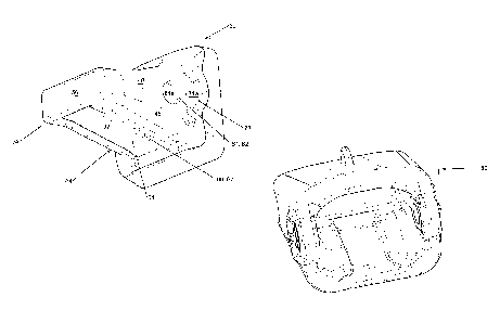
The bucket 10 illustrated in Fig. 1 has a floor 11 with a ground engaging
leading edge
(or lip) 12 at' its front. The floor curves upwardly behind the lip to form a
contiguous rear
wall 13 which in turn curves upwards and forwards to form a contiguous uPper
wall 14, the
floor, the rear wall and thc upper wall forming a generally u-shaped bucket
enclosed by
opposed generally planar side walls 16 and 18 with an open front 15. A curved
lifting arch or
bar 21 extends across the top of the bucket between the side walls and a
plurality of spaced
apart lifting lugs 19 are welded to the arch and the upper wall for connection
of an excavator
lifting arm and crowd arm thereto in known manner.
A plurality of spaced apart nose mounts 30 are welded to the bucket floor 11
across
the front and extend forward from the lip 12. The nose mounts described in
this embodiment
are solid cast iron or steel fittings. Teeth 25 are fitted to the nose mounts
as will be described
in more detail later.
AS can be seen in Figs. 4 to 10, the nose mount 30 is shown cut away at its
rear (the
lip end) along lines A and 13, the portion of the nose mount beyond lines A
and 13 by which it
is mounted to the lip of the bucket not being relevant to the present
invention. It will be
appreciated that the portion by which it is mounted to the floor of the bucket
may have
different shapes and arrangements depending on the bucket floor to which the
nose mount is
to be mounted. In that regard, the present invention relates to the shape of
the portion of the
mount which is referred to herein as base 31 and the protuberance 32 which
extends
therefrom.
The protuberance 32 includes a cone portion 33 extending forward from the base
31
and terminating in a beak portion 34. The cone portion is defined by upper and
lower faces
36 and 37 which converge forwardly away from the base 31 and two opposed side
faces 40
and. 41 which also converge away from the base, the upper and lower -faces
being joined to
the side faces by curved corner thces 42, 43, 44 and 45 which are contiguous
with the upper
and lower faces and the opposed side faces. It will be appreciated that the
converging upper
and lower faces and the converging side faces result in the corner faces
diminishing away
from the base towards the beak portion to a line at the beak portion.
The upper and lower faces of the cone portion converge into the opposed
parallel
upper and lower faces 51 and 52 respectively of the beak portion and the
opposed side faces
and 41 of the cone portion converge into the opposed parallel side faces 53
and 54 of the
beak portion at vertical plane 55. Advantageously, the upper and lower faces
and the two
CA 02860035 2014-06-20
WO 2013/090994
PCT/AU2012/001554
13
opposed side faces of the beak portion terminate in a front face 56 which is
generally planar
and orthogonal to the opposed parallel side faces and the opposed parallel
upper and lower
faces of the beak portion.
It will .be appreciated that the protuberance is substantially symmetrical
about a
substantially "horizontal" plane passing through the centreline of the front
face 56 along line
9 ¨ 9 and the horizontal centreline of the base 31. The term "horizontal" is
used in describing
the general appearance of the nose mount even though that =plane might not be
actually
horizontal in use. it will also be appreciated that the nose mount is
symmetrical about a
vertical plane passing through the vertical centreline of the front face and
the vertical
centreline of the base along line 11 ¨ 11 as can be seen in Fig. 8.=
As can be seen in the drawings, opposed blind holes 61 and 62 having end faces
61a
and 62a respectively are formed in the sides of the cone portion of the
protuberance 32 for
receiving therein retaining pins when a tooth or adaptor is mounted thereon.
It will also be seen that a keying ridge 64 depends froin the lower face 37
and is
centred on the vertical symmetrical plane 11 ¨ 11 for the purpose of keying in
a
complementary slot provided in the tooth or adaptor as the ease may be.
Advantageously, the
keying ridge has opposed parallel side faces 66 and 67 which provide
,shoulders against =
which complementary shoulders formed by the complementary slot in the tooth or
adaptor
. = can
engage to inhibit sideways and rotational movement of the tooth or adaptor
relative to the
nose mount.
Opposed recesses 71 and 72 (sometimes referred to as ear pockets) are formed
in the
base 31 adjacent the side faces 40 and 41 respectively, the ear pocket
recesses providing
generally part cylindrical faces 73 and 74 respectively against which
corresponding
'protuberances on the tooth may engage for transferring pushing loads from the
nose mount or
the adaptor as the case may be to the tooth (or the adaptor if fitted to the
nose mount).
Advantageously, the cylindrical faces act in conjunction with the front face
56 and the faces
on the cone portion to provide a relatively large engagement surface for
transmitting pushing
loads and also to assist with the prevention of yawing. In that regard, the
side faces of the ear
pockets 71a and 71b respectively bear side loads applied by the tooth or
adaptor fitted on the
nose (of the adaptor or the nose mount as the case may be).
The adaptor 80 shown in Figs, 15 to 20 includes a mounting portion (or body)
81 front
which a protuberance 82 extends forward for mounting a tooth thereon as will
be described
more fully later. The adaptor has a cavity 83 formed in the mounting portion
and opening to
CA 02860035 2014-06-20
WO 2013/090994
PCT/AU2012/001554
=
14
the rear at entry opening 84 for receiving therein the protuberance 32 of the
tooth OT adaptor
mount 30 as previously described.
Suitably, the cavity has a shape complementary to the shape of protuberance 32
of the
nose mount with a cone portion 85 extending forward from the opening 84 and
terminating in
a beak portion 86. It will be appreciated that the cavity is defined at least
in parr by the inner
faces of a wall 79 extending about the top, bottom and side of the cavity. In
that respect, the
cone portion is defined by opposed upper and lower faces 87 and 88 which
converge
forwardly away from the opening 84, and two opposed side faces 89 and 90 which
also
converge away from the opening 84, the upper and lower faces being joined to
the side faces
by curved corner faces 91, 92, 93 and 94 which are contiguous with the upper
and lower
faces and the opposed side faces as can be seen more clearly in Fig.19.
It will be appreciated that the converging upper and lower faces and the
converging
side faces result in the corner faces diminishing away from the opening 84
towards the beak
portion in the same manner as the nose mount previously described. The beak
portion of the
cavity is defined by opposed upper and lower faces 100 and 101 and opposed
side faces 102
and 103, the upper and lower faces being parallel to each other and the side
faces also being
parallel to each other and all four faces being contiguous with a front face
108 which is
generally planar and orthogonal to the opposed parallel side faces and the
opposed parallel
upper and lower faces.
Suitably, the upper and lower faces and the side faces are joined by radius
corner
faces 104, 105, 106 and 107 and the upper and lower faces of the cone portion
converge into
the opposed parallel upper and lower faces 100 and 101 respectively of the
beak portion.
Similarly, the opposed side faces 89 and 90 of the cone portion of the cavity
converge into
the parallel side faces 102 and 103. As with thc protuberance of the nose
mount, the cavity is
substantially symmetrical about a horizontal plane passing through the opening
84 and also
about a vertical plane passing through the vertical centre line of the :front
face of the cavity
108.
Advantageously, opposed. protuberances (ear lugs) 111 and 112 extend from the
mounting portion rearwardly beyond the opening 84, the ear lugs providing
generally part
cylindrical faces 113 and 114. adapted to engage with the part cylindrical
faces 73 and 74 of
the ear pockets of the nose mount as previously described. It will be
appreciated that the part
cylindrical faces of the ear pockets engaging with the part cylindrical faces
113 and 114 of
the ear lugs provides a suitable mechanism for transferring pushing loads from
the nose
mount to the adaptor and hence to the tooth.
CA 02860035 2014-06-20
WO 2013/090994
PCT/AU2012/001554
A keying recess 121 is formed in the bottom wall of the mounting portion of
the
adaptor. (or tooth as the case may be) for receiving therein the keying ridge
64 of the nose
mount,
It will also be seen in Fig. 15 that opposed through holes 131 and 132 are
provided in
5 the
wall 79 of the mounting portion of the adaptor for receiving therein retaining
pins for
securing the adaptor to the nose mount. It will be appreciated that there are
various retainer
systems available which Would be suitable for use with the present invention.
The tooth 25 is the same as the adaptor 80 in many respects, the main
difference, apart
from size, being that instead of having a protuberance 82 extending forward
from the
10
mounting portion or body 81, the body terminates in a cutting edge 141. Also,
as can be seen
in Figs. 15 and 20, the protuberance of the adaptor may be different from the
protuberance of
the nose mount with the cavity of the tooth corresponding to the different
protuberance.
In use, the nose mounts 30 are welded to the floor of the bucket in the usual
manner
and the teeth 25 are then fitted to the protuberances of the respective nose
mounts.
15 Advantageously, as previously described, the protuberance 32 of the
nose mount has a shape .
which is complementary to the shape of the cavity 83 formed in the tooth
whereby the tooth
can be pushed onto the nose mount with the protuberance engaging in the cavity
with
corresponding load bearing faces engaging with each other. In particular, the'
front face 56 of
the nose mount protuberance engages the back face 108 of the cavity and
carries most of the
pushing load thereon. The upper and lower faces as well as the side faces of
the beak portion
of the protuberance are arranged to engage with the corresponding faces of the
beak portion
of the cavity thereby helping to maintain alignment of the tooth on the nose
mount in the
event of undue downward, upward or sideways forces and such loads. However,
the upper
and lower faces as well as the side faces of the beak portion are not intended
to be load
carrying faces during normal operation of the bucket 10.
The upper and lower converging faces of the protuberance as well as the
opposed side
faces are intended to engage with the corresponding faces of the tooth cavity
and are all =
intended to be load carrying faces in normal operation. Similarly, the part
cylindrical faces of
the ear -lugs and ear pockets are intended to engage and to be load carrying
faces in normal
forward operation of the bucket, Advantageously, the tapered curved corner
faces, especially
the upper corner faces are curved in a manner which prevents undesirable
movement between
the tooth and the nose mount thereby preventing yawing, that is, rotation of
the tooth about a
forwardly extending horizontal axis.
CA 02860035 2014-06-20
WO 2013/090994 PCT/AU2012/001554
I 6
The opposed openings 131 a.nd 132 in the tooth are arranged to align with
holes 61
and 62 in the nose mount protuberance for receiving them:through suitable pins
for retaining
the tooth on the nose mount. if desired, the depth of the blind holes 61 and
62 may be
increased to accommodate particular styles of retaining pin or if desired, the
blind holes may
be drilled through the protuberance at a size to accommodate a pin extending
though the
tooth and the protuberance.
In this embodiment of the invention, the protuberance and the cavities have
been
= designed according to predetermined ratios as set out in the following
table and referenced to
Figs 11 to 19: =
Ratio created by Divided by Value
Cone rear width d8. Cone rear height d5 1.3
=
Beak length d2 Cone length d3 0.33
Straight d10 Cone rear width d8 0.2667
Large taper radius di 1R Small taper radius dl2R 2.86
Cone rear width d8 Small tapered radius dl 2R 6
Bottom Taper radius dl3R Front Taper radius dl4R 2.5
Taper angle di 6A (fixed value determined by other 15.5 -1.6.5
ratios)
Taper angle dl 7A (fixed value) 70 - 80
It is believed that the ratios given in the table provide a nose fit,up which
optimises
performance from a number of aspects. However, it is also believed that small
variations
from the ratios given will not significantly decrease performance and
variations of up to
about 20% will still result in relatively efficient and effective products.
While the foregoing description has been given by way of illusirative example
of the
invention, it will be understood that the invention may be embodied in many
other forms and
all such forms are deemed to fall within the broad=seope and ambit of the
invention as defined
by the appended claims.
=
=