Note: Descriptions are shown in the official language in which they were submitted.
CA 02860607 2014-07-03
WO 2013/138444 PCT/US2013/030797
SOLAR PANEL MOUNTING STRUCTURE
CROSS REFERENCE TO RELATED APPLICATIONS
[0001] This PCT Patent Application claims the benefit of U.S. Provisional
Patent
Application Serial No. 61/611,217, entitled "Solar Panel Mounting Structure",
filed March
15, 2012, the entire disclosure of the application being considered part of
the disclosure of
this application, and hereby incorporated by reference.
BACKGROUND OF THE INVENTION
1. Field of the Invention
[0002] The subject invention is related to a solar panel assembly, and
more
precisely, to a solar panel assembly including a mounting structure for
receiving and
retaining solar panels.
2. Description of the Prior Art
[0003] Renewable resources are becoming an increasingly popular
alternative to
non-renewable resources for generating electricity. One renewable resource
that can be
converted into electricity is solar energy through the use of solar power
generators, which
harness the potential energy of solar rays from the sun and convert that
potential energy into
electricity. One type of solar power generator is a photovoltaic (PV) cell,
which converts
solar radiation into electricity.
[0004] PV cells are typically arranged in an array on a solar panel. For
maximum
effectiveness, the PV panels must remain outdoors, and therefore, they must be
resistant to a
wide range of environmental factors. Such environmental factors could include
high winds,
rain, hail and large snow falls. For cost savings purposes, PV panels are
typically mounted
on a stationary mounting structure which angles the PV panels to receive
maximum solar
rays throughout the year. Due to seasonal changes of the earth's axis relative
to the sun, the
optimal angle at which the PV panels should be operated changes continuously.
1
CA 02860607 2014-07-03
WO 2013/138444 PCT/US2013/030797
Accordingly, a large amount of potential energy is inherently lost by the
stationary PV
panels.
[0005] Typical solar panels are intended to be mounted in predetermined
locations
and include mounting structures having a plurality of north-south members and
a plurality
of east-west members that interconnect with the north-south members to form a
rack for
receiving and retaining the PV panels. This mounting structure is maintained
at an angle by
a plurality of front and rear legs that serve to support the mounting
structure. These
mounting structures are typically installed on one or more predetermined
foundation
structures. Because of manufacturing tolerances that exist in the various
components that
make up the mounting structure as well as variances that can exist in the
foundation
structures, it can be extremely time consuming and laborious to accurately
assemble and
align the mounting structure and thus the solar panel assembly in the field.
[0006] It would therefore be desirable to have a mounting structure that
can be
easily and securely installed and allows for manufacturing tolerances and
other variances to
be compensated for during the installation process in the field.
SUMMARY OF THE INVENTION
[0007] It is therefore an aspect of the present disclosure to provide a
solar panel
array assembly that can be readily installed in the field.
[0008] It is another aspect of the present disclosure to provide a
mounting structure
for a solar assembly that allows for the compensation of manufacturing
tolerances or
variances as part of the manufacturing process.
[0009] In accordance with the above and the other aspects, a solar
assembly is
provided which includes a plurality of solar panels disposed on a mounting
structure. The
mounting structure includes a plurality of north-south members and a plurality
of east-west
members secured thereto. The plurality of east-west members have a plurality
of elongated
2
CA 02860607 2014-07-03
WO 2013/138444 PCT/US2013/030797
slots formed therein such that a fastening member can pass through a
respective one of the
slots to connect and secure the north-south members to the east-west members
despite any
manufacturing tolerances that may exist in the components. The mounting
structure also
includes a plurality of front leg members and a plurality of rear leg members
that connect at
respective upper ends to the north-south members and connect at lower ends to
a plurality
of pre-installed foundation structures. A leg mounting bracket is disposed at
the connection
between each of the foundation structures and the leg members. The leg
mounting brackets
each include an elongated vertical slot that insures the placement of
fastening members
utilized to connect the leg members to the foundation structures despite the
existence of any
manufacturing tolerances and grade variations or slope of the ground at the
site location.
[0010] In accordance with another aspect, each of the leg mounting
brackets
includes an elongated horizontal slot that compensates for any manufacturing
tolerances as
part of the connection of the leg members to the foundation structures by
ensuring
alignment of the connection openings.
[0011] In accordance with still another aspect, the mounting structure
includes a
plurality of structures that extend between the rear legs and the north-south
members. The
plurality of structures each have an elongated slot disposed adjacent the
connection to the
north-south members that allows for flexibility in the placement of the
fastening members
to also accommodate for manufacturing tolerances.
BRIEF DESCRIPTION OF THE DRAWINGS
[0012] Other aspects of the present invention will be readily
appreciated, as the
same becomes better understood by reference to the following detailed
description when
considered in connection with the accompanying drawings wherein:
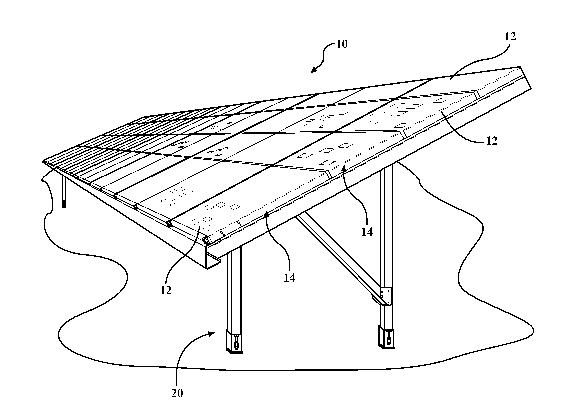
[0013] Figure 1 is a perspective view of a solar array assembly in
accordance with
an aspect of the disclosure;
3
CA 02860607 2014-07-03
WO 2013/138444 PCT/US2013/030797
[0014] Figure 2 is a side view of a mounting structure for a solar panel
assembly in
accordance with an aspect of the disclosure;
[0015] Figure 3 is a perspective view of a mounting structure for a solar
panel
assembly in accordance with an aspect of the disclosure;
[0016] Figure 4 is a cross-sectional view of the mounting structure of
Figure 3 in the
direction of the arrows 4-4;
[0017] Figure 5 is a schematic illustration of a connection of a leg
member to a
foundation structure in accordance with an aspect of the disclosure;
[0018] Figure 6 is a schematic illustration of a connection of a rear leg
member to a
foundation structure as well as a diagonal reinforcement to a rear leg member
in accordance
with an aspect of the disclosure;
[0019] Figure 7 is a schematic illustration of a connection of a leg
member to a
north-south member in accordance with an aspect of the disclosure;
[0020] Figure 8 is a schematic illustration of a connection of a north-
south member
to an east-west member in accordance with an aspect of the disclosure;
[0021] Figure 9A is a schematic illustration a connection of one end of a
rear
support brace to a rear leg member in accordance with an aspect of the
disclosure;
[0022] Figure 9B is a schematic illustration a connection of another end
of a rear
support brace to a rear leg member in accordance with an aspect of the
disclosure;
[0023] Figure 10 is a schematic illustration of an interconnection of
sections of an
east-west member in accordance with an aspect of the disclosure; and
[0024] Figure 11 illustrates a completed solar assembly in accordance
with an
aspect of the disclosure.
4
CA 02860607 2014-07-03
WO 2013/138444 PCT/US2013/030797
DETAILED DESCRIPTION OF THE ENABLING EMBODIMENTS
[0025] Referring to the Figures, wherein like numerals indicate
corresponding parts
throughout the several views, a solar assembly 10 is generally shown. As best
shown in
Figure 1, the solar assembly 10 may include a plurality of panels 12 arranged
in a plurality
of solar arrays 14. In the exemplary embodiment, each panel 12 can include at
least one
photovoltaic (PV) cell for receiving sun rays and converting them into
electricity.
However, it should be appreciated that the solar panels 12 could be any other
type of panel
for converting sun rays into electricity or any other form of useable energy.
It should be
appreciated that the solar assembly 10 could include any number of solar
arrays 14 and
those arrays 14 could be disposed at any desirable angle relative to one
another. According
to an aspect, the solar arrays 14 are supported and oriented in a
predetermined direction and
at a predetermined angle by a mounting structure 20. According to an aspect,
the solar
arrays 14 are installed and maintained at an orientation that maximizes the
solar rays
captured by the PV panels 12 throughout the year. It is thus important that
the mounting
structure 20 can be installed and assembled properly so that the solar arrays
14 are properly
aligned. However, because of ground unevenness, manufacturing tolerances, and
other
variables, alignment of the components and their attachment openings can be
very difficult
thus making installation of the solar assembly 10 a laborious and time
consuming process.
[0026] According to an aspect of the disclosure and with reference
specifically to
Figures 2-4, the mounting structure 20 can include a plurality of north-south
members 22, a
plurality of east-west members 24, a plurality of front leg members 26, a
plurality of rear
leg members 28, a plurality of diagonal reinforcements 30, and a plurality of
rear support
braces 32. The mounting structure 20 may include more or less components as
desired. As
shown in the Figures, the north-south members 22 may have a forward end 40 and
rearward
end 42 with a body extending generally therebetween. The body may be angled
upward in
CA 02860607 2014-07-03
WO 2013/138444 PCT/US2013/030797
the direction from the forward end 40 to the rearward end 42 such that the
solar panels are
positioned at the desired angle. As shown, the mounting structure 20 can have
any number
of north-south members 22 and they can extend at a variety of different upward
angles.
[0027] The components that make the mounting system 20 may be formed of a
variety of different materials and may have a variety of different
configurations. According
to an aspect, as shown in Figures 5 and 6, the front leg members 26 and the
rear leg
members 28 may each employ generally lipped c-shapes. Additionally, as shown
in Figure
7, according to another aspect, the north-south members 22 may have a
generally lipped c-
shape. According to a further aspect, as shown in Figure 4, the east-west
members 24 can
have an open parallelogram shape. According to another aspect shown in Figure
6, the
diagonal reinforcements 30 may have a lipped c-shape. According to a still
further aspect,
as shown in Figures 9A and 9B, the rear support braces 90 may have an 1-shape.
It will be
understood that the illustrated shapes of these structures are merely
exemplary and these
structures can be formed in a multitude of other shapes and configurations as
desired. Also,
according to an aspect, the components may be formed of suitable metal
material.
However, a variety of other suitable materials may be employed.
[0028] Figure 5 through 10 illustrate the various connections that exist
to assemble
the various individual components of the mounting structure 20 according to an
aspect of
the disclosure. It will be understood that the structures effectuating the
connections are
intended to be friction-type bolted connections. However, other suitable
connecting
structures may be employed. According to an aspect, the fasteners may be M10
bolts with
appropriate backing plates. According to another aspect, the M10 bolts can be
torqued to
65 Nm. It will be appreciated that other suitable attachment structures may
also be
employed having a variety of different characteristics and specifications.
6
CA 02860607 2014-07-03
WO 2013/138444 PCT/US2013/030797
[0029] Referring now to Figures 5 and 6, the connection of the leg
members 26, 28
to the foundation structure 50 is schematically illustrated. While the
connection is
described in connection with the front leg members 26, however, the
description applies
equally to the connection of the rear leg members 28, as shown in Figure 6.
According to
an aspect, the connection may effectuated by a mounting bracket 52 that allows
for the
connection of the front leg member 26 at a lower end to the foundation
structure 50.
According to another aspect, the mounting bracket 52 may be generally c-shaped
and fit
around the exterior perimeter of the front leg member 26. According to a
further aspect, a
fastening structure 54 may pass through a back portion 56 of the mounting
bracket 52 to
secure it to the front leg member 26. The back portion 56 may include an
elongated vertical
slot 58 that allows a fastening structure 54 to couple the mounting bracket 52
to the front
leg member 26. The fastening structure 54 may consist of a bolt and a backing
plate with
nuts. The vertical slot 58 can help compensate for any tolerances that may
result from the
manufacture of the components that make up the mounting structure 20 by
allowing the
opening or openings in the front leg member 26 to align with the vertical slot
58 for receipt
of the bolt therethrough. Instead of a slot 58, another suitable opening
configured to allow
for the compensation of tolerances may be employed. According to a further
aspect, the
slot 58 allows for up-down adjustment as well as some angular adjustment of
the front leg
member 26.
[0030] The mounting bracket 52 may also include a base portion 60 for
abutting the
foundation structure 50. Another fastening device 60 may pass through an
opening 62 in
the base potion 60 to securely connect the front leg 26 to the foundation
structure 50.
According to an aspect, the foundation structure 50 can consist of helical
pilings. However,
other suitable structures may also be utilized. The opening 62 can consist of
an elongated
horizontal slot that again allows easier alignment with an opening in the
foundation
7
CA 02860607 2014-07-03
WO 2013/138444 PCT/US2013/030797
structure 50 such that any manufacturing tolerances or other variances are
taken into
account and do not interfere with the proper assembly of the components.
Instead of a slot
62, another suitable opening configured to allow for the compensation of
tolerances by side
adjustment may be employed.
[0031] Figure 6 also illustrates the connection of the diagonal
reinforcement 30 to
the rear leg member 28. According to an aspect, as shown, a bracket 100 can be
employed
to secure the rear leg member 28 to the diagonal reinforcement 30. The bracket
100 may
include one or more openings 102 that are intended to align with openings 104
in the lower
end of the rear leg member 28. One or more fastening devices 106 can be
utilized to secure
the bracket 100 to the rear leg member 28. According to an aspect, the
openings 102 or
openings 104 may consist of an elongated slot or be otherwise enlarged to
allow for the
compensation of tolerances. According to another aspect, the bracket 100 may
also include
one or more openings 108 that are intended to align with openings 112 in a
lower end 110
of the diagonal reinforcement 30. One or more fastening devices 114 can be
utilized to
secure the bracket 100 to the diagonal reinforcement 30. According to a
further aspect, the
openings 108, 112 may consist of an elongated slot or be otherwise enlarged to
allow for the
compensation of tolerances.
[0032] Figure 7 illustrates the connection of each of the front leg
members 26 and
the rear leg members 28 to the north-south members 22. The connection is
described with
respect to the front leg members 26, however the description applies equally
to the
attachment of the rear leg members 28 to the north-south member 22. As shown,
one or
more openings 70 may exist in each of the front leg members 26 and the north-
south
members 22 to allow a fastening device 72 to effectuate a connection
therebetween and
secure the front leg members 26 to the north-south members 22. The fastening
device 72
can include a pair of bolts 74 and a backing plate 76. Instead of openings,
one or more slots
8
CA 02860607 2014-07-03
WO 2013/138444 PCT/US2013/030797
could be employed. It will be appreciated that the fastening device 72 could
have a variety
of different configurations. According to an aspect, the upper end 116 of the
diagonal
reinforcements 30 can are secured to the north-south members 22 in the same
fashion as the
front and rear leg members 26, 28.
[0033] Referring now to Figure 8 which depicts the connection of the
north-south
members 22 to the east-west members 24. According to an aspect, the east-west
members
24 may include a plurality of slots 80 formed therein. According to another
aspect, as the
mounting structure 20 is assembled, one of the slots 80 may overlie an opening
formed in
the north-south members 24 to allow for easy attachment of the members 22, 24
to one
another despite any tolerance variations that may exist as a result of the
individual
manufacture of the components that make up the mounting structure 20 or other
variations.
The securing of these structures is effectuated by a fastening device 82 that
may consist of a
nut 84, a bolt 86 and a backing plate 88. However, other suitable structures
may be
employed. The slot 80 that is utilized to receive the fastening device can
vary depending
upon the degree of tolerance build up. However, according to an aspect, the
assembly of
the mounting structure 20 will not be affected by the tolerances. Instead of
slots 80 other
suitable openings configured to allow for the attachment of the north-south
members 22 to
the east-west members 24 may be employed. Additionally, more or less slots or
openings
may be employed.
[0034] Figures 9A and 9B illustrate the connection of the rear support
brace 90 to
the rear leg members 28. As shown, each end of the rear support brace 90
includes an
opening 92 that is intended to align with corresponding openings in adjacent
rear leg
member 28. According to an aspect, the openings 92 are elongated slots formed
therein that
provide some play such that once the rear support brace 90 is aligned with the
rear leg
member 28, the opening in the rear leg member 28 is accessible through the
slot 92 to allow
9
CA 02860607 2014-07-03
WO 2013/138444 PCT/US2013/030797
utilization of a fastening device 94, thereby in this case a bolt and nut, to
secure the rear
support braces 90 to each of the rear leg members 28. It will be appreciated
that various
different types of fastening devices may be employed to secure these
structures.
[0035] As shown in Figure 10, each east-west member 24 can consist of
multiple
sections. While three sections are disclosed, it will be appreciated that more
or less sections
can be utilized. The sections are preferably connected by a plurality of bolts
and a bracket,
as generally indicated by reference number 98. These sections are connected at
their ends
by the fastening structures that assist in integrating the sections into a
single unitary east-
west member 24.
[0036] Figure 11 generally illustrates the attachment mechanism 120 that
can be
employed to secure the solar panels 12 to the mounting structure 20.
[0037] Obviously, many modifications and variations of the present
invention are
possible in light of the above teachings and may be practiced otherwise than
as specifically
described while within the scope of the appended claims.