Language selection

Search

Patent 2861296 Summary

Third-party information liability

Some of the information on this Web page has been provided by external sources. The Government of Canada is not responsible for the accuracy, reliability or currency of the information supplied by external sources. Users wishing to rely upon this information should consult directly with the source of the information. Content provided by external sources is not subject to official languages, privacy and accessibility requirements.

Claims and Abstract availability

Any discrepancies in the text and image of the Claims and Abstract are due to differing posting times. Text of the Claims and Abstract are posted:

  • At the time the application is open to public inspection;
  • At the time of issue of the patent (grant).
(12) Patent: (11) CA 2861296
(54) English Title: INTEGRATED STRUT AND TURBINE VANE NOZZLE ARRANGEMENT
(54) French Title: AGENCEMENT DE BUSES A PALETTES DE TURBINE ET D'ENTRETOISES INTEGREES
Status: Granted and Issued
Bibliographic Data
(51) International Patent Classification (IPC):
  • F01D 09/02 (2006.01)
  • F01D 09/06 (2006.01)
(72) Inventors :
  • PARADIS, VINCENT (Canada)
  • PATER, CHRIS (Canada)
(73) Owners :
  • PRATT & WHITNEY CANADA CORP.
(71) Applicants :
  • PRATT & WHITNEY CANADA CORP. (Canada)
(74) Agent: NORTON ROSE FULBRIGHT CANADA LLP/S.E.N.C.R.L., S.R.L.
(74) Associate agent:
(45) Issued: 2021-11-23
(22) Filed Date: 2014-08-26
(41) Open to Public Inspection: 2015-04-08
Examination requested: 2019-08-15
Availability of licence: N/A
Dedicated to the Public: N/A
(25) Language of filing: English

Patent Cooperation Treaty (PCT): No

(30) Application Priority Data:
Application No. Country/Territory Date
14/048,426 (United States of America) 2013-10-08

Abstracts

English Abstract

An integrated strut and turbine vane nozzle (ISV) arrangement according to an embodiment, includes a single-piece interturbine duct (ITD) and a plurality of vane nozzle segments removably attached to the ITD. Vane airfoils of the vane nozzle segments in combination with trailing edge portions of the struts, form a vane nozzle integrated with the ITD.


French Abstract

Selon un mode de réalisation, un agencement intégré daubes directrices de turbine avec entretoise de support comprend un conduit interturbine (ITD) monobloc et une pluralité de segments daubes directrices attachés de manière amovible à lITD. Les surfaces portantes des segments daubes directrices en combinaison avec les parties de bord de fuite des entretoises forment une aube directrice intégrée avec lITD.

Claims

Note: Claims are shown in the official language in which they were submitted.


CLAIMS:
1. An integrated strut and turbine vane nozzle (ISV) arrangement for a gas
turbine
engine, comprising:
an interturbine duct (ITD) including inner and outer annular duct walls
arranged
concentrically about an axis and defining an annular flow passage
therebetween, an array of
circumferentially spaced apart struts extending radially across the annular
flow passage, each of
the struts having an airfoil profile with a leading edge and a trailing edge
portion, the inner and
outer annular duct walls each defining a plurality of receivers in respective
downstream end
sections of the inner and outer annular duct walls, each of the receivers
being circumferentially
located between adjacent struts, each of the receivers including a pair of
opposed axial surfaces
circumferentially facing each other, the receivers in the inner or outer duct
wall further including
at least one axially extending slot;
a plurality of vane nozzle segments, each of the vane nozzle segments
including an
inner ring segment, an outer ring segment and a plurality of spaced apart vane
airfoils extending
between and interconnecting the inner and outer ring segments, the vane nozzle
segments
being removably received in the respective receivers of the ITD between the
opposed axial
surfaces of the receivers, the inner or outer ring segment of each of the vane
nozzle segments
having at least one lug slidably axially engaged in the at least one axially
extending slot of an
associated one of the receivers, the vane nozzle segments cooperating with the
downstream
end section of the inner and outer annular duct walls to provide a vane nozzle
integrated with
the ITD, the vane airfoils of the vane ring segments in combination with
trailing edge portions of
the respective struts forming an array of nozzle openings in a downstream end
section of the
annular flow passage, and
a retaining ring mounted in a circumferential groove defined in the inner or
outer annular
duct wall of the ITD, the retaining ring axially retaining the vane nozzle
segments in the
receivers.
2. The integrated strut and turbine vane nozzle (ISV) arrangement as defined
in claim 1
wherein the vane airfoils of the vane nozzle segments are axially positioned
such that trailing
edges of the respective vane airfoils axially align with the trailing edges of
the respective struts.
3. The integrated strut and turbine vane nozzle (ISV) arrangement as defined
in claim 1
wherein a nozzle opening dimension measured circumferentially between trailing
edges of
- 11 -
Date Recue/Date Received 2021-03-26

adjacent vane airfoils is substantially identical to a nozzle opening
dimension measured
circumferentially between the trailing edge of each of the struts and a
trailing edge of one of the
vane airfoils which is adjacent the strut.
4. The integrated strut and turbine vane nozzle (ISV) arrangement as defined
in claim 1
wherein the at least one axially extending slot comprises a plurality of slots
defined in a number
of the receivers, the slots receiving the at least one lug of the respective
vane nozzle segments
to radially and circumferentially retain the respective vane nozzle segment in
position such that
the inner ring segments and the outer ring segments form part of the
respective inner and outer
annular duct walls of the ITD.
5. The integrated strut and turbine vane nozzle (ISV) arrangement as defined
in claim 4
wherein the at least one lug is disposed on each of the outer ring segments
and wherein the
slots are defined in the outer annular duct wall, and wherein the at least one
lug includes a pair
of lugs projecting outwardly from opposed circumferential ends of each outer
ring segments.
6. The integrated strut and turbine vane nozzle (ISV) arrangement as defined
in claim 4
wherein the at least one lug is disposed on each of the inner ring segments
and wherein the
slots are defined in the inner annular duct wall.
7. The integrated strut and turbine vane nozzle (ISV) arrangement as defined
in claim 1
wherein the inner ring segments each comprise circumferentially opposed ends
defining two
end surfaces facing away from each other, the at least one lug comprising
opposed lugs
projecting circumferentially away from each of the end surfaces, and wherein
the axially
extending slot comprises a pair of axial slots defined on the opposed axial
surfaces of each
receiver in the inner annular duct wall for receiving axial insertion of the
respective one of the
lugs to thereby radially and circumferentially retain the vane nozzle segments
in position with
respect to the ITD.
8. The integrated strut and turbine vane nozzle (ISV) arrangement as defined
in claim 1
wherein the outer ring segments each comprise circumferentially opposed ends
defining two
end surfaces facing away from each other, the at least one lug comprising lugs
projecting
circumferentially away from each of the end surfaces, and wherein the at least
one axially
extending slot comprises an axial slot defined on each of the opposed axial
surfaces of the
receivers in the outer annular duct wall for receiving axial insertion of the
respective one of the
- 12 -
Date Recue/Date Received 2021-03-26

lugs to thereby radially and circumferentially retain the vane nozzle segments
in position with
respect to the ITD.
9. The integrated strut and turbine vane nozzle (ISV) arrangement as defined
in claim 1
wherein the retaining ring is in contact with a circumferentially extending
radial surface of the
respective vane nozzle segments to thereby axially retain the vane nozzle
segments in position
with respect to the ITD.
10. The integrated strut and turbine vane nozzle (ISV) arrangement as defined
in claim 9
wherein the circumferential groove is defined in the inner annular duct wall.
11. The integrated strut and turbine vane nozzle (ISV) arrangement as defined
in claim 9
wherein each of the vane nozzle segments comprises a flange segment projecting
radially away
from the inner ring segment, the flange segment defining said
circumferentially extending radial
surface.
12. The integrated strut and turbine vane nozzle (ISV) arrangement as defined
in claim 1
wherein the ITD is a single-piece component which includes said inner and
outer annular duct
walls, said struts and a second plurality of vane airfoils radially extending
between and
interconnecting the inner and outer annular duct walls, the vane airfoils of
the ITD being
identical to the vane airfoils of the vane nozzle segments in shape and size,
trailing edges of the
vane airfoils of the ITD axially aligning with the trailing edges of the
struts.
13. The integrated strut and turbine vane nozzle (ISV) arrangement as defined
in claim
12 wherein said vane airfoils of the ITD are arranged in pairs, each of the
struts being flanked
by a pair of the vane airfoils of the ITD.
14. The integrated strut and turbine vane nozzle (ISV) arrangement as defined
in claim 1
wherein a leading edge of the respective vane airfoils is disposed downstream
of the leading
edge of the respective struts in the annular flow passage.
15. The integrated strut and turbine vane nozzle (ISV) arrangement as defined
in claim 1
wherein the receivers are defined as a plurality of recesses in the outer
annular duct wall and a
plurality of slots in the inner annular duct wall.
16. The integrated strut and turbine vane nozzle (ISV) arrangement as defined
in claim 1
wherein each of the vane nozzle segments comprises a T shaped dovetail
configuration on the
- 13 -
Date Recue/Date Received 2021-03-26

outer ring segment and wherein the ITD comprises a T shaped groove for
receiving axial
insertion of the T shaped dovetail configuration.
17. An integrated strut and turbine vane nozzle (ISV) arrangement for a gas
turbine
engine, comprising:
a single-piece interturbine duct (ITD) including inner and outer annular duct
walls
arranged concentrically about an axis and defining an annular flow passage
therebetween, an
array of circumferentially spaced apart struts extending radially across the
annular flow
passage, each of the struts having an airfoil profile defining a leading edge
and a trailing edge
thereof, the inner annular duct wall defining a plurality of slots in a
downstream end section
thereof, the outer annular duct wall defining a plurality of recesses in a
downstream end section
thereof, each of the slots and recesses defining two circumferentially spaced
apart axial
surfaces facing each other, each of the slots and recesses being
circumferentially located
between adjacent struts;
a plurality of vane nozzle segments, each of the vane nozzle segments
including an
inner ring segment, an outer ring segment and a plurality of spaced apart vane
airfoils extending
between and interconnecting the inner and outer ring segments, each of the
vane airfoils
defining a leading edge and a trailing edge, the inner ring segments being
axially removably
received between the two axial surfaces of the respective slots of the inner
annular duct wall,
and the outer ring segment being axially removably received between the two
axial surfaces of
the respective recesses of the outer annular duct wall, thereby forming in
combination with the
downstream end section of the inner and outer annular duct walls, a vane
nozzle integrated with
the ITD, the vane airfoils of the vane ring segments in combination with
trailing edge portions of
the respective struts forming an array of nozzle openings in a downstream end
section of the
annular flow passage, the leading edges of the respective vane airfoils being
disposed
downstream of the leading edges of the respective struts, the trailing edges
of the respective
vane airfoils axially aligning with the trailing edges of the struts, wherein
each of the vane nozzle
segments has at least one lug axially engaged in a corresponding axial groove
defined in the
slots, the engagement of the at least one lug with the corresponding axial
groove radially and
circumferentially retaining the vane nozzle segments in position with respect
to the ITD; and
a retaining ring received in a circumferential groove defined in the ITD, the
retaining ring
axially retaining the respective vane nozzle segments into the slots and
recesses in the inner
annular duct wall and the outer annular duct wall of the ITD.
- 14 -
Date Recue/Date Received 2021-03-26

18. An integrated strut and turbine vane nozzle (ISV) arrangement for a gas
turbine
engine, comprising:
a single-piece interturbine duct (ITD) including inner and outer annular duct
walls
arranged concentrically about an axis and defining an annular flow passage
therebetween, an
array of circumferentially spaced apart struts extending radially across the
annular flow
passage, each of the struts having an airfoil profile defining a leading edge
and a trailing edge
thereof, a plurality of pairs of vane airfoils radially extending between and
interconnecting the
inner and outer annular duct walls, each of the struts being flanked by a pair
of the vane airfoils,
each of the vane airfoils defining a leading edge and a trailing edge thereof,
the inner annular
duct wall defining a plurality of slots in a downstream end section thereof,
the outer annular duct
wall defining a plurality of recesses in a downstream end section thereof,
each of the slots and
recesses defining two circumferentially spaced apart axial surfaces facing
each other, each of
the slots and recesses being circumferentially located between adjacent pairs
of the vane
airfoils;
a plurality of vane nozzle segments, each of the vane nozzle segments
including an
inner ring segment, an outer ring segment and a second plurality of spaced
apart vane airfoils
extending between and interconnecting the inner and outer ring segments, each
of the vane
airfoils defining a leading edge and a trailing edge, the inner ring segments
being removably
received between the two axial surfaces of the respective slots of the inner
annular duct wall,
and the outer ring segment being removably received between the two axial
surfaces of the
respective recesses of the outer annular duct wall, thereby forming in
combination with the
downstream end section of the inner and outer annular duct walls, a vane
nozzle integrated with
the ITD, the vane airfoils of the vane ring segments and the vane airfoils of
the ITD in
combination with trailing edge portions of the respective struts forming an
array of nozzle
openings in a downstream end section of the annular flow passage, the trailing
edges of the
vane airfoils of the respective ITD and vane nozzle segments axially aligning
with the trailing
edges of the struts, wherein each of the vane nozzle segments has at least one
lug axially
engaged in a corresponding axial groove defined in the slots, the engagement
of the at least
one lug with the corresponding axial groove radially and circumferentially
retaining the vane
nozzle segments in a position with respect to the ITD; and
a retaining ring received in a circumferential groove defined in the ITD, the
retaining ring
axially retaining the respective vane nozzle segments to the single-piece ITD.
- 15 -
Date Recue/Date Received 2021-03-26

19. An integrated strut and turbine vane nozzle (ISV) arrangement for a gas
turbine
engine, comprising:
an interturbine duct (ITD) including inner and outer annular duct walls
arranged
concentrically about an axis and defining an annular flow passage
therebetween, an array of
circumferentially spaced apart struts extending radially across the annular
flow passage, a
plurality of receivers defined in respective downstream end sections of the
inner and outer
annular duct walls, each of the receivers being circumferentially located
between adjacent
struts, each of the receivers including a pair of opposed axial surfaces
circumferentially facing
each other, the receivers in the inner or outer duct walls further including
at least one axially
extending slot;
a plurality of vane nozzle segments, each of the vane nozzle segments
including an
inner ring segment, an outer ring segment and a plurality of spaced apart vane
airfoils extending
between and interconnecting the inner and outer ring segments, the vane nozzle
segments
being removably received in the respective receivers of the ITD between the
opposed axial
surfaces of the receivers, the inner ring segment or the outer ring segment of
the vane nozzle
segments having at least one lug slidably axially engaged in the at least one
axially extending
slot of an associated one of the receivers, the vane nozzle segments
cooperating with the
downstream end section of the inner and outer annular duct walls to provide a
vane nozzle
integrated with the ITD, the vane airfoils of the vane ring segments in
combination with trailing
edge portions of the respective struts forming an array of nozzle openings in
a downstream end
section of the annular flow passage; and
a retaining ring axially holding the plurality of vane nozzle segments in
position with
respect to the ITD, the retaining ring engaged in a groove defined in a
radially outer surface of
the inner annular duct wall of the ITD.
20. The ISV arrangement defined in claim 19, wherein the vane airfoils of the
vane
nozzle segments are axially positioned such that trailing edges of the
respective vane airfoils
axially align with corresponding trailing edges of the struts.
21. The ISV arrangement defined in claim 19, wherein a nozzle opening
dimension
measured circumferentially between trailing edges of adjacent vane airfoils is
configured to
match a nozzle opening dimension measured circumferentially between a trailing
edge of each
of the struts and a trailing edge of one of the vane airfoils which is
adjacent the strut.
- 16 -
Date Recue/Date Received 2021-03-26

22. The ISV arrangement defined in claim 19, wherein the at least one lug
includes a
pair of lugs projecting outwardly from opposed circumferential ends of each
outer ring
segments, and wherein the at least one axially extending slot of each receiver
includes a pair of
slots for receiving the pair of lugs.
23. The ISV arrangement defined in claim 19, wherein the inner ring segments
each
comprise circumferentially opposed ends defining two end surfaces facing away
from each
other, the at least one lug comprising opposed lugs projecting
circumferentially away from each
of the end surfaces, and wherein the at least one axially extending slot
comprises a pair of axial
slots defined on the opposed axial surfaces of each receiver in the inner
annular duct wall for
receiving axial insertion of the respective one of the opposed lugs.
24. The ISV arrangement defined in claim 19, wherein the outer ring segments
each
comprise circumferentially opposed ends defining two end surfaces facing away
from each
other, the at least one lug comprising lugs projecting circumferentially away
from each of the
end surfaces, and wherein the at least one axially extending slot comprises an
axial slot defined
on each of the opposed axial surfaces of the receivers in the outer annular
duct wall for
receiving axial insertion of the respective one of the lugs.
25. The ISV arrangement defined in claim 19, wherein the retaining ring is in
contact with
a circumferentially extending radial surface of the respective vane nozzle
segments.
26. The ISV arrangement defined in claim 25, wherein each of the vane nozzle
segments comprises a flange segment projecting radially away from the inner
ring segment, the
flange segment defining said circumferentially extending radial surface.
27. The ISV arrangement defined in claim 19 wherein the ITD is a single-piece
component which includes said inner and outer annular duct walls, said struts
and a plurality of
vane airfoils radially extending between and interconnecting the inner and
outer annular duct
walls, the vane airfoils of the ITD being identical to the vane airfoils of
the vane nozzle segments
in shape and size, trailing edges of the vane airfoils of the ITD axially
aligning with trailing edges
of the struts.
28. The ISV arrangement defined in claim 27 wherein said vane airfoils of the
ITD are
arranged in pairs, each of the struts being flanked by a pair of the vane
airfoils of the ITD.
- 17 -
Date Recue/Date Received 2021-03-26

29. The ISV arrangement defined in claim 19 wherein a leading edge of the
respective
vane airfoils is disposed downstream of a leading edge of the respective
struts in the annular
flow passage.
30. The ISV arrangement defined in claim 19, wherein the receivers are defined
as a
plurality of recesses in the outer annular duct wall and a plurality of slots
in the inner annular
duct wall.
31. The ISV arrangement defined in claim 19, wherein the at least one lug of
each of the
vane nozzle segments comprises a T shaped dovetail configuration on the outer
ring segment,
and wherein the at least one axially extending slot of each of the receivers
on the ITD comprises
a T shaped groove for receiving axial insertion of the T shaped dovetail
configuration.
32. An integrated strut and turbine vane nozzle (ISV) arrangement for a gas
turbine
engine, comprising:
an interturbine duct (ITD) including inner and outer annular duct walls
arranged
concentrically about an axis and defining an annular flow passage
therebetween, an array of
circumferentially spaced apart struts extending radially across the annular
flow passage, the
inner annular duct wall defining a plurality of slots in a downstream end
section thereof, the
outer annular duct wall defining a plurality of recesses in a downstream end
section thereof,
each of the slots and recesses defining two circumferentially spaced apart
axial surfaces facing
each other, each of the slots and recesses being circumferentially located
between adjacent
struts;
a plurality of vane nozzle segments, each of the vane nozzle segments
including an
inner ring segment, an outer ring segment and a plurality of spaced apart vane
airfoils extending
between and interconnecting the inner and outer ring segments, the inner ring
segments being
axially removably received between the two axial surfaces of the respective
slots of the inner
annular duct wall, and the outer ring segment being axially removably received
between the two
axial surfaces of the respective recesses of the outer annular duct wall,
thereby forming in
combination with the downstream end section of the inner and outer annular
duct walls, a vane
nozzle integrated with the ITD, the vane airfoils of the vane ring segments in
combination with
trailing edge portions of the respective struts forming an array of nozzle
openings in a
downstream end section of the annular flow passage, wherein at least one of
the vane nozzle
- 18 -
Date Recue/Date Received 2021-03-26

segments has at least one lug axially engaged in a corresponding axial groove
defined in the
slots or recesses; and
a retaining ring engaged in a groove defined in a radially outer surface of
the inner
annular duct wall of the ITD and retaining the respective vane nozzle segments
into the slots
and recesses in the inner annular duct wall and the outer annular duct wall of
the ITD.
33. An integrated strut and turbine vane nozzle (ISV) arrangement for a gas
turbine
engine, comprising:
a single-piece interturbine duct (ITD) including inner and outer annular duct
walls
arranged concentrically about an axis and defining an annular flow passage
therebetween, an
array of circumferentially spaced apart struts extending radially across the
annular flow
passage, each of the struts having an airfoil profile defining a leading edge
and a trailing edge
thereof, a plurality of pairs of ITD vane airfoils radially extending between
and interconnecting
the inner and outer annular duct walls, each of the struts being flanked by a
pair of the ITD vane
airfoils, each of the ITD vane airfoils defining a leading edge and a trailing
edge thereof, the
inner annular duct wall defining a plurality of slots in a downstream end
section thereof, the
outer annular duct wall defining a plurality of recesses in a downstream end
section thereof,
each of the slots and recesses defining two circumferentially spaced apart
axial surfaces facing
each other, each of the slots and recesses being circumferentially located
between adjacent
pairs of the ITD vane airfoils;
a plurality of vane nozzle segments, each of the vane nozzle segments
including an
inner ring segment, an outer ring segment and a plurality of spaced apart vane
airfoils extending
between and interconnecting the inner and outer ring segments, each of the
vane airfoils
defining a leading edge and a trailing edge, the inner ring segments being
removably received
between the two axial surfaces of the respective slots of the inner annular
duct wall, and the
outer ring segment being removably received between the two axial surfaces of
the respective
recesses of the outer annular duct wall, wherein at least one of the vane
nozzle segments has
at least one lug axially engaged in a corresponding axial groove defined in
the slots or recesses,
the engagement of the at least one lug with the corresponding axial groove
radially and
circumferentially retaining the vane nozzle segments in position with respect
to the ITD; and
a retaining ring axially retaining the respective vane nozzle segments on the
single-piece
ITD, the retaining ring engaged in a groove defined in a radially outer
surface of the inner
annular duct wall of the single-piece ITD.
- 19 -
Date Recue/Date Received 2021-03-26

Description

Note: Descriptions are shown in the official language in which they were submitted.


CA 02861296 2014-08-26
INTEGRATED STRUT AND TURBINE VANE NOZZLE ARRANGEMENT
TECHNICAL FIELD
[0001] The application
relates generally to gas turbine engines and, more
particularly, to integrated strut and turbine vane nozzle arrangements in such
engines.
BACKGROUND OF THE ART
[0002] Gas turbine
engine ducts may have struts in the gas flow path, as well as
vanes for guiding a gas flow through the duct. An integrated strut and turbine
vane
nozzle (ISV) forms a portion of a conventional turbine engine gas path. The
ISV
usually includes an outer and an inner ring connected together with struts
which are
airfoil-shaped in order to protect support structures and/or service lines in
the inter
turbine duct (ITD) portion, and airfoils/vanes in the turbine vane nozzle
portion. The
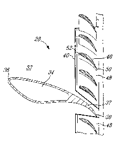
integration is achieved by combining the airfoil shaped strut with the airfoil
shape of a
corresponding one of the vanes. The ISV can be made from one integral piece or
from an assembly of multiple pieces. However, it is more difficult to adjust
the flow
through the vane nozzle airfoil if the ISV is a single integral piece. A
multiple-piece
approach with segments of turbine vane nozzles allows the possibility of
mixing
different classes of segments in the ISV to achieve proper engine flow.
However, a
significant challenge in a multiple-piece arrangement of an ISV, is to
minimize
interface mismatch between the parts in order to reduce engine performance
losses.
Conventionally, complex manufacturing techniques are used to minimize this
mismatch between the parts of the integrated strut and vane. In addition,
mechanical joints such as bolts are conventionally used, but are problematic
because of potential bolt seizing in the hot environment of the ISV.
SUMMARY
[0003] In one aspect,
there is provided an integrated strut and turbine vane nozzle
(ISV) arrangement for a gas turbine engine, comprising: an interturbine duct
((ID)
including inner and outer annular duct walls arranged concentrically about an
axis
and defining an annular flow passage therebetween, an array of
circumferentially
-1-

CA 02861296 2014-08-26
spaced apart struts extending radially across the annular flow passage, each
of the
struts having an airfoil profile defining a leading edge and a trailing edge
thereof, the
inner and outer annual duct walls each defining a plurality of receivers in a
respective
downstream end section of the inner and outer annular duct walls, each of the
receivers being circumferentially located between adjacent struts; and a
plurality of
vane nozzle segments, each of the vane nozzle segments including an inner ring
segment, an outer ring segment and a plurality of spaced apart vane airfoils
extending between and interconnecting the inner and outer ring segments, the
vane
nozzle segments being removably received in the respective receivers of the
ITD,
thereby forming in combination with the downstream end section of the inner
and
outer annular duct walls, a vane nozzle integrated with the ITD, the vane
airfoils of
the vane ring segments in combination with trailing edge portions of the
respective
struts forming an array of nozzle openings in a downstream end section of the
annular flow passage.
[0004] In another
aspect, there is provided an integrated strut and turbine vane
nozzle (ISV) arrangement for a gas turbine engine, comprising: a single-piece
interturbine duct (ITD) including inner and outer annular duct walls arranged
concentrically about an axis and defining an annular flow passage
therebetween, an
array of circumferentially spaced apart struts extending radially across the
annular
flow passage, each of the struts having an airfoil profile defining a leading
edge and
a trailing edge thereof, the inner annular duct wall defining a plurality of
slots in a
downstream end section thereof, the outer annular duct wall defining a
plurality of
recesses in a downstream end section thereof, each of the slots and recesses
defining two circumferentially spaced apart axial surfaces facing each other,
each of
the slots and recesses being circumferentially located between adjacent
struts; a
plurality of vane nozzle segments, each of the vane nozzle segments including
an
inner ring segment, an outer ring segment and a plurality of spaced apart vane
airfoils extending between and interconnecting the inner and outer ring
segments,
each of the vane airfoils defining a leading edge and a trailing edge, the
inner ring
segments being removably received between the two axial surfaces of the
respective
slots of the inner annular duct wall, and the outer ring segment being
removably
received between the two axial surfaces of the respective recesses of the
outer
annular duct wall, thereby forming in combination with the downstream end
section
-2-

the inner and outer annular duct walls, a vane nozzle integrated with the ITD,
the
vane airfoils of the vane ring segments in combination with trailing edge
portions of
the respective struts forming an array of nozzle openings in a downstream end
section of the annular flow passage, the leading edges of the respective vane
airfoils
being disposed downstream of the leading edges of the respective struts, the
trailing
edges of the respective vane airfoils axially aligning with the trailing edges
of the
struts; and a retainer retaining the respective vane nozzle segments to the
single-
piece ITD.
[0005] In a
further aspect, there is provided an integrated strut and turbine vane
nozzle (ISV) arrangement for a gas turbine engine, comprising: a single-piece
interturbine duct (ITD) including inner and outer annular duct walls arranged
concentrically about an axis and defining an annular flow passage
therebetween, an
array of circumferentially spaced apart struts extending radially across the
annular
flow passage, each of the struts having an airfoil profile defining a leading
edge and
a trailing edge thereof, a plurality of pairs of vane airfoils radially
extending between
and interconnecting the inner and outer annular duct walls, each of the struts
being
flanked by a pair of the vane airfoils, each of the vane airfoils defining a
leading edge
and a trailing edge thereof, the inner annular duct wall defining a plurality
of slots in a
downstream end section thereof, the outer annular duct wall defining a
plurality of
recesses in a downstream end section thereof, each of the slots and recesses
defining two circumferentially spaced apart axial surfaces facing each other,
each of
the slots and recesses being circumferentially located between adjacent pairs
of the
vane airfoils; a plurality of vane nozzle segments, each of the vane nozzle
segments
including an inner ring segment, an outer ring segment and a plurality of
spaced
apart vane airfoils extending between and interconnecting the inner and outer
ring
segments, each of the vane airfoils defining a leading edge and a trailing
edge, the
inner ring segments being removably received between the two axial surfaces of
the
respective slots of the inner annular duct wall, and the outer ring segment
being
removably received between the two axial surfaces of the respective recesses
of the
outer annular duct wall, thereby forming in combination with the downstream
end
section of the inner and outer annular duct walls, a vane nozzle integrated
with the
ITD, the vane airfoils of the vane ring segments and the vane airfoils of the
ITD in
combination with trailing edge portions of the respective struts forming an
array of
nozzle openings in a downstream end section of the annular flow passage, the
- 3 -
Date Recue/Date Received 2021-03-26

leading edges of the vane airfoils of the respective ITD and vane nozzle
segments
being disposed downstream of the leading edges of the respective struts in the
annular flow passage, the trailing edges of the vane airfoils of the
respective ITD and
vane nozzle segments axially aligning with the trailing edges of the struts;
and a
retainer retaining the respective vane nozzle segments to the single-piece
ITD.
DESCRIPTION OF THE DRAWINGS
[0006] Reference is now made to the accompanying figures in which:
[0007] FIG. 1 is a schematic side cross-sectional view of a gas turbine
engine;
[0008] FIG. 2 is a cross-sectional view of an integrated strut and
turbine vane
nozzle (ISV) suitable for forming a portion of a turbine engine gas path of
the engine
shown in FIG. 1;
[0009] FIG. 3 is a cross-sectional view taken along line 3-3 in FIG. 2;
[0010] FIG. 4 is a partial isometric view of an inter turbine duct (ITD)
in the ISV of
FIG. 3 according to one embodiment;
[0011] FIG. 5 is an isometric view of a vane nozzle segment for
attachment to the
ITD of FIG. 4;
[0012] FIG. 6 is a partial isometric view of an integrated strut and
turbine vane
nozzle (ISV) including the ITD of FIG. 4 and the vane nozzle segments of FIG.
5;
[0013] FIG. 7 is a partial isometric view of an ISV according to another
embodiment;
[0014] FIG. 8 is a partial isometric view of an ITD of the ISV of FIG. 3,
according
to a further embodiment;
[0015] FIG. 9 is an isometric view of a vane nozzle segment for
attachment to the
ITD of FIG. 8; and
[0016] FIG. 10 is a partial isometric view of an ISV including the ITD of
FIG. 8 and
the vane nozzle segment as shown in FIG. 9.
[0017] It will be noted that throughout the appended drawings, like
features will be
identified by like reference numerals.
- 4 -
Date Recue/Date Received 2021-03-26

CA 02861296 2014-08-26
DETAILED DESCRIPTION
[0018] FIG. 1
illustrates a gas turbine engine 10 of a type preferably provided for
use in subsonic flight, generally comprising in serial flow communication a
fan 12
through which ambient air is propelled, a multistage compressor 14 for
pressurizing
the air, a combustor 16 in which the compressed air is mixed with fuel and
ignited for
generating an annular stream of hot combustion gases, and a turbine section 18
for
extracting energy from the combustion gases.
[0019] The turbine
engine 10 includes a first casing 20 which encloses the turbo
machinery of the engine and a second outer casing 22 extending outwardly of
the
first casing 20, thereby defining an annular bypass passage 24 therebetween.
The
air propelled by the fan 12 is split into a first portion which flows around
the first
casing 20 within the bypass passage 24, and a second portion which flows
through a
core flow path 26. The core flow path 26 is defined within the first casing 20
and
allows the flow to circulate through the multistage compressor 14, the
combustor 16
and the turbine section 18 as described above.
[0020] Throughout this
description, the axial, radial and circumferential directions
are respectively defined with respect to a central axis 27, and to the radius
and
circumference of the gas turbine engine 10. The terms
"upstream" and
"downstream" are defined with respect to the flow direction through the core
flow
path 26.
[0021] FIGS. 2-3 show an
integrated strut and turbine vane nozzle (ISV)
arrangement 28 suitable for forming a portion of the core flow path 26 of the
engine
shown in FIG. 1. For instance, the ISV arrangement 28 may form part of a mid
turbine frame system for directing a gas flow from a high pressure turbine
assembly
to a low pressure turbine assembly. However, it is understood that the ISV
arrangement 28 may also be used in other sections of an engine.
[0022] It is also
understood that the ISV arrangement 28 is not limited to turbofan
applications. Indeed, the ISV arrangement 28 may be installed in other types
of gas
turbine engines such as turboprops, turboshafts and axial power units (APU).
[0023] The ISV
arrangement 28 generally comprises a radially outer annular duct
wall 30 and a radially inner annular duct wall 32 concentrically disposed
about the
engine central axis 27 (FIG. 1) and defines an annular flow passage 33
-5-

CA 02861296 2014-08-26
therebetween. The annular flow passage 33 defines an axial portion of the core
flow
path 26 (FIG. 1).
[0024] It can be appreciated that a plurality of circumferentially spaced
apart struts
34 (only one shown in FIGS. 2 and 3) extend radially between and interconnect
the
outer and inner annular duct walls 30, 32 according to one embodiment. The
struts
34 may have a hollow airfoil shape including a pressure side wall (not
numbered)
and a suction side wall (not numbered) defined between a leading edge 36 and a
trailing edge 38 (FIG. 3) of the strut. Support structures 39 and service
lines (not
shown) may extend internally through the hollow struts 34. The struts 34 may
be
used to transfer loads and/or to protect a given structure (e.g. service
lines) from
high temperature gases flowing through the annular flow passage 33. Therefore,
the
outer and inner annular duct walls 30, 32 with the struts 34, generally form
an
interturbine duct (ITD) 29.
[0025] The array of circumferentially spaced apart struts 34 extends
radially
across the annular flow passage 33 with the trailing edge 38 thereof located
downstream of the leading edge 36 thereof, within the annular flow passage 33,
for
example at a respective downstream end section (not numbered) of the inner and
outer annular duct walls 32, 30.
[0026] The outer and inner annular duct walls 30, 32 and the struts 34 may
form a
single-piece component of the ITD 29.
[0027] Referring to FIGS. 2-6, a plurality of vane nozzle segments 40 are
provided. Each vane nozzle segment 40 may be a single-piece component
including
a circumferential inner ring segment 42, a circumferential outer ring segment
44 and
a plurality of circumferentially spaced apart vane airfoils 46 extending
radially
between and interconnecting the inner and outer ring segments 42, 44. The vane
nozzle segments 40 may be removably attached to the ITD 29, and may be
received,
for example in respective receivers of the ITD 29 (which will be further
described in
detail hereinafter). Therefore, the vane nozzle segments 40 in combination
with the
downstream end section of the inner and outer annular duct walls 32, 30, form
a
vane nozzle (not numbered) of the ISV arrangement 28. The vane airfoils 46 of
the
vane nozzle segments 40 together with trailing edge portions 37 of the
respective
-6-

CA 02861296 2014-08-26
struts 34 form an array of nozzle openings 48 in a downstream end section of
the
annular flow passage 33.
[0028] A nozzle opening dimension measured circumferentially between
trailing
edges 50 of adjacent vane airfoils 46 may be substantially identical to a
nozzle
opening dimension measured circumferentially between the trailing edge 38 of
each
of the struts 34 and a trailing edge 50 of one of the vane airfoils 46 which
is adjacent
the strut 34. According to this embodiment, the vane airfoils 46 of the vane
nozzle
segments 40 may be axially positioned such that the trailing edges of the
respective
vane airfoils 46 axially align with the trailing edges 38 of the respective
struts 34,
while a leading edge 52 of the respective vane airfoils 46 is disposed in the
annular
flow passage 33 downstream of the leading edge 36 of the respective strut 34.
Each
inner ring segment 42 may include circumferentially opposed ends defining
thereon,
two end surfaces 54 facing away from each other. A lug member 56 projects
circumferentially away from each of the end surfaces 54. Each circumferential
outer
ring segment 44 may include circumferentially opposed ends defining two end
surfaces 58 facing away from each other, without projecting lugs members.
[0029] The receivers defined in the outer annular duct wall 30 may each be
defined as a recess 60 in the downstream end section of the outer annular duct
wall
30 (FIG. 4) including opposed axial surfaces 62 circumferentially facing each
other.
The receivers defined in the inner annular duct wall 32 may each be defined as
a slot
64, including opposed axial surfaces 66 circumferentially facing each other.
An axial
groove 68 may be defined on each of the axial surfaces 66 for receiving axial
insertion of the respective one of the lug members 56 when the inner ring
segments
42 are removably received between the two axial surfaces 66 of the respective
slots
64 and the outer ring segments 44 are removably received between the two axial
surfaces 62 of the respective recesses 60 of the outer annular duct wall 30.
The lug
members 56 and the axial groove 68 in engagement, provide radial and
circumferential retention of the vane nozzle segments 40 in position with
respect to
the ITD 29, as shown in FIG. 6.
[0030] According to another embodiment as shown in FIG. 7, the ITD 29 and
the
vane nozzle segments 40 are similar to the ITD 29 and the vane nozzle segments
40
shown in FIGS. 4-6 but the lug/groove engagement of the embodiment shown in
FIG. 7 which is similar to the lug/groove engagement of the embodiment of
FIGS. 4-
-7-

CA 02861296 2014-08-26
6, is defined between the respective outer ring segments 44 and the outer
annular
duct wall 30 instead of between the respective inner ring segments 42 and the
inner
annular duct wall 32 as shown in FIG. 6. In particular, the inner ring segment
42 of
the embodiment shown in FIG. 7, defines axial surfaces on two opposed ends
thereof, facing away from each other, without lug members. The outer ring
segment
44 of the vane nozzle segment 40 includes respective lug members 55,
projecting
away from axial surfaces (not numbered) which are defined on the opposed two
ends of the outer ring segment 44, thereby facing away from each other. The
lug
members 55 may be axially inserted into axial grooves 69 defined in axial
surfaces
(not numbered) of the recess 60.
[0031] The ITD 29 may further define a circular or annular groove 70 (see
FIGS. 2
and 4) in the inner annular duct wall 32 for releasably receiving a retaining
ring 72,
such as a split ring. The retaining ring 72 when received in the
circumferential or
annular groove 70 may be in contact with a circumferentially extending radial
surface
of the respective vane nozzle segments 40. For example, the circumferentially
extending radial surface may be defined on a flange segment 74 projecting
radially
from the inner ring segment 42. Therefore, the retaining ring 72 releasably
received
circular or annular groove 70, axially retains the vane nozzle segments 40 in
position
with respect to the ITD 29.
[0032] In such a multiple-piece arrangement of the ISV 28, the combination
of the
airfoil shaped strut 34 with a corresponding vane airfoil is achieved by a
single-piece
strut component, thereby eliminating interface mismatch between the parts
because
there is no interface between the strut and the combined one of the vane
airfoils
which is a trailing edge portion, and part of the strut. Therefore, the
interchange of
the circumferential vane nozzle segments in the ISV to achieve proper engine
flow
will not result in any interface mismatch between the struts and the
respective
combined vane airfoils.
[0033] FIGS. 8-10 illustrate another embodiment of the ISV arrangement 28'
similar to the ISV arrangement 28 shown in FIGS. 2-7. The components and
features of ISV arrangement 28' which are similar to those shown in FIGS. 2-7
are
indicated by like numeral references and will not be described hereinafter.
The
-8-

CA 02861296 2014-08-26
description of the ISV 28 below will be focused on the differences between the
ISV
arrangment 28' and the ISV arrangement 28.
[0034] In the ISV arrangement 28' the single-piece ITD 29' may include not
only
the inner and outer annular duct walls 32, 30, and the struts 34, but also a
plurality of
vane airfoils 46' radially extending between and interconnecting the inner and
outer
annular duct walls 32, 30. The vane airfoils 46' of the ITD 29' (FIG. 8) are
substantially identical in shape and size to the vane airfoils 46 of the vane
nozzle
segments 40' (FIG. 9). Similar to the vane nozzle segments 40 (FIG. 5), the
vane
nozzle segments 40' (FIG. 9) include circumferential inner and outer ring
segments
42 and 44, interconnected by the vane airfoils 46. The trailing edges of the
vane
airfoils 46' of the ITD 29' may be axially aligned with the trailing edges of
the struts
34, as well as with the trailing edges of the vane airfoils 46 of the vane
nozzle
segments 40' when the vane nozzle segments 40' are attached to the ITD 29', in
a
manner similar to that of the ISV arrangement 28 shown in FIGS. 2-7. It should
be
understood that the leading edge of the vane airfoils 46' of the ITD 29', may
axially
align with the leading edges of the vane airfoils 46 of the vane nozzle
segments 40'.
[0035] According to this embodiment, each of the struts 34 of the ISV
arrangment
28' is flanked by a pair of vane airfoils 46'. Also, each of the slots 64
defined in the
inner annular duct wall 32 and each of the recesses 60 defined in the outer
annular
duct wall 30 are circumferentially located between adjacent pairs of the vane
airfoils
46'. In this ISV arrangement 28' the vane nozzle segments 40' have fewer
airfoils 46
than the vane nozzle segments 40 shown in FIGS. 2-7.
[0036] Alternative to the lug and groove engagement used in the ISV
arrangement 28 of FIGS. 2-7, a T-shaped dovetail 76 may be provided on the
outer
ring segment 44, for example at a middle area of each of the vane nozzle
segments
40'. The T-shaped dovetail 76 extending axially for axial insertion into an
axial T-
shaped groove 78 defined in the outer annular duct wall 30 of the ITD 29', for
example in a central area of the bottom of each of the recesses 60.
[0037] The above description is meant to be exemplary only, and one skilled
in
the art will recognize that changes may be made to the embodiments described
without departing from the scope of the described subject matter. It is also
understood that various combinations of the features described above may be
-9-

CA 02861296 2014-08-26
contemplated. For instance, the various types of lug-groove engagements are
applicable alternatively to various embodiments. Various retaining devices
which
may be new or known to people skilled in the art may also be applicable to the
described subject matter. Still other modifications which fall within the
scope of the
described subject matter will be apparent to those skilled in the art, in
light of a
review of this disclosure, and such modifications are intended to fall within
the
appended claims.
-10

Representative Drawing
A single figure which represents the drawing illustrating the invention.
Administrative Status

2024-08-01:As part of the Next Generation Patents (NGP) transition, the Canadian Patents Database (CPD) now contains a more detailed Event History, which replicates the Event Log of our new back-office solution.

Please note that "Inactive:" events refers to events no longer in use in our new back-office solution.

For a clearer understanding of the status of the application/patent presented on this page, the site Disclaimer , as well as the definitions for Patent , Event History , Maintenance Fee  and Payment History  should be consulted.

Event History

Description Date
Letter Sent 2021-11-23
Inactive: Grant downloaded 2021-11-23
Grant by Issuance 2021-11-23
Inactive: Cover page published 2021-11-22
Pre-grant 2021-10-13
Inactive: Final fee received 2021-10-13
Notice of Allowance is Issued 2021-06-15
Letter Sent 2021-06-15
Notice of Allowance is Issued 2021-06-15
Inactive: Approved for allowance (AFA) 2021-06-04
Inactive: Q2 passed 2021-06-04
Amendment Received - Voluntary Amendment 2021-03-26
Amendment Received - Response to Examiner's Requisition 2021-03-26
Examiner's Report 2020-12-03
Inactive: Report - No QC 2020-11-24
Common Representative Appointed 2020-11-07
Common Representative Appointed 2019-10-30
Letter Sent 2019-08-27
Request for Examination Received 2019-08-15
Request for Examination Requirements Determined Compliant 2019-08-15
All Requirements for Examination Determined Compliant 2019-08-15
Inactive: Cover page published 2015-04-13
Application Published (Open to Public Inspection) 2015-04-08
Inactive: IPC assigned 2014-10-01
Inactive: First IPC assigned 2014-10-01
Inactive: IPC assigned 2014-10-01
Inactive: Filing certificate - No RFE (bilingual) 2014-09-05
Application Received - Regular National 2014-09-04
Inactive: QC images - Scanning 2014-08-26
Inactive: Pre-classification 2014-08-26

Abandonment History

There is no abandonment history.

Maintenance Fee

The last payment was received on 2021-07-21

Note : If the full payment has not been received on or before the date indicated, a further fee may be required which may be one of the following

  • the reinstatement fee;
  • the late payment fee; or
  • additional fee to reverse deemed expiry.

Patent fees are adjusted on the 1st of January every year. The amounts above are the current amounts if received by December 31 of the current year.
Please refer to the CIPO Patent Fees web page to see all current fee amounts.

Fee History

Fee Type Anniversary Year Due Date Paid Date
Application fee - standard 2014-08-26
MF (application, 2nd anniv.) - standard 02 2016-08-26 2016-07-21
MF (application, 3rd anniv.) - standard 03 2017-08-28 2017-07-20
MF (application, 4th anniv.) - standard 04 2018-08-27 2018-07-19
MF (application, 5th anniv.) - standard 05 2019-08-26 2019-07-23
Request for examination - standard 2019-08-15
MF (application, 6th anniv.) - standard 06 2020-08-26 2020-07-21
MF (application, 7th anniv.) - standard 07 2021-08-26 2021-07-21
Final fee - standard 2021-10-15 2021-10-13
MF (patent, 8th anniv.) - standard 2022-08-26 2022-07-21
MF (patent, 9th anniv.) - standard 2023-08-28 2023-07-21
Owners on Record

Note: Records showing the ownership history in alphabetical order.

Current Owners on Record
PRATT & WHITNEY CANADA CORP.
Past Owners on Record
CHRIS PATER
VINCENT PARADIS
Past Owners that do not appear in the "Owners on Record" listing will appear in other documentation within the application.
Documents

To view selected files, please enter reCAPTCHA code :


To view images, click a link in the Document Description column. To download the documents, select one or more checkboxes in the first column and then click the "Download Selected in PDF format (Zip Archive)" or the "Download Selected as Single PDF" button.

List of published and non-published patent-specific documents on the CPD .

If you have any difficulty accessing content, you can call the Client Service Centre at 1-866-997-1936 or send them an e-mail at CIPO Client Service Centre.


Document
Description 
Date
(yyyy-mm-dd) 
Number of pages   Size of Image (KB) 
Description 2014-08-25 10 446
Claims 2014-08-25 6 238
Abstract 2014-08-25 1 8
Drawings 2014-08-25 5 125
Representative drawing 2015-03-01 1 8
Claims 2021-03-25 9 500
Description 2021-03-25 10 456
Filing Certificate 2014-09-04 1 188
Reminder of maintenance fee due 2016-04-26 1 113
Reminder - Request for Examination 2019-04-28 1 117
Acknowledgement of Request for Examination 2019-08-26 1 175
Commissioner's Notice - Application Found Allowable 2021-06-14 1 571
Electronic Grant Certificate 2021-11-22 1 2,527
Examiner requisition 2020-12-02 5 248
Amendment / response to report 2021-03-25 30 1,435
Final fee 2021-10-12 5 162