Note: Descriptions are shown in the official language in which they were submitted.
CA 02861665 2015-03-04
Detecting Boundary Locations of Multiple Subsurface Layers
BACKGROUND
[0001] This specification relates to detecting boundary locations of multiple
subsurface
layers, for example, based on resistivity logging measurements.
[0002] In the field of wireline logging and logging while drilling,
electromagnetic
resistivity logging tools have been used to explore the subsurface based on
the electrical
resistivity (or its inverse, conductivity) of rock formations. Some
resistivity logging tools
include multiple antennas for transmitting an electromagnetic signal into the
formation
and multiple receiver antennas for receiving a formation response. Properties
of the
subsurface layers in the formation can be identified from the formation
response detected
by the receivers.
SUMMARY
[0003] Some aspects of this specification describe robust inversion
techniques. In some
implementations, the inversion techniques can be used, for example, to
efficiently detect
multiple layers of a formation with multi-spacing and multi-frequency
directional logging
while drilling (LWD) measurements. In some cases, distances to multiple upper
and lower
bed boundaries are identified from resistivity logging measurements obtained
at one
logging point. In some cases, the estimation of distance to bed boundary
(DTBB) is used
to plot the profile of the formation, for example, and allow an operator to
take reliable
action sooner and based on more accurate information. For example, the
calculated
distances to multiple upper and lower bed boundaries can be used to make more
accurate
geosteering direction to control a drilling direction.
DESCRIPTION OF DRAWINGS
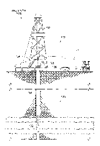
[0004] FIG. lA is a diagram of an example well system.
[0005] FIG. 1B is a diagram of an example well system that includes a
resistivity logging
tool in a wireline logging environment.
[0006] FIG. 1C is a diagram of an example well system that includes a
resistivity logging
tool in a logging while drilling (LWD) environment.
[0007] FIG. 2 is a diagram of an example computing system.
[0008] FIG. 3 is a diagram of an example resistivity logging tool.
[0009] FIG. 4 is a diagram of an example formation model.
1
CA 02861665 2015-03-04
[00101 FIG. 5 is a diagram of example coordinate systems.
100111 FIG. 6 is a diagram of example coordinate systems.
[0012] FIG. 7 is a diagram showing example resistivity logging angle bins.
[0013] FIG. 8 is a screenshot that includes plots showing example simulated
resistivity
logging data.
[0014] FIG. 9 is a diagram of an example technique for detecting subsurface
layer
boundaries based on resistivity logging data.
100151 FIG. 10 is a flowchart showing an example technique for identifying
subsurface
layer boundaries.
[0016] Like reference symbols in the various drawings indicate like elements.
DETAILED DESCRIPTION
[0017] FIG. IA is a diagram of an example well system 100. The example well
system
100 includes a resistivity logging system 108 and a subterranean region 120
beneath the
ground surface 106. A well system can include additional or different features
that are not
shown in FIG. 1A. For example, the well system 100 may include additional
drilling
system components, wireline logging system components, etc.
[00181 The subterranean region 120 can include all or part of one or more
subterranean
formations or zones. The example subterranean region 120 shown in FIG. lA
includes
multiple subsurface layers 122 and a wellbore 104 penetrated through the
subsurface
layers 122. The subsurface layers 122 can include sedimentary layers, rock
layers, sand
layers, or combinations of these other types of subsurface layers. One or more
of the
subsurface layers can contain fluids, such as brine, oil, gas, etc. Although
the example
wellbore 104 shown in FIG. IA is a vertical wellbore, the resistivity logging
system 108
can be implemented in other wellbore orientations. For example, the
resistivity logging
system 108 may be adapted for horizontal wellbores, slant wellbores, curved
wellbores,
vertical wellbores, or combinations of these.
[0019] The example resistivity logging system 108 includes a logging tool 102,
surface
equipment 112, and a computing subsystem 110. In the example shown in FIG. 1A,
the
logging tool 102 is a downhole logging tool that operates while disposed in
the wellbore
104. The example surface equipment 112 shown in FIG. 1A operates
2
CA 02861665 2014-06-16
at or above the surface 106, for example, near the well head 105, to control
the
logging tool 102 and possibly other downhole equipment or other components of
the
well system 100. The example computing subsystem 110 can receive and analyze
logging data from the logging tool 102. A resistivity logging system can
include
additional or different features, and the features of a resistivity logging
system can be
arranged and operated as represented in FIG. lA or in another manner.
[0020] In some instances, all or part of the computing subsystem 110 can be
implemented as a component of, or can be integrated with one or more
components
of, the surface equipment 112, the logging tool 102 or both. In some cases,
the
computing subsystem 110 can be implemented as one or more discrete computing
system structures separate from the surface equipment 112 and the logging tool
102.
The computing subsystem 110 can be or include the example computing system 200
shown in FIG. 2, other types of computing apparatus, or a combination of them.
[0021] In some implementations, the computing subsystem 110 is embedded in the
logging tool 102, and the computing subsystem 110 and the logging tool 102 can
operate concurrently while disposed in the wellbore 104. For example, although
the
computing subsystem 110 is shown above the surface 106 in the example shown in
FIG. 1A, all or part of the computing subsystem 110 may reside below the
surface
106, for example, at or near the location of the logging tool 102.
[0022] The well system 100 can include communication or telemetry equipment
that
allow communication among the computing subsystem 110, the logging tool 102,
and
other components of the resistivity logging system 108. For example, the
components
of the resistivity logging system 108 can each include one or more
transceivers or
similar apparatus for wired or wireless data communication among the various
components. For example, the resistivity logging system 108 can include
systems and
apparatus for wireline telemetry, wired pipe telemetry, mud pulse telemetry,
acoustic
telemetry, electromagnetic telemetry, or a combination of these other types of
telemetry. In some cases, the logging tool 102 receives commands, status
signals, or
other types of information from the computing subsystem 110 or another source.
In
some cases, the computing subsystem 110 receives logging data, status signals,
or
other types of information from the logging tool 102 or another source.
3
CA 02861665 2014-06-16
[00231 Resistivity logging operations can be performed in connection with
various
types of downhole operations at various stages in the lifetime of a well
system. Many
of the structural attributes and components of the surface equipment 112 and
logging
tool 102 will depend on the context of the resistivity logging operations. For
example,
resistivity logging may be performed during drilling operations, during
wireline
logging operations, or in other contexts. As such, the surface equipment 112
and the
logging tool 102 may include, or may operate in connection with drilling
equipment,
wireline logging equipment, or other equipment for other types of operations.
100241 In some examples, resistivity logging operations are performed during
wireline logging operations. FIG. 1B shows an example well system 100b that
includes the resistivity logging tool 102 in a wireline logging environment.
In some
example wireline logging operations, a the surface equipment 112 includes a
platform
above the surface 106 is equipped with a derrick 132 that supports a wireline
cable
134 that extends into the wellbore 104. Wireline logging operations can be
performed,
for example, after a drilling string is removed from the wellbore 104, to
allow a the
wireline logging tool 102 to be lowered by wireline or logging cable into the
wellbore
104.
100251 In some examples, resistivity logging operations are performed during
drilling
operations. FIG. 1C shows an example well system 100c that includes the
resistivity
logging tool 102 in a logging while drilling (LWD) environment. Drilling is
commonly carried out using a string of drill pipes connected together to form
a drill
string 140 that is lowered through a rotary table into the wellbore 104. In
some cases,
a drilling rig 142 at the surface 106 supports the drill string 140, as the
drill string 140
is operated to drill a wellbore penetrating the subterranean region 120. The
drill string
may include, for example, a kelly, drill pipe, a bottom hole assembly, and
other
components. The bottom hole assembly on the drill string may include drill
collars,
drill bits, the logging tool 102, and other components. The logging tools may
include
measuring while drilling (MWD) tools, LWD tools, and others.
[0026] In some example implementations, the logging tool 102 includes a
formation
resistivity tool for obtaining resistivity measurements from the subterranean
region
120. As shown, for example, in FIG. 1B, the logging tool 102 can be suspended
in the
wellbore 104 by a wireline cable, coiled tubing, or another structure that
connects the
tool to a surface control unit or other components of the surface equipment
112. In
4
CA 02861665 2014-06-16
some example implementations, the logging tool 102 is lowered to the bottom of
a
region of interest and subsequently pulled upward (e.g., at a substantially
constant
speed) through the region of interest. As shown, for example, in FIG. 1C, the
logging
tool 102 can be deployed in the wellbore 104 on jointed drill pipe, hard wired
drill
pipe, or other deployment hardware. In some example implementations, the
logging
tool 102 collects data during drilling operations as it moves downward through
the
region of interest during drilling operations.
100271 In some example implementations, the logging tool 102 collects data at
discrete logging points in the wellbore 104. For example, the logging tool 102
can
move upward or downward incrementally to each logging point at a series of
depths
in the wellbore 104. At each logging point, instruments in the logging tool
102 (e.g.,
the transmitters and receivers shown in FIG. 3) perform measurements on the
subterranean region 120. The measurement data can be communicated to the
computing subsystem 110 for storage, processing, and analysis. Such formation
evaluation data may be gathered and analyzed during drilling operations (e.g.,
during
logging while drilling (LWD) operations), during wireline logging operations,
or
during other types of activities.
[0028] The computing subsystem 110 can receive and analyze the measurement
data
from the logging tool 102 to detect the subsurface layers 122. For example,
the
computing subsystem 110 can identify the boundary locations and other
properties of
the subsurface layers 122 based on the resistivity measurements acquired by
the
logging tool 102 in the wellbore 104. For example, in some cases, higher
resistivity
indicates a higher possibility of hydrocarbon accumulation.
[0029] In some cases, the boundary locations of the subsurface layers 122 are
detected based on a distance to bed boundary (DTBB) analysis. For example, the
resistivity logging system 108 may determine the distance to the boundary of
each
subsurface layer 122 from a reference point on the logging tool 102. The
reference
point on the logging tool 102 can represent, for example, the wellbore depth
at or near
the axial center of an array of transmitters and receivers in the logging tool
102, or the
wellbore depth at another location. The boundary of each subsurface layer 122
can
represent, for example, the wellbore depth where the subsurface layers 122
intersect
the wellbore 104.
CA 02861665 2014-06-16
100301 In some implementations, the logging tool 102 includes multiple
antennas that
each operate as a transmitter or a receiver. The transmitter antennas can
employ
alternating currents to generate an electromagnetic field, which can induce
eddy
current in the surrounding region. The eddy current can generate a magnetic
field that
can be detected by the receiver antennas in the logging tool 102.
100311 Some example logging tools include multiple transmitters and multiple
receivers, with each transmitter and each receiver at a different position
along the
longitudinal axis of the logging tool. Multiple receivers can detect a
response based
on the signal from a single transmitter. The signal received by two spaced-
apart
receivers can have a phase and amplitude difference.
[0032] In some instances, some or all of the transmitters and receivers in a
single
logging tool can operate at multiple electromagnetic frequencies. Measurements
obtained by transmitters and receivers operated at multiple frequencies and
multiple
spacings can provide versatility and other advantages in formation detection.
The
sensitivity range may be affected by the formation, the tool's structure, or
other
considerations.
100331 Various aspects of the subterranean region 120 can affect the
resistivity
measurements generated by the logging tool 102. For example, formation
anisotropy,
formation dip angle, distances to boundary, and other factors may have
significant
effects on resistive logging measurements, and the resistivity logging system
108 can
account for these parameters to obtain accurate formation resistivity and
position
estimation.
100341 In some instances, the example computing subsystem 110 uses an
inversion
technique to obtain information on the formation parameters based on the
resistivity
measurement data generated by the logging tool 102. Some example inversion
techniques operate by searching for an optimum or otherwise acceptable match
between simulated data and measurements. The simulated data can be generated
with
assumptions of formation parameters, including horizontal resistivity,
vertical
resistivity, dip angle, boundary position, etc.
100351 In some cases, the example resistivity logging system 108 can generate
fast,
real-time distance to boundary calculations. For example, in the drilling
context, the
location of a current logging point can be important for making on-site
drilling
6
CA 02861665 2014-06-16
decisions. When the formation resistivity is known, one-dimensional (1D)
inversion
code can obtain the distance to bed boundaries (DTBB) with directional LWD
measurements and can give the inversion result when enough measurements are
available.
[0036] For some example inversion techniques, two unknown distances (e.g., the
distances to upper and lower boundaries) can be determined from at least two
different raw measurements from the logging tool 102. For example, the two raw
measurements may be needed to reduce uncertainty. In some instances, the
logging
tool 102 obtains two or more raw measurements at a single logging location in
the
wellbore 104, and transmits all of the raw measurements to the computing
subsystem
110 for analysis (e.g., for distance to bed boundary calculations).
[0037] An inversion technique can identify boundaries of multiple adjacent
subsurface layers based on data obtained at a single tool depth. Such one-
dimensional
inversion techniques can be used to identify subterranean formation parameters
based
on measurements generated by a directional resistivity instrument. Such one-
point
inversion techniques can operate based on inputs that include multi-spacing
and
multi-frequency measurements generated by the directional resistivity
instrument.
[0038] In some example implementations, an iterative algorithm can generate
the
multi-layer formation profile from data acquired at a single logging point.
Each
iteration can use different sensitivity range measurements. The inversion can
start
with a simple model of few layers, for example, to reduce the complexity, to
reduce
computing time, to increase the accuracy, or to achieve any combination of
these and
other advantages. Boundaries within the first layers can be identified from
the shortest
sensitivity range measurements. Other layers can be added by using
increasingly
longer sensitivity range measurements to invert increasingly farther target
layers. A
correction processing can be applied to the inverted result (e.g., after each
inversion
step or at other instances), for example, to eliminate artifacts (e.g., a
"fake layer"
effect).
[0039] FIG. 2 is a diagram of the example computing system 200. The example
computing system 200 can be used as the computing subsystem 110 of FIG. IA, or
the example computing system 200 can be used in another manner. In some cases,
the
example computing system 200 can operate in connection with a well system
(e.g.,
7
CA 02861665 2014-06-16
the well system 100 shown in FIG. 1A) and be located at or near one or more
wells of
a well system or at a remote location. All or part of the computing system 200
may
operate independent of a well system.
[0040] The example computing system 200 shown in FIG. 2 includes a memory 150,
a processor 160, and input/output controllers 170 communicably coupled by a
bus
165. The memory 150 can include, for example, a random access memory (RAM), a
storage device (e.g., a writable read-only memory (ROM) or others), a hard
disk, or
another type of storage medium. The computing subsystem 110 can be
preprogrammed or it can be programmed (and reprogrammed) by loading a program
from another source (e.g., from a CD-ROM, from another computer device through
a
data network, or in another manner).
[0041] In some examples, the input/output controller 170 is coupled to
input/output
devices (e.g., a monitor 175, a mouse, a keyboard, or other input/output
devices) and
to a communication link 180. The input/output devices receive and transmit
data in
analog or digital form over communication links such as a serial link, a
wireless link
(e.g., infrared, radio frequency, or others), a parallel link, or another type
of link.
[0042] The communication link 180 can include any type of communication
channel,
connector, data communication network, or other link. For example, the
communication link 180 can include a wireless or a wired network, a Local Area
Network (LAN), a Wide Area Network (WAN), a private network, a public network
(such as the Internet), a WiFi network, a network that includes a satellite
link, or
another type of data communication network.
[0043] The memory 150 can store instructions (e.g., computer code) associated
with
an operating system, computer applications, and other resources. The memory
150
can also store application data and data objects that can be interpreted by
one or more
applications or virtual machines running on the computing system 200. As shown
in
FIG. 2, the example memory 150 includes logging data 151, layer data 152,
other data
153, and applications 154. The data and applications in the memory 150 can be
stored
in any suitable form or format.
[0044] The logging data 151 can include measurements and other data from a
logging
tool. In some cases, the logging data 151 include one or more measurements for
each
of multiple different logging points in a wellbore. For example, the logging
point
8
CA 02861665 2014-06-16
associated with a given measurement can be the location of the logging tool's
reference point when the given measurement was acquired. Each measurement can
include data obtained by one or more transmitter-receiver pairs operating at
one or
more signal frequencies. Each measurement can include data obtained by
multiple
transmitter-receiver pairs operating at one or more transmitter-receiver
spacings. The
logging data 151 can include information identifying a transmitter-receiver
spacing
associate with each measurement.
[0045] The layer data 152 can include information on subsurface layers. For
example,
the layer data 152 can include information describing the resistivity, size,
depth,
volume, geometry, areal extent, porosity, pressure, and other information on a
subsurface layer. In some implementations, the layer data 152 includes
information
generated by an inversion engine. For example, the layer data 152 may include
distance to bed boundary information derived from resistivity measurements and
other
information in the logging data 151. Accordingly, the layer data 152 may
include
information associated with one or more logging points. For example, the layer
data
152 may indicate the distance from a logging point to one or more layer
boundaries.
[0046] The other data 153 can include other information that is used by,
generated by,
or otherwise associated with the applications 154. For example, the other data
153 can
include simulated data or other information that can be used by an inversion
engine to
produce the layer data 152 from the logging data 151.
[0047] The applications 154 can include software applications, scripts,
programs,
functions, executables, or other modules that are interpreted or executed by
the
processor 160. For example, the applications 154 can include an inversion
engine and
other types of modules. The applications 154 may include machine-readable
instructions for performing one or more of the operations related to FIGS. 8-
10.
[0048] The applications 154 can obtain input data, such as logging data,
simulation
data, or other types of input data, from the memory 150, from another local
source, or
from one or more remote sources (e.g., via the communication link 180). The
applications 154 can generate output data and store the output data in the
memory
150, in another local medium, or in one or more remote devices (e.g., by
sending the
output data via the communication link 180).
9
CA 02861665 2014-06-16
100491 The processor 160 can execute instructions, for example, to generate
output
data based on data inputs. For example, the processor 160 can run the
applications
154 by executing or interpreting the software, scripts, programs, functions,
executables, or other modules contained in the applications 154. The processor
160
may perform one or more of the operations related to FIGS. 8-10. The input
data
received by the processor 160 or the output data generated by the processor
160 can
include any of the logging data 151, the layer data 152, or the other data
153.
100501 FIG. 3 is a diagram of an example resistivity logging tool 300. The
example
resistivity logging tool 300 can be used in the resistivity logging system 108
shown in
FIG. IA, for example, as the logging tool 102, as a component of the logging
tool 102
or in another manner. The example resistivity logging tool 300 can be used in
other
types of systems (including other types of resistivity logging systems) or in
other
contexts (e.g., in other types of well systems).
[00511 Generally, a directional resistivity tool has a number (N) of tilted or
coaxial
transmitter antennas 771, T2, T3, ..., TN spaced along the tool, and a number
(N') of
tilted or coaxial receiver antennas R1, R2, R3, R NI that are axially
spaced apart
from the transmitter antennas and from each other. In some instances, after
the
resistivity logging tool has been placed in a wellbore, the tool can rotate
and collect
receiver measurements excited by multi-spacing and multi-frequency current
source
transmitters. Measurements acquired by a directional resistivity tool at
different
frequencies and spacings may have different sensitivities to formation
parameters and
different detection ability, even for the same parameter. In some instances,
long
transmitter/receiver spacings perform deep measurements for bed boundary and
shoulder resistivity, while short transmitter/receiver spacings provide
accurate
information of a local area.
100521 The example resistivity logging tool 300 is one example of a
directional
resistivity tool. The example resistivity logging tool 300 includes a tool
body 303, six
transmitters 302a, 302b, 302c, 302d, 302e, 302f and three receivers 304a,
304b, 304c.
A resistivity logging tool can include additional features, such as, for
example, data
processing apparatus to control operation of the transmitters and receivers, a
power
supply to power the transmitters and receivers, a computing subsystem to
process data
from the transmitters and receivers, a telemetry system for communicating with
external systems, etc. A resistivity logging tool can include a different
number of
CA 02861665 2014-06-16
transmitters, a different number of receivers, or both, and the transmitters
and
receivers can be arranged as shown in FIG. 3 or in another type of
arrangement.
100531 The tool body 303 can include structures, components, or assemblies to
support the transmitters, receivers, and possibly other components of the
resistivity
logging tool 300. The tool body 303 can be connected to other components of a
resistivity logging system, such as, for example, a drilling assembly, a
wireline
assembly, or another type of component. The example tool body 303 shown in
FIG. 3
defines a longitudinal axis of the resistivity logging tool 300, and each
transmitter or
receiver is fixed at a different position along the longitudinal axis.
[0054] During operation, the tool body 303 can be moved within a wellbore
through a
series of logging points. At each logging point, some or all of the
transmitters and
receivers can be operated at one or more signal frequencies to collect
resistivity data,
which can be processed at the resistivity logging tool 300, transmitted to
another
system for processing, or both.
[0055] In the discussion that follows, the transmitters 302a, 302b, 302c,
302d, 302e,
and 302f are referred to as T1, T2, T3, T3I, T2, , and T1,, respectively, and
the receivers
304a, 304b, and 304c are referred to as R1, R2, and R3, respectively.
Generally, the
transmitter elements and receiver elements can be disposed at any angle with
respect
to the longitudinal axis of the resistivity logging tool 300. In the example
shown in
FIG. 3, the transmitters T1, T2, T3, T31, T21, and T1, are each coaxial with
the
longitudinal axis, and the receiver elements R1, R2, and R3 are tilted at an
angle of 45
degrees with respect to the longitudinal axis. In some cases, the transmitters
can be
tilted and the receivers can be coaxial; and in some cases, the transmitters
and
receivers are all tilted, and the transmitter and receiver tilt angles can be
the same or
they can be different. In addition, the roles of transmitters and receivers
may be
interchanged. Transmitter elements and receiver elements in other
configurations can
be used.
[0056] The spacing of the antennas along the longitudinal axis may be stated
in terms
of a length parameter x. In some implementations of the example resistivity
logging
tool 300, the length parameter x is equal to 16 inches; another value of the
length
parameter may be used. In the example shown in FIG. 3, measuring along the
longitudinal axis from a midpoint between the centers of receiver antennas R1
and R2,
CA 02861665 2014-06-16
transmitters T3 and T3, are located at + lx (e.g., + 16 inches), transmitters
T2 and T2/
are located at +2x (e.g., + 32 inches), and transmitters T1 and T1, are
located at +3x
(e.g., + 48 inches); the receiver antennas R1 and R2 are located at +x/4
(e.g., + 4
inches), and the receiver antenna R3 is located at ¨4x (e.g.,- 64 inches). The
transmitters and receivers may be placed at different locations.
[0057] The length parameter and spacing coefficients may be varied as desired
to
provide greater or lesser depth of investigation, higher spatial resolution,
or higher
signal to noise ratio. With the illustrated spacing, symmetric resistivity
measurements
can be made with lx, 2x, and 3x spacing between the tilted receiver antenna
pair
R1 ¨ R2, and the respective transmitters in each of the equally-spaced pairs
T1 ¨ Te;
T2 ¨ T2'; T3 ¨ T31. In addition, asymmetric resistivity measurements can be
made
with lx, 2x, 3x, 5x, 6x, and 7x spacing between the tilted receiver antenna R3
and
the respective transmitters T1, T2, T3, T3/, T2/, and T1i. In some cases, this
spacing
configuration provides versatility, enabling deep (but asymmetric)
measurements for
bed boundary detection and symmetric measurements for accurate azimuthal
resistivity determination.
[0058] In some aspects of operation, each of the six transmitters T1, T2, T3,
T3/, T2/,
and T1, can be energized in turn, and the phase and amplitude of the resulting
voltage
induced in each of the three receiver coils R1, R2, and R3 can be measured.
Measurement over a full rotation (360 degrees of rotation) can be acquired
while the
tool rotates at a given logging position in the wellbore. The measurements
distributed
over 360 degrees can be divided into M bins, where each bin covers an angle of
360/M degrees. The first bin ("binl") can represent the measurement in the
upper
right direction, perpendicular to the longitudinal axis of the logging tool.
As an
example, if the total number of bin is 32, then the seventeenth bin ("bin17")
is the
reverse (opposite) direction of "binl ." From these measurements, or a
combination of
these measurements, the formation resistivity can be determined.
[0059] In some implementations, because the response of the tilted antennas is
azimuthally sensitive, the geosignal calculated for a bin can be used as a bed
boundary indicator. An example geosignal calculation function takes the
difference
between phase or log amplitude for the current bin and the average phase or
log
amplitude for all the bins at a given axial position in the wellbore:
12
CA 02861665 2014-06-16
geo_attruTi(k) = 20 log(ARITI(k)) ¨ ¨
32 ¨i.L..3220 logARITI(i)
(1)
,
geO_phaRITI (k) = T1(k) ¨ Li=1...32 ORIT1(i)
(2)
In Equations (1) and (2) above, "geo" indicates a geosignal, "att" indicates
attenuation, "pha" indicates phase, "A" indicates amplitude of voltage, "0"
indicates
phase of voltage, "R" indicates the receiver and "T" indicates transmitter.
For
example, geo_attRun (k) indicates the geosignal attenuation of the kth bin
measurement on receiver R1 excited by T1 and geo_phaRm (k) indicates the
geosignal phase of the kth bin measurement on receiver R1 excited by T1.
Values of
geo_pha are represented in units of degrees and values of geo_att are
represented in
units decibel (dB).
100601 Equations (1) and (2) above show example geosignal calculations, which
generate a resistivity logging measurement based on data acquired by operating
one
transmitter and receiver pair. Other types of equations can be used to
generate a
resistivity logging measurement, and a resistivity logging measurement can be
generated based on data acquired by operating one transmitter and receiver
pair, or
based on data acquired by operating multiple transmitter and receiver pairs.
100611 For example, a compensated resistivity logging measurement can be
generated
by averaging (or otherwise combining) data acquired by multiple symmetric
transmitter-receiver pairs. The transmitter and receiver pairs can include a
single
transmitter and multiple receivers, a single receiver and multiple
transmitters, or
multiple transmitters and multiple receivers. Each transmitter and receiver
pair used to
generate a resistivity logging measurement can have the same transmitter-
receiver
spacing, or data from multiple transmitter-receiver spacings may be used to
generate a
resistivity logging measurement. An example of a compensated amplitude
measurement a, is provided as follows:
an = log(AR21) log(All) (3a)
an' = log(Anin') 102(A
R2T1') (3b)
ac = (an i + a1')/2 (3c)
13
CA 02861665 2014-06-16
Other types of compensated or uncompensated resistivity logging measurements
can
be generated based on data acquired by operating one or more transmitter-
receiver
pairs of a resistivity logging tool.
[0062] In some implementations, measurements from the example resistivity
logging
tool 300 shown in FIG. 3 can include measurements associated with transmitter-
receiver (T-R) spacings of 16 inches, 32 inches, 48 inches, 80 inches, 96
inches and
112 inches. The azimuthal orientation of the tool can be measured from the top
of the
wellbore or it can be calculated from measured data. With the known azimuthal
angle,
curve shifting can be used to provide the logging measurement at an azimuth of
zero.
As such, various aspects of this discussion assume a known azimuthal
orientation, but
the discussion can be adapted for other scenarios.
[0063] In some implementations, one or more geosignals are generated at the
resistivity logging tool 300 (e.g., by one or more processors on the
resistivity logging
tool 300) based on the signals acquired by the transmitters and receivers, or
the
geosignals can be generated external to the resistivity logging tool 300. A
computing
system (e.g., the computing subsystem 110 in FIG. 1A) can access the generated
geosignals and perform the distance to bed boundary calculation based on the
geosignals. For example, the computing system may perform an inversion method
that is configured to receive multiple geosignals as inputs. The inversion
method may
identify the locations of one or more subsurface layer boundaries and other
properties
of a subterranean region.
[0064] FIG. 4 is a diagram of an example subterranean formation model 400 used
for
numerical simulations. The example subterranean formation model 400 includes a
layered formation in a subterranean region 408 and a coordinate axis 410 that
represents the longitudinal axis of the resistivity logging tool (e.g., the z-
axis in FIG.
6). In the subterranean region 408 shown in FIG. 4, the formation layers each
define a
dip angle with respect to the coordinate axis 410. The dip angle can be, for
example,
eighty degrees or another value.
[00651 The example subterranean formation model 400 includes five subsurface
layers 412a, 412b, 412c, 412d, 412e, where each subsurface layer is adjacent
to, and
shares a boundary with, one or two neighboring subsurface layers. The middle
subsurface layer 412c is adjacent to, and shares a boundary with, neighboring
14
CA 02861665 2014-06-16
subsurface layers 412b, 412d; subsurface layer 412b is adjacent to, and shares
a
boundary with, neighboring subsurface layers 412a, 412c; subsurface layer 412d
is
adjacent to, and shares a boundary with, neighboring subsurface layers 412c,
412e.
[0066] The example diagram shown in FIG. 4 shows the locations of two
transmitter
antennas 402a, 402b and a receiver antenna 404 along the longitudinal axis of
the
resistivity logging tool. The distance between the first transmitter antenna
402a and
the receiver 404 defines a first transmitter-receiver spacing; and the
distance between
the second transmitter antenna 402b and the receiver 404 defines a second,
shorter
transmitter-receiver spacing.
[0067] FIG. 4 shows the sensitivity ranges of the example transmitter-receiver
pairs
for an example mode of operation (e.g., at an example operating frequency,
etc.). The
first transmitter-receiver pair (transmitter antenna 402a and receiver antenna
404)
have the longer transmitter-receiver spacing, and therefore the longer
sensitivity range
represented by the point 422a on the axis 420a. The second transmitter-
receiver pair
(transmitter antenna 402b and receiver antenna 404) have the shorter
transmitter-
receiver spacing, and therefore the shorter sensitivity range represented by
the point
422b on the axis 420b.
[0068] As shown in FIG. 4, the respective near and far layers can give a
stronger or
weaker effect on the same measurement. For example, the sensitivity range of
the
second transmitter-receiver pair extends into the near layer 412d, and the
near layer
412d has a stronger effect on the measurement associated with the shorter
transmitter-
receiver spacing; and the sensitivity range of the first transmitter-receiver
pair extends
into the far layer 412e, and the far layer 412e has a stronger effect on the
measurement associated with the longer transmitter-receiver spacing. In some
cases,
the far layer 412e may have an insubstantial effect on the measurement
associated
with the shorter transmitter-receiver spacing.
[0069] An inversion technique, such as, for example, the inversion techniques
represented in FIGS. 9 and 10, can account for the different sensitivity
ranges of the
different transmitter-receiver spacings. For example, the inversion technique
can
detect the boundary locations of the near layer 412d from measurements
generated
based on operating the second transmitter-receiver pair (transmitter antenna
402b and
receiver antenna 404) that has the shorter transmitter-receiver spacing; and
the
CA 02861665 2014-06-16
inversion technique can detect the boundary locations of the far layer 412e
from
measurements generated based on operating the first transmitter-receiver pair
(transmitter antenna 402a and receiver antenna 404) that has the longer
transmitter-
receiver spacing. Accordingly, based on the different sensitivity ranges,
measurements associated with the different transmitter-receiver spacings can
be used
to separately identify subsurface layers at different depths.
[0070] FIG. 5 is a diagram of an example coordinate system 500. In particular,
FIG. 5
shows a schematic perspective view of a Cartesian coordinate system of a
sedimentary earth formation. In some cases, the subsurface layers (e.g.,
layers formed
by sedimentary buildup, or other types of layers) are not perpendicular to the
wellbore
of the well system. For example, the wellbore 104 in FIG. 1A could be drilled
at an
angle with respect to a normal of the subsurface layers 122. The angle can be
a result
of directional drilling, a natural dip or strike angle of the subsurface
layers, or a
combination of these and other factors.
[0071] In some implementations, when measuring formation resistivity and
orientation, it is convenient to use the formation coordinate system 500 shown
in FIG.
5. Other coordinate systems may also be used. FIG. 5 shows a portion of a
sedimentary formation bed, with the z-axis oriented perpendicular to the plane
of the
formation, in the direction of the sedimentary accretion. In a dipping bed,
the x-axis
can be chosen to be oriented in the direction of deepest descent (i.e.,
"downhill"), or
another orientation can be chosen.
[0072] The horizontal resistivity (which may be represented by Rx, Ry, or a
combination of them) is the resistivity in a direction of x-y plane, and the
vertical
resistivity (Rz) is the resistivity in z-axis direction. In an electrically
isotropic
formation, the horizontal resistivity and vertical resistivity are equal,
while in an
electrically anisotropic formation, the horizontal and vertical resistivity
can be
different.
[0073] FIG. 6 is a diagram showing relationships between coordinate systems.
In
particular, FIG. 6 shows the relationship between the coordinate system of a
wellbore
and the coordinate system of a dipping formation bed (e.g., the formation
coordinate
system 500 shown in FIG. 5). In the example shown in FIG. 6, the x-, y-, and z-
axes
define the coordinate system of the wellbore, and the x"-, y"-, and z"-axes
represent
16
CA 02861665 2014-06-16
the formation coordinate system. The z-axis of the wellbore coordinate system
is
aligned with the wellbore's long axis, and the x-axis of the wellbore
coordinate
system can be directed to the north side of the wellbore, the high side of the
wellbore,
or another direction. In some cases, the longitudinal axis of the resistivity
logging tool
lies in a plane having an azimuthal angle with respect to the tool face scribe
line.
[0074] In the example shown in FIG. 6, the two coordinate systems (x, y, z)
and (x",
y", z") are related by two rotations. Beginning with the wellbore system (x,
y, z), a
first rotation of angle y is made about the z-axis. The resulting coordinate
system is
denoted (x', y', z') in FIG. 6. Angle y can be a relative strike angle that
indicates the
direction of the formation dip relative to the wellbore's coordinate system. A
second
rotation of angle 8 is then made about the y'-axis to arrive at the formation
coordinate
system, which is denoted (x", y", z") in FIG. 6. This aligns the formation
coordinate
system with the vvellbore coordinate system. The angle 8 can be a relative dip
angle
that indicates the angle between the longitudinal axis of the resistivity
logging tool
and the normal of the formation beds.
[0075] FIG. 7 is a diagram showing example resistivity logging angle bins in a
coordinate plane 700. A resistivity logging tool can generate measurements for
a full
range of azimuthal angles (e.g., 360 degrees of rotation) by rotating the tool
about its
longitudinal axis at a given logging position in the wellbore. The
measurements can
be divided into N bins, where each bin covers an angle of 360/N degrees. In
the
example shown in FIG. 7, the first bin is represented as 13i, the second bin
is
represented as 132, etc. The boundary locations for subsurface layers can be
identified
from the data corresponding to a single bin or a combination of multiple bins.
[0076] FIG. 8 is a screenshot 800 that includes three plots 810, 820, 830
showing
example simulated resistivity logging data. The horizontal axis in each of the
plots
810, 820, 830 represents a range of departure in a three layer formation, in
the
wellbore coordinate system. The curve 812 in the first plot 810 shows the
relationship
between the coordinate systems represented in FIG 6; the vertical axis in the
first plot
810 represents the true vertical depth (TVD) in the three layer formation, in
the
formation coordinate system. The shading of the background of the first plot
810
shows the locations of three subsurface layers that were used to simulate the
data
represented in FIG. 8. The middle subsurface layer (which ranges from 510 feet
to
17
CA 02861665 2014-06-16
530 feet) is modeled with a resistivity of 20 ohms; the upper and lower layers
(on
either side of the middle layer) are each modeled with a resistivity of 5
ohms.
[0077] The second plot 820 shows resistivity versus departure based on
simulated
resistivity logging measurements associated with three different transmitter-
receiver
(T-R) spacings at a working frequency of 500 kHz. The first curve 822 shows
the
resistivity based on a measurement from a 48-inch T-R spacing, the second
curve 824
shows the resistivity based on measurements from a 32-inch T-R spacing, and
the
third curve 826 shows the resistivity based on measurements from a 16-inch T-R
spacing.
[0078] The third plot 830 shows the measured geosignal versus departure based
on
simulated resistivity logging measurements for each of the three transmitter-
receiver
(T-R) spacings at a working frequency of 500 kHz. The first curve 832 shows
the
measured geosignal for the 48-inch T-R spacing, the second curve 834 shows the
measured geosignal for the 32-inch T-R spacing, and the third curve 836 shows
the
geosignal associated for 16-inch T-R spacing.
[0079] As shown in the second and third plots 820, 830, the resistivity and
geosignal
from the 48-inch T-R spacing has a deeper detection range, while the
resistivity and
geosignal from the 16-inch T-R spacing has a shorter detection range. These
different
sensitivity ranges can be used to determine boundary locations and other
properties of
subsurface layers at different depths. For example, the longer T-R spacing can
be used
to detect properties of subsurface layers farther from the resistivity logging
tool, and
the shorter T-R spacing can be used to detect properties of subsurface layers
closer to
the resistivity logging tool.
[0080] FIG. 9 is a diagram 900 of an example technique for detecting
subsurface
layer boundaries based on resistivity logging data. The diagram 900 in FIG. 9
shows a
series of layers 910, measurements 920, and boundaries 930. In the diagram
900, the
individual layers are labeled R(-n), R(-2), R(-1), R(0), R(1),
R(2), R(n); the
individual measurements are labeled M(1), M(2), M(n); and the individual
boundaries are labeled D(-n), D(-3), D(-2),
D(-1), D(1), D(2), D(3), D(n). As an
example, the layers 910 can represent the subsurface layers 122 shown in FIG.
1A, or
other subsurface layers.
18
CA 02861665 2014-06-16
[0081] Each of the example measurements 920 is associated with a different
transmitter-receiver (T-R) spacing. The measurement labels are ordered from
the
shortest T-R separation M(1) to the longest T-R separation M(n). In the
example
shown, M(1) is the measurement from a 16-inch T-R spacing, M(2) is the
measurement from a 32-inch T-R spacing; and M(n) is the measurement from a 112-
inch T-R spacing.
[0082] An example inversion technique based on the measurements M(1), M(2),
...
M(n) can proceed in an iterative fashion. For example, a first three layer
inversion can
identify the boundaries D(-1), D(1) for the three middle layers R(-1), R(0),
R(1) from
the measurement M(1). The next two layers R(-2), R(2) are then added to the
model;
and the boundaries D(-2), D(2) for these layers are identified from the
measurement
M(2). This process can continue iteratively, for example, until all
measurements have
been used or until another criteria is met. In the example shown in FIG. 9,
the
boundaries D(-n), D(n) for the last two layers R(-n). R(n) are identified from
the
measurement M(n).
[0083] In this manner, as shown by the example represented in FIG. 9, each
layer's
effect on measurements from different T-R spacings are separated by using each
measurement to invert a target influence layer. Such inversion techniques can,
in
some instances, provide more accurate output and require less computing time
than
some conventional techniques that perform a multiple layer inversion from all
measurements together.
[0084] In the inversion technique represented in FIG. 9 and related
techniques, the
signal used for an inversion can be chosen based on the structure and
frequency of the
measurement, for example, to avoid the formation resistivity input or based on
other
factors. In some examples, full logging data for different spacings and
frequencies are
measured at one logging point (i.e., at one tool depth in the wellbore). All
measurements from the same transmitter-receiver pair can be set in the same
group,
and the signals in a single group can have different working frequencies.
[0085] In some examples, the first three layer inversion (e.g., layers R(-1),
R(0), R(1))
can be processed with the measurements of shortest T-R spacing. If the signals
do not
provide enough information to invert the unknown parameters of the three-layer
portion of the formation, signals associated with the second-shortest T-R
spacing can
19
CA 02861665 2014-06-16
be added into the three layer inversion. The formation with the current
location layer
and two shoulder layers can be plotted with this inversion result.
[0086] In some implementations, after the first three layer inversion, two
more far
layers (e.g., layers R(-2), R(2)) are added in the current inverted formation,
and a
similar inversion procedure can be performed based on the measurements from
the
next-longer T-R pair. As such, on the second inversion, a five-layer formation
can be
inverted with measurements from two T-R spacings. The process can continue,
adding additional layers and inverting based on data from progressively longer
T-R
spacings. This process can continue, for example, in an iterative fashion, to
invert a
deeper formation until all spacing measurements are used.
[0087] An individual inversion can, in some instances, falsely identify a
layer, and
this "fake layer" effect can be accounted for by including checks and
appropriate
corrections in the inversion algorithm. In some cases, the checks can identify
the
falsely-generated layers, and an appropriate correction can be applied to
obtain
accurate formation data. Examples of checks that may be applied to identify
false
layers include checking for very thin layers, checking for layers that have
the same (or
substantially the same) resistivity as a neighboring layer, and others. As
another
example, a false layer can be identified based on its location with respect to
other
layers.
[0088] In some implementations, the inversion algorithm sets a maximum
distance to
the boundary for each sub-inversion. The maximum distance can depend, for
example, on the depth of investigation of the input data under the current
formation
resistivity. For example, in some instances, a measurement spacing associated
with a
weak sensitivity may not produce an accurate inversion result for far
boundaries. For
instance, in some example resistivity logging tools, the maximum distance to
bed
boundary for the 16-inch T-R spacing can be set to 32 inches (or another
value), and
an inverted bed boundary over 32 inches from the 16-inch T-R spacing can be
disregarded, marked as having high uncertainty or untrustworthy, or handled in
another manner. In some instances, such inversions can be used in the limit of
the
detection range.
[0089] In some implementations, when the layer checking operations in the
inversion
algorithm indicate a false layer, neighboring layers can be combined to form a
single
CA 02861665 2014-06-16
subsurface layer (and the false layer can be deleted) that more accurately
represents
the physical formation. For example, a false layer can be generated as a
result of
adding fixed layers for each measurement spacing. Neighboring layers can be
combined to remove a false layer, for example, when the neighboring layers
have
same or similar resistivities or when one of the neighboring layers has an
insubstantial
thickness. To combine the layers, the formation model can be updated with the
new
layer information, and the distance to bed boundary inversion can be
recalculated
based on the new layer information. In some examples, a minimum layer
thickness
can be set based on the vertical resolution of the measurement or other
factors.
[0090] In some implementations, when the layer checking operations in the
inversion
algorithm indicate a false layer, neighboring layers can be reordered or
interchanged.
As an illustration, if the first inverted upper layer is at 5 feet with
resistivity of 5 ohm-
meters and the second inverted upper layer is at 4 feet with resistivity of 10
ohm-
meters, the formation model can be corrected by interchanging the order of the
first
and second layers. Two or more neighboring layers can be combined, reordered,
or
otherwise modified in these and various other instances to improve the
accuracy of
the inversion algorithm output.
[0091] FIG. 10 is a flowchart showing an example process 1000 for identifying
subsurface layer boundaries. Some or all of the operations in the process 1000
can be
implemented by one or more computing devices. For example, the process 1000
can
be implemented by the computing subsystem 110 in FIG. 1A, the computing system
200 in FIG. 2, or by another type of system. Some or all of the operations in
the
process 1000 can be implemented by one or more computing devices that are
embedded with, or otherwise operated in connection with, a logging tool. For
example, the process 1000 can be implemented in connection with the logging
tool
102 in FIG. 1A, the resistivity logging tool 300 in FIG. 3, or another type of
tool.
[0092] In some implementations, the process 1000 may include additional,
fewer, or
different operations performed in the order shown in FIG. 10, or in a
different order.
Moreover, one or more of the individual operations or subsets of the
operations in the
process 1000 can be performed in isolation, or as part of another process.
Output data
generated by the process 1000, including output data generated by intermediate
operations, can include stored, displayed, printed, transmitted, communicated
or
processed information.
21
CA 02861665 2014-06-16
[0093] In some implementations, some or all of the operations in the process
1000 are
executed in real time during a drilling operation or another type of operation
performed in a well system. An operation can be performed in real time, for
example,
by performing the operation in response to receiving data (e.g., from a sensor
or
monitoring system) without substantial delay. An operation can be performed in
real
time, for example, by performing the operation while monitoring for additional
data.
Some real time operations can receive an input and produce an output during
drilling
operations; in some instances, the output is made available within a time
frame that
allows an operator (e.g., a human or machine operator) to respond to the
output, for
example, by modifying the drilling operation.
[0094] In some implementations, a resistivity logging tool can be placed in a
wellbore
defined in a subterranean region that includes multiple subsurface layers. For
example, the resistivity logging tool can be the logging tool 102 shown in
FIG. IA.
The resistivity logging tool can be transported by a drilling assembly, by a
wireline
logging assembly, or other hardware. The resistivity logging tool can be
operated at
multiple tool depths in the wellbore, and each tool depth can represent a
different
logging point. The process 1000 can be used to perform a multi-layer inversion
for the
subterranean region. The process 1000 can be executed based on data for a
single
logging point or multiple logging points. In some cases, the process 1000 can
produce
a reliable, accurate output based on data acquired for a single logging point
in a
complex and discontinuous formation structure.
[0095] At 1002, logging data are acquired from a resistivity logging tool
having
multiple different transmitter-receiver (T-R) spacings. For example, the
logging data
can be acquired by operating transmitters and receivers (which may include
operating
a single transmitter, multiple transmitters, a single receiver, multiple
receivers, or a
combination thereof) of the resistivity logging tool in a wellbore. In some
instances,
the logging data are used to generate a measurement for each T-R spacing. For
example, a first measurement can be generated from the data acquired by
operating
transmitter-receiver pairs associated with a first T-R spacing, and a second
measurement can be generated from the data acquired by operating other
transmitter-
receiver pairs associated with a second T-R spacing.
[0096] The logging data can be acquired a single tool depth (e.g., a single
logging
position) in a wellbore; or in some cases, the logging data can be acquired
from
22
CA 02861665 2014-06-16
multiple tool depths. The measurement for each T-R spacing can be an
individual
value (e.g., a signal attenuation measurement in units of dB, a signal phase
measurement in units of degrees or radians) or multiple values. For example,
resistivity logging measurements can be any of a variety of geosignal types.
Some
examples of resistivity logging measurements are the geosignals calculated
according
to Equations (1), (2), and (3) above; other types of resistivity logging
measurements
can be used. Some examples of simulated measurements are shown in FIG. 8. As
another example, the logging data can be, or they can be used to generate, the
measurements 920 shown in FIG. 9.
[0097] In some instances, each measurement is generated from signals acquired
by
one or more receivers while energizing one or more transmitters. The
measurement
associated with a particular T-R spacing can be based on signals acquired at
one
frequency or at multiple different frequencies. The measurement associated
with a
particular T-R spacing can be based on the signal acquired by a single
receiver while
energizing a single transmitter; the measurement associated with a particular
T-R
spacing can be based on the signals acquired by multiple receivers while
energizing a
single transmitter.
[0098] The T-R spacing associated with a measurement can refer to a distance
along
the longitudinal axis of the resistivity logging tool. For example, the T-R
spacing can
be the distance between the transmitter and receiver that were used to acquire
the
measurement data, or the T-R spacing can be the distance between the
transmitter and
the mid-point between two receivers that were used to acquire the measurement
data.
[0099] For instance, the example resistivity tool 300 shown in FIG. 3 can
generate
measurements associated with six different T-R spacings: lx, 2x, 3x, 5x, 6x,
and 7x.
The measurement associated with the shortest T-R spacing lx can include:
symmetric
resistivity measurements from operating the receiver antenna pair R1 ¨ R2 and
one or
both of the transmitter antenna pair T3 ¨ T3', asymmetric resistivity
measurements
from operating receiver antenna R3 and the transmitter antenna T1,, or both.
The
measurement associated with the second-shortest T-R spacing 2x can include:
symmetric resistivity measurements from operating the receiver antenna pair R1
¨ R2
and one or both of the transmitter antenna pair T2 ¨ T2r, asymmetric
resistivity
measurements from operating receiver antenna R3 and the transmitter antenna
T21, or
23
CA 02861665 2014-06-16
both. The measurement associated with the third-shortest T-R spacing 3x can
include:
symmetric resistivity measurements from operating the receiver antenna pair R1
¨ R2
and one or both of the transmitter antenna pair T1 ¨ Tf, asymmetric
resistivity
measurements from operating receiver antenna R3 and the transmitter antenna
T3f, or
both. The measurement associated with the longest T-R spacing 7x can include
asymmetric resistivity measurements from operating receiver antenna R3 and the
transmitter antenna T1; the measurement associated with the second-longest T-R
spacing 6x can include asymmetric resistivity measurements from operating
receiver
antenna R3 and the transmitter antenna T2; and the measurement associated with
the
third-longest T-R spacing 5x can include asymmetric resistivity measurements
from
operating receiver antenna R3 and the transmitter antenna T3. A resistivity
logging
tool may be capable of generating measurements associated with additional or
different T-R spacings.
[0100] The measurement associated with each T-R spacing can include data
acquired
at one or more operating frequencies. The measurements can be generated based
on a
phase, an amplitude, or a combination of these and other properties of an
electromagnetic signal. In some cases, the resistivity logging tool rotates
about its
longitudinal axis during data acquisition, and the measurements obtained at
1002 can
be based on data acquired at one or more predetermined orientations of the
resistivity
logging tool.
101011 At 1004, a first pair of layer boundaries are identified based on the
logging
data associated with the shortest T-R spacing. For example, the distances from
the
current logging position to the upper and lower layers can be determined from
the first
measurement associated with the first T-R spacing, based on a distance to bed
boundary (DTBB) mapping chart or another analysis tool. Any appropriate
inversion
technique can be used to determine the boundary locations. In some cases, a
DTBB
mapping chart can include known resistivity and dipping angles, and simulated
measurement under different thicknesses and true vertical depths. As an
alternative to
or in addition to using a DTBB mapping chart, the subsurface layer boundaries
can be
determined with a look-up table or an iteration inversion code.
[0102] In some instances, the first pair of layer boundaries are identified
based on the
logging data associated with only the shortest T-R spacing, independent of the
24
CA 02861665 2014-06-16
logging data associated with any other T-R spacing. As an example, the first
pair of
layer boundaries can be the boundaries D(-1), D(1) shown in FIG. 9, and they
can be
identified based on the measurement M(1) and independent of the other
measurements M(2) through M(n).
[0103] In some cases, the first two layer boundaries are the upper and lower
boundaries of a single subsurface layer. For example, the shortest T-R spacing
can be
used to identify the boundary locations of a single subsurface layer, such as,
for
example, the layer that is closest to the longitudinal reference point of the
resistivity
logging tool. In some cases, the shortest T-R spacing is used to identify
boundaries of
non-adjacent boundaries. For example, there may be another intermediate
boundary
between the first pair of layer boundaries identified at 1004.
[0104j In some instances, the second-shortest T-R spacing is used to identify
the first
pair of layer boundaries. For example, the shortest T-R spacing may not
provide
enough information, or it may provide an unreliable result, and in such cases,
the
second-shortest T-R spacing may be used instead of, or in addition to, the
shortest T-
R spacing. In such instances, the first pair of layer boundaries can be
identified
independent of the logging data associated with the T-R spacings that are
longer than
the second-shortest T-R spacing.
[0105] In some cases, the subsurface layer boundary locations are determined
by a
computing device or other type of data processing apparatus that operates in
the
wellbore. For example, the computing device can be integrated (e.g.,
structurally
integrated) with the resistivity logging tool. In some cases, the subsurface
layer
boundary locations are determined by a computing device or other type of data
processing apparatus that operates above the ground surface, external to the
wellbore.
[0106] At 1006, two additional layer boundaries are identified based on the
logging
data from the next-shortest T-R spacing. For example, if the second-shortest T-
R
spacing was not used at 1004, then the second-shortest T-R spacing can be used
at
1006; if the second-shortest T-R spacing was used at 1004, then the third-
shortest T-R
spacing can be used at 1006; etc. The distance between the two additional
layer
boundaries identified at 1006 can be larger than the distance between
previously-
identified pair(s) of layer boundaries (e.g., the layer boundaries identified
at 1004);
and the two additional layer boundaries identified at 1006 can be outside the
CA 02861665 2014-06-16
previously-identified boundaries. As an example, the two additional layer
boundaries
identified at 1006 can be the boundaries D(-2), D(2) shown in FIG. 9, and they
can be
identified based on the measurement M(2) shown in FIG. 9.
[0107] In some cases, at 1006, the previously-identified layer boundaries are
used
along with the logging data from the next-shortest T-R spacing. For example,
the
measurement M(2) and the boundaries D(-1), D(1) can be used to identify the
boundaries D(-2), D(2) shown in FIG. 9. In some instances, the previously-
identified
layer boundaries are not used.
[0108] In some cases, at 1006, if the next-shortest T-R spacing does not
include
sufficient information or if it provides an unreliable result, the another T-R
spacing
(e.g, the subsequent next-shortest T-R spacing) can be used. For example, if
the
measurement M(2) shown in FIG. 9 does not include enough information to
identify
the boundaries D(-2), D(2), the measurement M(3) can be used to identify the
boundaries D(-2). D(2), for example, as a supplement to or as a replacement
for the
measurement M(2).
[0109] At 1008, a correction can be applied. For example, the subsurface
layers and
layer boundaries identified at 1004 and 1006 can be checked for various types
of
indicators. If the checks indicate that a layer or layer boundary was falsely
identified
(i.e., if a "fake layer" effect is found), then an appropriate correction can
be applied.
[01101 In some cases, at 1008, it is determined that two neighboring layers
have
substantially the same resistivity, and the two neighboring layers can be
combined to
produce a single subsurface layer. For example, two neighboring layers that
were
identified at 1004 and 1006 can have resistivities that are equal, within an
error range
of each other, or within a predetermined absolute or relative range of each
other. In
such cases, one of the two neighboring layers can be considered a false or
"fake"
layer, and the false layer can be removed by combining it with the other.
[0111] In some cases, at 1008, it is determined that one of the layers has a
negligible
thickness, and the two neighboring layers can be combined to produce a single
subsurface layer. For example, one of the layers identified at 1004 and 1006
can have
zero thickness, a thickness that is within an error range for the measurement
used, or
within a predetermined threshold thickness. In such cases, the thin layer can
be
26
CA 02861665 2014-06-16
considered a false or "fake" layer, and the false layer can be removed by
combining it
with a neighboring layer.
[0112] In some cases, at 1008, it is determined that two neighboring layers
are in the
wrong order in a formation model that has been constructed from the logging
data,
and the two neighboring layers can be reordered accordingly. For example, the
subsurface layers that were identified at 1004 and 1006 can be ordered based
on the
T-R spacings that were used to identify them. As shown in the example
represented in
FIG. 9, the layers R(-1), R(0), R(1), etc. are assigned an index based on the
measurement that was used to identify them. In some cases, the inversion of a
given
layer can identify a boundary that resides within one of the other, previously-
identified layers. In such cases, the indices of the layers and their
boundaries can be
modified to correspond to their physical locations, relative to the other
identified
layers and boundaries.
[0113] At 1010, if there are measurements for additional T-R spacings, the
process
1000 can return to 1006 to identify two additional layer boundaries based on
the next-
shortest T-R spacing. The process 1000 can iterate the operations 1006, 1008,
1010
until all measurements for a given logging point have been used, or until
another
terminating condition is reached. When there are no more unused measurements
for
the logging point, the process 1000 progresses to 1012.
[0114] In this manner, by repeating certain operations, the process 1000 can
proceed
iteratively to determine the boundary locations of the subsurface layers. On
the first
iteration (at 1004), the measurement associated with the shortest transmitter-
receiver
spacing is used to determine boundary locations for the closest pair of
boundaries. On
each subsequent iteration (at 1006), another measurement is used to determine
boundary locations for another pair of boundaries. Each subsequent iteration
(at 1006)
uses a measurement from a longer transmitter-receiver spacing than the
preceding
iteration. And each subsequent iteration (at 1006) identifies a pair of
boundary
locations that are farther apart than the pair of boundary locations
determined by the
preceding iteration.
[0115] At 1012, if there are measurements for additional logging points, the
process
1000 can return to 1004 to identify the first two layer boundaries based on
the shortest
T-R spacing for the next logging point. The process 1000 can iterate the
operations
27
CA 02861665 2014-06-16
1004, 1006, 1008, 1010, 1012 until all measurements for all logging points
have been
used, or until another terminating condition is reached. When there are no
more
logging points, the process progresses to 1014. In some cases, the process
progresses
to 1014 independent of whether there are additional logging points (at 1012)
or
additional measurements (at 1010).
101161 At 1014, output data are generated. The output data can be a
resistivity model
of the subterranean formation, data identifying the locations or subsurface
layers,
layer boundaries, layer resistivities, etc. or other types of output data can
be
generated. The output data can represent the output of a multi-layer inversion
algorithm. The output data can be plotted or otherwise displayed to show the
formation structure based on one or more logging points.
[0117] Some embodiments of subject matter and operations described in this
specification can be implemented in digital electronic circuitry, or in
computer
software, firmware, or hardware, including the structures disclosed in this
specification and their structural equivalents, or in combinations of one or
more of
them. Some embodiments of subject matter described in this specification can
be
implemented as one or more computer programs, i.e., one or more modules of
computer program instructions, encoded on computer storage medium for
execution
by, or to control the operation of, data processing apparatus. A computer
storage
medium can be, or can be included in, a computer-readable storage device, a
computer-readable storage substrate, a random or serial access memory array or
device, or a combination of one or more of them. Moreover, while a computer
storage
medium is not a propagated signal, a computer storage medium can be a source
or
destination of computer program instructions encoded in an artificially
generated
propagated signal. The computer storage medium can also be, or be included in,
one
or more separate physical components or media (e.g., multiple CDs, disks, or
other
storage devices).
[0118] The term "data processing apparatus" encompasses all kinds of
apparatus,
devices, and machines for processing data, including by way of example a
programmable processor, a computer, a system on a chip, or multiple ones, or
combinations, of the foregoing. The apparatus can include special purpose
logic
circuitry, e.g., an FPGA (field programmable gate array) or an ASIC
(application
specific integrated circuit). The apparatus can also include, in addition to
hardware,
28
CA 02861665 2014-06-16
code that creates an execution environment for the computer program in
question,
e.g., code that constitutes processor firmware, a protocol stack, a database
management system, an operating system, a cross-platform runtime environment,
a
virtual machine, or a combination of one or more of them. The apparatus and
execution environment can realize various different computing model
infrastructures,
such as web services, distributed computing and grid computing
infrastructures.
[0119] A computer program (also known as a program, software, software
application, script, or code) can be written in any form of programming
language,
including compiled or interpreted languages, declarative or procedural
languages. A
computer program may, but need not, correspond to a file in a file system. A
program
can be stored in a portion of a file that holds other programs or data (e.g.,
one or more
scripts stored in a markup language document), in a single file dedicated to
the
program in question, or in multiple coordinated files (e.g., files that store
one or more
modules, sub programs, or portions of code). A computer program can be
deployed to
be executed on one computer or on multiple computers that are located at one
site or
distributed across multiple sites and interconnected by a communication
network.
[0120] Some of the processes and logic flows described in this specification
can be
performed by one or more programmable processors executing one or more
computer
programs to perform actions by operating on input data and generating output.
The
processes and logic flows can also be performed by, and apparatus can also be
implemented as, special purpose logic circuitry, e.g., an FPGA (field
programmable
gate array) or an ASIC (application specific integrated circuit).
[0121] Processors suitable for the execution of a computer program include, by
way
of example, both general and special purpose microprocessors, and processors
of any
kind of digital computer. Generally, a processor will receive instructions and
data
from a read only memory or a random access memory or both. A computer includes
a
processor for performing actions in accordance with instructions and one or
more
memory devices for storing instructions and data. A computer may also include,
or be
operatively coupled to receive data from or transfer data to, or both, one or
more mass
storage devices for storing data, e.g., magnetic, magneto optical disks, or
optical
disks. However, a computer need not have such devices. Devices suitable for
storing
computer program instructions and data include all forms of non-volatile
memory,
media and memory devices, including by way of example semiconductor memory
29
CA 02861665 2014-06-16
devices (e.g., EPROM, EEPROM, flash memory devices, and others), magnetic
disks
(e.g., internal hard disks, removable disks, and others), magneto optical
disks, and
CD ROM and DVD-ROM disks. The processor and the memory can be supplemented
by, or incorporated in, special purpose logic circuitry.
[0122] To provide for interaction with a user, operations can be implemented
on a
computer having a display device (e.g., a monitor, or another type of display
device)
for displaying information to the user and a keyboard and a pointing device
(e.g., a
mouse, a trackball, a tablet, a touch sensitive screen, or another type of
pointing
device) by which the user can provide input to the computer. Other kinds of
devices
can be used to provide for interaction with a user as well; for example,
feedback
provided to the user can be any form of sensory feedback, e.g., visual
feedback,
auditory feedback, or tactile feedback; and input from the user can be
received in any
form, including acoustic, speech, or tactile input. In addition, a computer
can interact
with a user by sending documents to and receiving documents from a device that
is
used by the user; for example, by sending web pages to a web browser on a
user's
client device in response to requests received from the web browser.
[0123] A client and server are generally remote from each other and typically
interact
through a communication network. Examples of communication networks include a
local area network ("LAN") and a wide area network ("WAN"), an inter-network
(e.g., the Internet), a network comprising a satellite link, and peer-to-peer
networks
(e.g., ad hoc peer-to-peer networks). The relationship of client and server
arises by
virtue of computer programs running on the respective computers and having a
client-
server relationship to each other.
101241 In one general aspect, boundaries of multiple subsurface layers are
identified
based on measurements associated with multiple transmitter-receiver spacings
of a
resistivity logging tool.
[0125] In some aspects, measurements are generated based on operating multiple
transmitters and multiple receivers of a resistivity logging tool at a single
tool depth in
a wellbore defined in a subterranean region that includes multiple subsurface
layers.
The measurements include a first measurement associated with a first
transmitter-
receiver spacing and a second measurement associated with a second, longer
transmitter-receiver spacing. Boundary locations of the subsurface layers are
CA 02861665 2014-06-16
determined based on the measurements. A first pair of the subsurface boundary
locations are determined based on the first measurement and independent of the
second measurement. A second, different pair of the subsurface boundary
locations
are determined based on the second measurement. The first pair of subsurface
boundary locations reside between the second pair of subsurface boundary
locations
in the subterranean region.
[0126] Implementations of these and other aspects may include one or more of
the
following features. The boundary locations are determined iteratively. On a
first
iteration, one or more measurements associated with a shortest transmitter-
receiver
spacing are used to determine boundary locations for a first pair of
boundaries. On
each subsequent iteration, one or more other measurements are used to
determine
boundary locations for another pair of boundaries. The measurements used on
each
subsequent iteration are associated with a longer transmitter-receiver spacing
than the
measurements used on the prior iteration. The pair of boundary locations
determined
by each iteration are farther apart than the pair of boundary locations
determined by
the prior iteration.
[0127] Additionally or alternatively, implementations of these and other
aspects may
include one or more of the following features. The measurements include a
third
measurement associated with a third transmitter-receiver spacing that is
longer than
the second transmitter-receiver spacing. On the first iteration, the first
measurement is
used to determine boundary locations for a first subsurface layer. On a second
iteration, the second measurement is used to determine boundary locations of
second
and third subsurface layers. On a third iteration, the third measurement is
used to
determine boundary locations of fourth and fifth subsurface layers. The first
subsurface layer resides between the second and third subsurface layers; the
first,
second, and third subsurface layers reside between the fourth and fifth
subsurface
layers.
[0128] Additionally or alternatively, implementations of these and other
aspects may
include one or more of the following features. The first and second
measurements are
each compensated measurements generated based on operating multiple symmetric
transmitter-receiver pairs of the resistivity logging tool. The first and
second
measurements are each uncompensated measurements generated based on data
acquired by an individual transmitter-receiver pair.
31
CA 02861665 2014-06-16
[0129] Additionally or alternatively, implementations of these and other
aspects may
include one or more of the following features. The first and second
measurements are
each generated from data acquired by energizing one or more transmitters at
multiple
different electromagnetic frequencies. The first and second measurements are
each
generated based on at least one of a phase or an amplitude of electromagnetic
signals
detected by one or more receivers. Operating the transmitters and receivers
includes
rotating the resistivity logging tool about a longitudinal axis of the
resistivity logging
tool, and the first and second measurements are each based on data acquired at
multiple predetermined orientations of the resistivity logging tool.
[0130] Additionally or alternatively, implementations of these and other
aspects may
include one or more of the following features. Determining boundary locations
for the
subsurface layers includes applying a correction. Two neighboring layers are
identified from measurements associated with two different transmitter-
receiver
spacings. The two neighboring layers have substantially the same resistivity;
and the
two neighboring layers are combined to determine the boundary locations of a
single
subsurface layer. A thickness of one of the two neighboring layers is less
than a
predefined tolerance; and the two neighboring layers are combined to determine
the
boundary locations of a single subsurface layer. The two neighboring layers
are
identified in an order that is based on the two transmitter-receiver spacings;
and the
neighboring layers are reordered based on their respective locations.
[0131] In some aspects, a resistivity logging system includes a computing
system.
The computing system is operable to receive measurements generated based on
operating multiple transmitters and multiple receivers of a resistivity
logging tool at a
tool depth in a wellbore defined in a subterranean region that includes
multiple
subsurface layers. The measurements include a first measurement associated
with a
first transmitter-receiver spacing and a second measurement associated with a
second,
longer transmitter-receiver spacing. The computing system is operable to
determine
boundary locations for the subsurface layers based on the measurements.
Independent
of the second measurement, a first pair of the subsurface boundary locations
are
determined based on the first measurement. A second, different pair of the
subsurface
boundary locations are determined based on the second measurement. The first
pair of
subsurface boundary locations reside between the second pair of subsurface
boundary
locations in the subterranean region
32
CA 02861665 2014-06-16
[01321 Implementations of these and other aspects may include one or more of
the
following features. The resistivity logging system includes the resistivity
logging tool.
The resistivity logging tool includes a tool body that defines a longitudinal
axis of the
resistivity logging tool, transmitter antennas disposed at multiple locations
along the
longitudinal axis, and receiver antennas disposed at multiple locations along
the
longitudinal axis.
[0133] Additionally or alternatively, implementations of these and other
aspects may
include one or more of the following features. The resistivity logging tool is
operable
to acquire a first signal on a first receiver antenna at a first receiver
position along the
longitudinal axis of the resistivity logging tool while energizing a first
transmitter
antenna at a first transmitter position along the longitudinal axis of the
resistivity
logging tool. The resistivity logging tool is operable to generate the first
measurement
based on the first signal. The resistivity logging tool is operable to acquire
a second
signal on the first receiver antenna at the first receiver position along the
longitudinal
axis of the resistivity logging tool while energizing a second transmitter
antenna at a
second transmitter position along the longitudinal axis of the resistivity
logging tool.
The resistivity logging tool is operable to generate the second measurement
based on
the second signal. The distance between the first transmitter position and the
first
receiver position is less than the distance between the second transmitter
position and
the first receiver position.
[01341 Additionally or alternatively, implementations of these and other
aspects may
include one or more of the following features. The computing system is
operable to
determine bed boundary locations in real time during drilling operations or
wireline
logging operations. The computing system is embedded in the resistivity
logging tool,
and the computing system is configured to operate while disposed in the
wellbore.
[0135] Some implementations of these and other aspects may provide one or more
of
the following advantages, at least in some instances of operation. The
techniques
described here can, in some instances, allow independent inversion operations
for
different logging points, and provide accurate results in complex, non-
continuous
formation structures. The techniques described here can, in some instances,
more
quickly provide more accurate formation information. Accordingly, geosteering
suggestions and other types of information can be generated earlier, for
example,
before the tool touches one or more of the subsurface layers. Such improved
33
CA 02861665 2015-03-04
geosteering can enhance oil or gas production and provide other advantages, in
some
cases.
[01361 While this specification contains many details, the scope of the claims
should
not be limited by the preferred embodiments set forth in the examples, but
should be
given the broadest interpretation consistent with the specification as a
whole. Certain
features that are described in this specification in the context of separate
implementations can also be combined. Conversely, various features that are
described in the context of a single implementation can also be implemented in
multiple embodiments separately or in any suitable subcombination.
[01371 A number of embodiments have been described. Nevertheless, it will be
understood that various modifications can be made. Accordingly, other
embodiments
are within the scope of the following claims.
34