Note: Descriptions are shown in the official language in which they were submitted.
CA 02861730 2014-06-26
MULTIPLE GLAZING WITH VARIABLE DIFFUSION BY LIQUID
CRYSTALS AND METHOD OF MANUFACTURE THEREOF
The invention relates to the field of
electrically controllable glazing having variable
optical properties, and it more particularly concerns
glazing with variable scattering by liquid crystals,
provided with a layer of liquid crystals between two
glass panes and alternating reversibly between a
transparent state and a non-transparent state by
application of an alternating electric field.
Glazings are known, certain characteristics of
which can be modified under the effect of a suitable
electrical supply, more particularly the transmission,
absorption, reflection at certain wavelengths of
electromagnetic radiation, particularly in the visible
and/or infrared ranges, or alternatively the scattering
of light.
Electrically controllable glazing with liquid
crystals can be used everywhere, both in the
construction sector and in the motor vehicle sector
wherever viewing through the glazing needs to be
prevented at given times.
Document WO 9805998 discloses multiple glazing
with liquid crystals, comprising:
- two 1 m2 float glass sheets with thicknesses of
6 mm sealed on the edge of their internal faces
by an adhesive sealing joint made of epoxy
resin,
- two electrodes made of electrically conductive
layers based on Sn02:F, directly on the internal
faces of the glass panes,
- a 15 pm layer of liquid crystals based on PSCT
"Polymer Stabilized, Cholesteric Texture" and
incorporating spacers in the form of 15 pm
glass beads directly on the electrodes.
The glass panes are placed in contact by lowering
the second glass pane with an inclined angle onto the
- 2 -
s e c ond glass pane in order to enclose the layer of
liquid crystals.
Subsequently, after formation of the sealing
joint, the glass panes are pressed by passing between
two rollers in order to distribute the layer of liquid
crystals while evacuating the trapped air.
The optical performance and the reliability of
this glazing can be improved. Furthermore, such glazing
is expensive, heavy, bulky and in particular difficult
to handle.
It is an object of the invention to develop
reliable multiple glazing with liquid crystals, which
has satisfactory optical performance and is preferably
compact.
To this end, the present invention firstly
provides multiple glazing with variable scattering by
liquid crystals having:
- first and second flat float glass sheets held
at the edge of their internal faces by a joint,
in particular made of a given joint material,
in particular an essentially organic joint
material,
- on the internal faces of the first and second
glass sheets, first and second electrodes in
the form of transparent electrically conductive
layers provided with a power supply,
- and, on the first and second electrodes, a
layer containing liquid crystals in polymer
material (or polymer matrix), the layer of
liquid crystals alternating reversibly between
a transparent state and a translucent state by
application of an alternating electric field,
which layer has an average thickness E of
between 5 and 15 pm, including 5 pm and
excluding 15 pm; and preferably of 8 pm, better
CA 2861730 2019-04-03
- 3 -
still from 10 pm to 14 pm, which layer of
liquid crystals incorporates spacers, in
particular transparent spacers.
Each of the first and second glass sheets has a
thickness of less than or equal to 6.5 mm and each of
the internal faces coated with the first and second
electrodes has a dioptric defect score, expressed in
millidioptres (or mdt), of less than or equal to 2+25/
3
where the thickness E of the liquid crystals is in pm.
Preference may be given to a thickness E of
greater than or equal to 8 pm and even of greater than
or equal to 10 pm, in order to more easily guarantee
the optical performance.
The Applicant has discovered the relationship
between the quality of the glass panes and the optical
performance of the multiple glazing with liquid
crystals with a particularly low thickness of liquid
crystals.
Naturally, the thickness of the first glass sheet
can be separate or equal to the thickness of the second
glass sheet. The requirement with regard to the
dioptric defect score is valid for each.
Figure 1 shows, as comparative glazing, an
assembly of two standard thin glass panes 1, 2, for
example of 1.7 mm, facing one another and forming a
space between them containing a layer of liquid
crystals 5 with a thickness lowered to 12 pm. The
internal surfaces 11', 21' have planarity defects, and
the thickness of the liquid crystals is variable.
In the "off" state (translucent state), the light
transmission closely related to the thickness of the
layer of liquid crystals is therefore not uniform. The
quality of the product is therefore unacceptable,
because of the visually observable dark and light
regions.
CA 2861730 2019-04-03
cA028617302()14-06-26
- 4 -
In order to ensure good optical uniformity, the
coated glass panes should therefore have limited
dioptric defects.
The glass panes according to the invention ensure
a sufficiently uniform thickness of the layer of liquid
crystals over the entire surface, and therefore little
variation in its optical performance. This avoids a
glazing reject rate and therefore improves its
reliability.
We will define a dioptric defect and a
measurement method below.
We can define the profile of the internal face of
each glass sheet (coated or not) in question by y(x),
where x denotes the position on the internal face. The
variation of this profile can be characterized by the
optical reflection power ORP, which is defined by the
following relationship:
ORP = 2 d2y(x)
co = 2y"(x)
dx2
The variation of y(x) is due to the two
phenomena:
- undulations of the sheet of glass,
- thickness defects (non-parallelism of the 2
faces of the glass sheet).
This quantity is expressed in dioptres (m-1) for
y(x) expressed in metres.
If the second derivative y" (x) is zero, this
means that the internal face of the glass is perfectly
flat; if the second derivative is less than 0, this
means that the internal face of the glass is concave of
the glass; and if the second derivative is greater than
0, this signifies that the internal face of the glass
is convex.
The method for measuring the planarity y(x) of
the internal face of the glass is a contactless optical
measurement method, which consists in analysing the
contrast at every point of a so-called umbrascopic
cA028617302014-06-26
- 5 -
image obtained by reflection of a homogeneous light
source from the internal surface of the glass.
The unmeasured external face of the glass sheet
is wetted with a liquid having an index similar to that
of the glass, in order to eliminate any reflection of
the light from this surface and keep only the image of
the directly illuminated internal face.
The planarity is thus measured every millimetre
over the illuminated surface of the internal face. Each
point is quantified by a physical unit of optical power
in millidioptres (mdt = dioptre/1000), similar to
converging and diverging lenses.
The final planarity is quantified by a dioptric
defect score, which corresponds to the standard
deviation of all the measurements. This score,
expressed in millidioptres (mdt), perfectly
characterizes the planarity of the measured surface.
The score increases when the planarity is degraded.
For a given dioptric defect score, the amplitude
of the variation of y(x) also depends on the
periodicity or pitch.
By way of example, for a sinusoidal profile y(x)
with a pitch of 30 mm, a dioptric defect of 10 mdt
corresponds to a profile variation of about +/-
0.20 pm. In the worst case, the spatial variation of an
assembly of two glass sheets (and therefore the
thickness variation E of the liquid crystals) is then
doubled, i.e. about +/- 0.40 pm. For a defect with a
pitch of 15 mm, the same 10 mdt dioptric defect
corresponds to a profile variation of +/- 0.05 pm, and
the thickness variation E of the liquid crystals is
therefore +/- 0.10 pm in the worst case.
The pitch of dioptric defects of a sheet of float
glass covers a range of from a few millimetres to a few
tens of millimetres. Being closely linked with the
uniformity of the thickness E of the liquid crystals,
the uniformity of light transmission in the "off" state
CA 02861730 2014-06-26
- 6 -
results from all the dioptric defects with all the
pitches.
The uniformity of light transmission in the "off"
state is also conditioned by the average thickness E of
LC. The lower the thickness E is, the less a thickness
variation can be tolerated. This is why, according to
the invention, a score is established as a function of
the average thickness.
The dioptric defects of float glass are
principally linked with the rate of advance of the
glass (drawing rate of the line). The greater the glass
advance rate is, the greater the dioptric defects are.
For a given capacity (or tonnage, daily) and a given
raw width of glass, the glass advance rate is inversely
proportional to the thickness of the glass sheet.
Therefore, the thinner the glass sheet is, the higher
the glass advance rate is and the greater the dioptric
defects are.
Thus, it is not possible to use an arbitrary
thickness because it is the dioptric quality of the
glass which determines the possible thickness of the
glass. The invention allows us, for example, to use the
smallest possible thickness while guaranteeing the
optical quality of the final product. For example, 2 mm
glass panes may be selected so long as these glass
panes are produced with a drawing rate which is low
enough to ensure limitation of dioptric defects.
For a 6 mm glass pane, if the tonnage is too
high, for example 2000 tonnes/day, the dioptric defects
are too great for this range of low thicknesses of
liquid crystals.
The glass of the first and/or second glass sheet
may preferably have a light transmission TL of greater
than or equal to 70%, preferably of greater than or
equal to 80%, indeed even of greater than or equal to
90%. The glass is preferably transparent and colorless.
CA 02861730 201.4.6
- 7 -
It can be a clear or extra clear mineral glass. A
clear glass typically contains a content by weight of
iron oxide of the order of 0.05% to 0.2%, while an
extra-clear glass generally contains approximately
0.005% to 0.03% of iron oxide.
The glass of the first and/or of the second glass
sheet can, however, be colored in its body by
appropriate colorants, for example in blue, green, gray
or bronze. It is generally preferable for the glass to
have a color in transmission which is as neutral as
possible, in particular in the grays. Use may very
particularly be made of the range of colored glasses
sold under the Parsol name (bronze, green or gray) by
Saint-Gobain Glass.
The glass, in particular colored glass, may
preferably have a light transmission TL of greater than
or equal to 10% - for example in the context where the
surroundings on the side of the external face (opposite
the face with the electrode) are highly illuminated -,
and is preferably greater than or equal to 40%.
The float glass is obtained in a known way by a
process consisting in pouring the molten glass onto a
bath of molten tin (float bath). In this case, the
electrode can equally well be deposited on the "tin"
face as on the "atmosphere" face of the glass. The
terms "atmosphere" and "tin" faces are understood to
mean the faces which have been respectively in contact
with the atmosphere prevailing in the float bath and in
contact with the molten tin. The tin face contains a
small superficial amount of tin which has diffused into
the structure of the glass.
The electrode in layer(s) has no significant
influence on the dioptric defects. Thus, if a "bare"
float glass is suitable, the glass coated with an
electrode layer will also be suitable.
The electrode in the layer(s) is, for example:
CA 02861730 2014-06-26
- 8 -
- a stack of layers comprising at least one
(thin) layer of silver between two (thin)
dielectric layers (dielectric in the
nonmetallic sense, typically metal oxide or
nitride),
- a layer of transparent conductive oxide,
referred to as TOO.
The TOO layer is preferably a layer of indium tin
oxide (ITO). Other layers are possible, including the
following (thin) layers:
- based on indium zinc oxide (known as "IZO"
layers), on indium gallium zinc oxide (IGZO),
- based on doped zinc oxide, preferably doped
with gallium or with aluminum (AZO, GZO),
based on niobium-doped titanium oxide, based
on cadmium or zinc stannate,
- based on fluorine-doped tin oxide (Sn02:F),
based on antimony-doped tin oxide.
It is also possible to add:
- one Or more dielectric underlayers
(dielectric in the nonmetallic sense,
typically metal oxide or nitride) under the
TCO layer, (underlayer directly on the
glass),
- and/or one or more dielectric overcoats
(dielectric in the nonmetallic sense,
typically metal oxide or nitride) on the TOO
layer (overcoat in contact with the layer of
liquid crystals).
An underlayer or an overcoat is, for example, a
thin layer (typically less than 150 nm).
The electrode in layer(s) (in particular a stack
of thin layers, in particular with underlayer(s) and/or
overcoat(s)) is preferably deposited by vacuum
deposition (physical vapor deposition "PVD", chemical
vapor deposition "CVD", and the like). (Magnetron)
cathode sputtering deposition is preferred.
CA 02861730 2014-06-26
- 9 -
The electrode in layer(s) (in particular a stack
of thin layers, in particular with underlayer(s) and/or
overcoat(s)) thus has no significant influence on the
dioptric defects. Thus, if a "bare" float glass is
suitable, the float glass coated with such layers will
also be suitable. Naturally, for the sake of simplicity
and economy, it is preferable to select suitable float
glasses rather than to have to smooth (polishing etc.)
any glass obtained by another manufacturing method. The
invention furthermore makes it possible to produce
high-performance liquid-crystal multiple glazings with
a width of more than 1 m.
In a preferred embodiment,
- for a thickness E of less than 8 pm, one,
indeed even each, of the first and second glass
sheets has a thickness of between 4.5 mm and
5.5 mm inclusive of these values, in particular
4 + 0.2 pm, 5 + 0.2 pm, which are conventional
thicknesses,
or
- for a thickness E greater than or equal to 8 pm
(and always less than 15 pm), one, indeed even
each, of the first and second sheets has a
thickness between 2.5 mm and 5.5 mm inclusive
of these values, in particular 3 + 0.2 pm, 4 +
0.2 pm and 5 + 0.2 pm, in particular by
production on a float line with a capacity of
at least 550 tonnes/day and preferably limited
to 900 tonnes/day.
Furthermore, the joint has a given width L and
may preferably be interrupted in its width by one or
more openings each defining lateral joint ends, and for
each opening an additional material forms a bridge
between the lateral ends of the joint, in particular
consisting of the said joint material, thus forming
material continuity.
CA 02861730 2014-06-26
- 10 -
In the multiple glazing with liquid crystals of
the prior art, the joint used for sealing is
continuous.
With one or more openings - supplemented with an
additional material - according to the invention
interrupting the joint of such multiple glazing with
liquid crystals, the optical performance (in the off
state) is improved by contributing, particularly in the
edge regions of the layer of liquid crystals, to
uniform distribution of the layer of liquid crystals.
A multiple glazing with liquid crystals multiple
with variable diffusion by liquid crystals having:
- first and second flat glass sheets held at the
edge of their internal faces by a joint, in
particular made of a given joint material, with
one or more openings - supplemented with an
additional material -,
- on the internal faces of the first and second
glass sheets, first and second electrodes in the
form of transparent electrically conductive layers
provided with an energy supply,
- and, on the first and second electrodes, a layer
containing liquid crystals in polymer material,
the layer of liquid crystals alternating
reversibly between a transparent state and a
translucent state by application of an alternating
electric field, which layer has an average
thickness E of between 5 and 15 pm and even from
15 to 60 pm,
constitutes an invention per se.
In a preferred embodiment, however, it is coupled
to the multiple glazing with liquid crystals with the
thin layer of liquid crystals as defined above and with
glass panes as defined above each having a limited
dioptre score.
Furthermore, it is possible to use all the
liquid-crystal systems known by the terms "NCAP"
CA 02861730 2014-06-26
- 11 -
(Nematic Curvilinearly Aligned Phases" or "PDLC"
(Polymer Dispersed Liquid Crystal) or "CLC"
(Cholesteric Liquid Crystal) or "NPD-LCD" (Non-
homogenous Polymer Dispersed Liquid Crystal Display).
These may furthermore contain dichroic
colourants, particularly in solution in the droplets of
liquid crystals. The scattering of light and the
absorption of light by the systems can then jointly be
modulated.
It is also possible to use, for example, gels
based on cholesteric liquid crystals containing a small
quantity of crosslinked polymer, such as those
described in Patent WO-92/19695. More broadly speaking,
"PSCTs" (Polymer Stabilized Cholesteric Texture) may
therefore be selected.
It is possible to use multistable liquid crystals
and in particular it is possible to use bistable
smectic liquid crystals, for example as described in
detail in Patent EP 2 256 545, which switch under the
application of an alternating electric field in pulsed
form and which remain in the switched state until the
application of a fresh pulse.
Naturally, the liquid-crystal system may extend
substantially over the entire surface of the glazing
(except for the margins) or over (at least) one
restricted region. The liquid-crystal system may be
discontinuous, in a plurality of pieces (for example of
the pixel type).
Multiple glazing with variable scattering by
liquid crystals, as defined above, may be used as
glazing in vehicles or buildings.
The glazing according to the invention may be
used in particular:
- as an internal partition (between two rooms or
in an area) in a building, in a means of land,
air or aquatic locomotion (between two
compartments, in a taxi, etc.),
CA 02861730 2014-06-26
- 12 -
- as a glazed door, a window, a ceiling, a tile
(floor, ceiling),
- as a rear-view mirror of a vehicle, side
glazing, a roof of a means of land, air or
aquatic locomotion,
- as a projection screen,
- as a shop frontage, a window in particular of a
shop counter.
Naturally, the glazing according to the invention
may form all or part of a partition and other window
(such as a fanlight etc.).
By lowering the thickness of the layer (and thus
the amount of encapsulated active mixture) below 15 pm,
the material cost is reduced.
Furthermore, the spacers may preferably be made
of a transparent plastic. The spacers determine
(roughly) the thickness of the layer of liquid
crystals. Preference is given, for example, to spacers
made of polymethyl methacrylate (PMMA).
The spacers are preferably, as regards optical
index, (substantially) equal to the optical index of
(the matrix of) the layer of liquid crystals.
The spacers are, for example, in the form of
beads.
The invention also relates to a method for
producing multiple glazing with variable scattering by
liquid crystals, as defined above, comprising the
following steps:
- formation of the joint, comprising application
of the joint material (preferably essentially
organic, in particular epoxy resin) on the
first float glass sheet (at the border)
provided with the first electrode,
- (before or after formation of the joint) liquid
deposition of the layer of liquid crystals with
an average thickness E on the first float glass
sheet provided with the first electrode and
CA 02861730 2014-06-26
- 13 -
optionally on the second float glass sheet
provided with the second electrode,
- after formation of the joint and deposition of
the layer of liquid crystals, bringing the
first and second glass sheets in contact, in
particular by calendering or pressing,
- and before bringing the first and second glass
sheets in contact, formation of the opening or
the said openings of the joint, each defining
lateral joint ends, by discontinuous
application of the joint material and/or by
continuous application of the joint material
and the creation of interruptions forming the
openings.
At least two openings are preferably positioned
facing a first sheet edge (sheet with straight or
curved edges) and preferably at least two other
openings facing a second edge opposite the first edge,
these edges corresponding to the edges of the direction
of the calendering, in the case of calendering.
In the case of pressing in particular, at least
two openings are also positioned facing a third edge
adjacent to the first edge (and to the second edge) and
at least two other openings facing a fourth edge
opposite the third edge.
The method may furthermore comprise application
of the additional material, forming a bridge between
the lateral ends of the joint.
The additional material may consist of the said
joint material, thus forming material continuity,
preferably essentially organic, in particular epoxy
resin.
Preferably, the width between the lateral ends of
the joint may be at least 5 mm, for example 10 mm.
Other details and features of the invention will
become apparent from the following detailed
CA 02861730 201.4.6
- 14 -
description, which is provided with reference to the
appended drawings in which:
- Figure 1 (already described) represents a
schematic sectional view of reference multiple
glazing with variable scattering by liquid
crystals, not according to the invention,
- Figure 2 represents a schematic sectional view
of multiple glazing with variable scattering by
liquid crystals of low thickness in a first
embodiment according to the invention,
- Figure 3 shows the layout diagram of the
measurement of the dioptric defect score,
- Figure 4 shows the principle of the formation
of an umbrascopic image on a screen on '.he
basis of a planarity profile Y(x) of the glass,
- Figure 5 shows an example of a local
illumination profile E(x) and an average
illumination profile E0 (x),
- Figure 6 represents a schematic view from below
of multiple glazing with variable scattering by
liquid crystals according to the invention,
showing in particular the joint and the
openings,
- Figure 6b1s represents a schematic plan view of
the multiple glazing with variable scattering
by liquid crystals, showing in particular the
joint and the openings, in a variant of
Figure 6,
- Figure 7 represents a schematic plan view of
the manufacture of the multiple glazing with
variable scattering by liquid crystals
according to the invention, showing in
particular the joint and the openings.
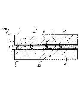
The exemplary embodiment represented in Figure 2
shows the design of the liquid-crystal multiple glazing
according to the invention in a first embodiment.
CA 02861730 2014-06-26
- 15 -
On two sheets of float glass 1 and 1',
electrically conductive layers 3, 4 with a thickness of
about 20 to 400 nm, having external surfaces 21, 31 and
made for example of indium tin oxide (ITO), are
arranged on the internal faces 11, 21. The ITO layers
have an electrical sheet resistance of between 5 SWE
and 300 WO. Instead of layers made of ITO, other
layers of electrically conductive oxide or layers of
silver whose sheet resistance is comparable may also be
used for the same purpose.
The layer 5 of liquid crystals, which may have a
thickness of about 5 to 15 pm (excluded), is placed
between the electrode layers 3 and 4. The thickness is
preferably at least 8 pm and even 10 pm
(approximately).
The layer 5 of liquid crystals contains spherical
spacers. The spacers 6 consist of a transparent
polymer.
In order to ensure uniformity of the thickness E
of the liquid-crystal layer 5 and thus ensure the
optical performance of the glazing with liquid
crystals, glass panes 1, l' with their electrodes 3, 4
are each selected with a dioptric defect score
according to the invention, which score is measured by
umbrascopy in reflection.
The basic principle is associated with the
geometrical optics. The diagram of the layout is
represented in Figure 3.
From a very thin source, such as a projector 100,
a light flux is projected onto the face of the glass
sheet 11 (coated or not with the electrode) intended to
be the internal face. A projected image is observed on
a screen 300 after reflection from the internal face 11
of the glass sheet. This image is acquired by a digital
camera 200 in order to be processed. The reflection
from the second face 12 is neutralized by using a
wetted black fabric which is placed behind the glass
cA028617302()14-06-26
- 16 -
pane 1 and on which the glass is bonded by capillary
effect.
Figure 4 indicates the principle of the formation
of an umbrascopic image on the screen 300 on the basis
of a planarity profile Y(x) of the glass. A concave
region on the glass pane (convergent defect) causes
concentration of the incident reflected light 110 and
therefore local over-illumination on the screen 300. A
complex region on the glass (divergent defect) causes
spreading of the incident reflected light 120 and
therefore local under-illumination on the screen 300.
Figure 5 shows an example of a local illumination
profile E(x) and an average illumination profile E0(x).
When the local illumination E(x) is equal to the
average illumination E0(x), the contrast is zero and
consequently Y" (x) = 0 and the optical power is zero.
When the local illumination E(x) is greater than
the average illumination E0(x), the contrast is
negative and Y'' (x) < 0. A convergent defect is
therefore involved, which corresponds to a concavity on
the glass pane.
When the local illumination E(x) is less than the
average illumination E0 (x), the contrast is positive
and Y'' (x) > 0. A divergent defect is therefore
involved, which corresponds to a convexity on the glass
pane.
Knowing that the planarity variations are more
significant in the direction of the overall width, in
order to explain the operating principle of the
apparatus we will consider a planarity profile in the
plane perpendicular to the casting direction and
perpendicular to the surface of the glass.
It can be shown on the basis of the laws of
geometrical optics and conservation of energy that
there is a relationship between the illumination E(x)
measured on the screen corresponding to an abscissa
CA 02861730 2014-06-26
- 17 -
point x on the glass pane and the profile Y(x) of the
surface of the glass pane.
Certain geometrical simplifications made on the
basis of the following aspects: the layout is in quasi-
normal reflection and the source is considered to be a
point source, give the following relationship:
d2Y(x) 1( E
= 0 1)
dx 2 D E(x)
with:
Y(x): profile of the glass pane
D: the glass pane - screen distance
Eo: average illumination at x (that which would be
obtained without a planarity defect)
Let the optical reflection power ORP (in
dioptres) be:
ORP = 2x d2Y(x) 2x C(x)
dx2
with the contrast C(x) such that
C(x)= Eo
E(x)
The contrast corresponds to the visual perception
of the "linearity" (here in dashes because a profile
rather than a surface is being considered) observed on
the umbrascopic image projected onto the screen.
Processing software calculates the contrast, and
therefore the optical reflection power ORP, for each
pixel of the image.
The dioptric defect score (in millidioptres)
reflects the homogeneity of the optical powers and is
in fact the standard deviation a of the distribution of
the optical reflection powers over the internal face,
defined by the relationship:
cs= (0 .P .r2 ) - (0.P .r),,j2
CA 02861730 2014-06-26
- 18 -
with
(O.P.r2)õ : mean square of the optical powers over the
entire internal face
(O.P.r),42 : square of the mean of the optical powers over
the entire internal face.
The score must be less than or equal to 2+2% in
order to ensure a sufficient optical quality in
transmission, that is to say a good homogeneity of the
light transmission in the "off" state.
for a thickness of liquid crystals of 12 pm, a
score of less than equal to 10 is needed.
For a thickness of liquid crystals of 10 pm, a
score of less than equal to 8.7 is needed.
For a thickness of liquid crystals of 8 pm, a
score of less than equal to 7.3 is needed.
By way of example, with a float line having a
capacity of 600 tonnes/day with a raw glass width of
3.5 m:
- the score of the 2.1 mm glass is less than 22
mdt,
- the score of the 3 mm glass is less than 11
mdt,
- the score of the 4 mm glass is less than
approximately 8 mdt,
- the score of the 6 mm glass is less than or
equal to approximately 5 mdt.
Furthermore, it is also possible to use known
compounds for the layer of liquid crystals, for example
the compounds described in Document US 5 691 795. The
liquid-crystal compound from Merck Co., Ltd, marketed
under the brand name "Cyanobiphenyl Nematic Liquid
Crystal E-31 LV" has also proven particularly suitable.
In the case of this embodiment, this product is mixed
in a ratio of 10:2 with a chiral substance, for example
4-cyano-4'-(2-methyl)butylbiphenyl, and this mixture is
mixed in a ratio of 10:0.3 with a monomer, for example
CA 02861730 2014-06-26
- 19 -
4,4'-bisacryloylbiphenyl, and with a UV initiator, for
example benzoin methyl ether. The mixture prepared in
this way is applied onto one of the coated glass
sheets. After curing of the layer of liquid crystals by
irradiation with a UV light, a polymer network is
formed in which the liquid crystals are incorporated.
For the layer of liquid crystals, it is possible
to use PDLCs such as the compounds 4-((4-ethy1-2,6-
difluoropheny1)-ethiny1)-4'-propylbiphenyl and 2-
fluoro-4,4'-bis(trans-4-propylcyclohexyl)-biphenyl, for
example marketed by the company Merck under the
reference MDA-00-3506.
On the edge, the layer of liquid crystals is
sealed by an adhesive joint 5 which simultaneously
serves to firmly and permanently bond the glass sheets
1, 1'.
The adhesive joint material contains an epoxy
resin.
As shown in Figure 6, the joint 7 has a given
width L and is interrupted in its width by a plurality
of openings 81 to 84, each defining lateral joint ends
71 to 74'.
More precisely, the joint 7 is interrupted in its
width by two openings 81 to 82 facing a first edge of
the glazing and by two other openings 83, 84 facing a
second edge opposite to the first edge, these edges
corresponding to the edges of the assembly direction of
the glass panes, preferably by calendering.
For each opening, an additional material 7 forms
a bridge between the adjacent lateral ends of the
joint, in particular consisting of the said joint
material, thus forming material continuity as shown in
Figure 6b1s.
In the initial state ("off" state), that is to
say before the application of an electrical voltage,
this liquid-crystal glazing 100 is translucent, that is
to say it optically transmits but is not transparent.
CA 02861730 2014-06-26
- 20 -
As soon as the current is connected up, the layer of
liquid crystals changes under the effect of the
alternating electric field into the transparent state,
that is to say the state in which viewing is no longer
prevented.
The electrically controllable glazing with liquid
crystals is produced by using a method described in
detail below.
In an industrial installation for continuous
coating, by using the method of magnetic field enhanced
reactive sputtering, with float glass sheets according
to the invention, are coated in successive sputtering
chambers with a layer of ITO having an approximate
thickness of 100 nm.
Two separate glass sheets of the same size and
having the desired dimensions are cut from a large
sheet of glass coated in this way and are prepared for
continuation of the processing.
The two separate glass sheets cut to the desired
dimensions then firstly undergo a washing operation.
The liquid-crystal layer mixed with the spacers
is then applied onto one of the two glass sheets
processed in this way.
Since the two separate glass sheets are
subsequently connected permanently and closely to one
another on their edges by a joint, the edge part of the
glass sheet 1 is not coated over a width of about 2 to
10 mm.
The coating with the liquid-crystal compound is
carried out with the aid of an operation referred to as
drop-by-drop filling. In order to carry out the
operation, a drop-by-drop pouring apparatus is used
which makes it possible to deposit drops of liquid
crystals onto a glass substrate, the quantity poured
being finely adjustable.
In another embodiment of the method, in order to
print the layer of liquid crystals, a screen printing
CA 02861730 2014-06-26
- 21 -
fabric is used with a mesh the width of which is about
20 to 50 pm and the thread diameter of which is about
30 to 50 pm.
The adhesive layer forming the joint 7 is
likewise applied directly along the edge of the glass
sheet 24 before or after deposition of the layer of
liquid crystals. It may have a width of, for example,
from 2 to 10 mm.
As shown by Figure 7, the formation the plurality
of a plurality of openings 81 to 84 in the joint is
provided, with a size and distribution adapted to
remove the excess liquid-crystal layer, the openings 81
to 84 each defining two adjacent lateral ends 71 to 74'
of the joint 7.
Furthermore, in order to do this, the application
of the joint material is either discontinuous or is
continuous then followed by creation of openings (by
removing material 7).
This is followed by application of the additional
material 7' forming a bridge between the lateral ends
of the joint 71 to 74', preferably consisting of the
said joint material, thus forming material continuity.
When the two separate glass sheets have thus been
pressed against one another, the adhesive layer 7 is
compressed to the thickness E of the layer of liquid
crystals.
The openings 81 to 84 therefore Serve:
- to remove the excess liquid-crystal layer, and
therefore to better control the layer thickness
and thus avoid a loss of optical quality,
- to degas the layer of liquid crystals in order
to avoid the subsequent formation of bubbles in
the layer and thus again to avoid a loss of
optical quality.
At least two openings are preferably positioned
on the front edge of the calendering and at least two
openings on the rear edge of the calendering.
CA 02861730 2014-06-26
- 22 -
The width of the lateral ends is, for example, 10
mm. The more viscous the layer of liquid crystals is,
the greater is the number of openings used.
The calendering operation is subsequently carried
out, or as a variant the pressing.
If the layer of liquid crystals consists of a
mixture of liquid crystals and a monomer, the
polymerization operation is then carried out by
irradiation with UV light.