Language selection

Search

Patent 2861814 Summary

Third-party information liability

Some of the information on this Web page has been provided by external sources. The Government of Canada is not responsible for the accuracy, reliability or currency of the information supplied by external sources. Users wishing to rely upon this information should consult directly with the source of the information. Content provided by external sources is not subject to official languages, privacy and accessibility requirements.

Claims and Abstract availability

Any discrepancies in the text and image of the Claims and Abstract are due to differing posting times. Text of the Claims and Abstract are posted:

  • At the time the application is open to public inspection;
  • At the time of issue of the patent (grant).
(12) Patent Application: (11) CA 2861814
(54) English Title: MICROWAVE PLASMA BIOMASS GASIFYING FIXED BED GASIFIER AND PROCESS
(54) French Title: REACTEUR DE GAZEIFICATION DE BIOMASSE A LIT FIXE A PLASMA MICRO-ONDE ET PROCEDE CORRESPONDANT
Status: Deemed Abandoned and Beyond the Period of Reinstatement - Pending Response to Notice of Disregarded Communication
Bibliographic Data
(51) International Patent Classification (IPC):
  • C10J 3/02 (2006.01)
  • C10J 3/18 (2006.01)
  • C10J 3/20 (2006.01)
(72) Inventors :
  • CHEN, YILONG (China)
  • ZHANG, YANFENG (China)
  • XIA, MINGGUI (China)
  • ZHANG, LIANG (China)
(73) Owners :
  • WUHAN KAIDI GENERAL RESEARCH INSTITUTE OF ENGINEERING & TECHNOLOGY CO., LTD.
(71) Applicants :
  • WUHAN KAIDI GENERAL RESEARCH INSTITUTE OF ENGINEERING & TECHNOLOGY CO., LTD. (China)
(74) Agent: HERMAN IP
(74) Associate agent:
(45) Issued:
(86) PCT Filing Date: 2012-10-26
(87) Open to Public Inspection: 2013-07-04
Examination requested: 2017-10-26
Availability of licence: N/A
Dedicated to the Public: N/A
(25) Language of filing: English

Patent Cooperation Treaty (PCT): Yes
(86) PCT Filing Number: PCT/CN2012/083569
(87) International Publication Number: WO 2013097534
(85) National Entry: 2014-06-26

(30) Application Priority Data:
Application No. Country/Territory Date
201110449459.6 (China) 2011-12-29

Abstracts

English Abstract

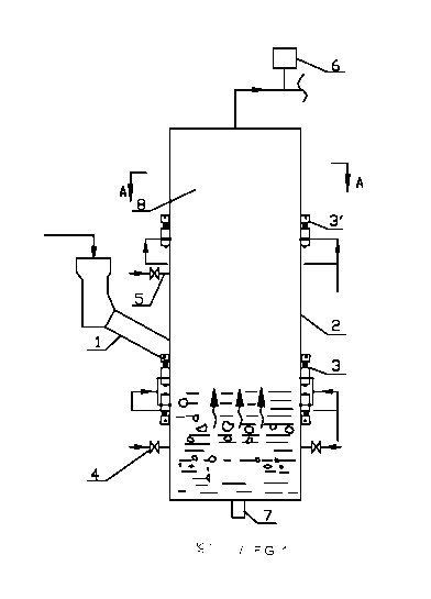
A microwave plasma biomass gasifying fixed bed gasifier comprising a vertically arranged gasifier body (2). The upper part of the gasifier body (2) is a gasifier clearance area (8). The lowest part of the gasifier body (2) is a fixed bed layer. Provided on the gasifier body are a raw material and fuel inlet, a product gas outlet, an oxygen/steam inlet (4 and 5). Provided at the bottom part of the gasifier body is a slug discharging outlet (7). Arranged at the product gas outlet is a synthesis gas monitoring unit (6). Arranged on the gasifier body is at least one section of microwave plasma generator (3). Also provided is a biomass gasification process utilizing the gasifier. The process comprises: 1) a biomass is fed into the gasifier via a feeder apparatus, and gasified on the microwave plasma fixed bed layer; a biomass fixed carbon content is subjected to a combustion reaction in an oxidation area on the bed layer, a high temperature flue gas is generated, the flue gas is transmitted upwards to a feeder area to heat a fuel fed into the gasifier, while at the same time, is subjected to a chemical reaction with high temperature steam injected from the lower layer oxygen/steam nozzle and an activity-rich microwave plasma-activated oxidizer of a first-section microwave plasma generator, where the temperature of a reaction area is controlled between 700°C and 1600°C; 2) a synthesis gas generated from the reaction is transmitted upwards to the clearance area, and is further cracked via a second-section microwave plasma generator; 3) a residual coke substance is transmitted downwards to the fixed bed layer to gradually release heat to maintain bed temperature, a burned biomass slag is discharged outside the gasifier via the slag discharging outlet; and 4) online monitoring is implemented via the synthesis gas monitoring unit arranged at the product gas outlet at the top part of the gasifier.


French Abstract

L'invention porte sur un réacteur de gazéification de biomasse à lit fixe à plasma micro-onde comprenant un corps (2) de réacteur de gazéification disposé verticalement. La partie supérieure du corps (2) de réacteur de gazéification est une zone espace libre (8) du réacteur de gazéification. La partie la plus basse du corps (2) de réacteur de gazéification est une couche de lit fixe. Sur le corps de réacteur de gazéification se trouvent une entrée de matière première et de combustible, une sortie de produit gazeux et une entrée d'oxygène/vapeur d'eau (4 et 5). Au niveau de la partie de fond du corps de réacteur de gazéification se trouve une sortie (7) d'évacuation de crasses. A la sortie de produit gazeux se trouve une unité (6) de suivi de gaz de synthèse. Sur le corps de réacteur de gazéification se trouve au moins une section de générateur (3) de plasma micro-onde. L'invention porte également sur un procédé de gazéification de biomasse utilisant le réacteur de gazéification. Le procédé comprend les étapes suivantes : 1) une biomasse est introduite dans le réacteur de gazéification par l'intermédiaire d'un appareil alimentateur doseur et elle est gazéifiée sur la couche de lit fixe par plasma micro-onde ; une teneur en carbone fixe de la biomasse est soumise à une réaction de combustion dans une zone d'oxydation sur la couche de lit, un gaz de combustion à haute température est produit, le gaz de combustion est transféré vers le haut vers une zone de l'alimentateur doseur pour chauffer un combustible introduit dans le réacteur de gazéification, alors qu'en même temps il est soumis à une réaction chimique avec de la vapeur d'eau à haute température injectée à partir de la buse d'oxygène/vapeur d'eau de couche inférieure et un oxydant activé par plasma micro-onde de forte activité d'un générateur de plasma micro-onde de première section, la température d'une zone de réaction étant régulée entre 700°C et 1600°C ; 2) un gaz de synthèse produit à partir de la réaction est transféré vers le haut vers la zone espace libre et il est encore craqué par l'intermédiaire d'un générateur de plasma micro-onde de seconde section ; 3) une substance constituée de coke résiduel est transférée vers le bas vers la couche de lit fixe pour libérer progressivement de la chaleur et maintenir la température du lit, des crasses de biomasse brûlée sont évacuées à l'extérieur du réacteur de gazéification par l'intermédiaire de la sortie d'évacuation de crasses ; et 4) un suivi en ligne est mis en uvre par l'intermédiaire de l'unité de suivi de gaz de synthèse disposée à la sortie de produit gazeux au niveau de la partie supérieure du réacteur de gazéification.

Claims

Note: Claims are shown in the official language in which they were submitted.


CLAIMS
1. A microwave plasma based fixed bed gasifier of biomass, comprising a
vertically
disposed furnace body, a monitoring unit, and a microwave plasma generating
device,
the furnace body comprising a material and fuel inlet, a syngas outlet, an
oxygen/vapor inlet, and a slag outlet, wherein the furnace body comprises a
clearance
zone in an upper part thereof and a fixed bed zone in a lower part thereof;
the slag
outlet is disposed at a bottom of the furnace body; the monitoring unit is
disposed
close to the syngas outlet; and at least one microwave plasma generating
device is
disposed on the furnace body.
2. The gasifier of claim 1, characterized in that a first microwave plasma
generating
device is disposed between the fixed bed zone in the lower part of the furnace
body
and the material and fuel inlet, and a second microwave plasma generating
device is
disposed in the clearance zone in the upper part of the furnace body; the
first
microwave plasm.a generating device comprises two or three layers of microwave
plasma generators, the second microwave plasma generating device comprises one
or
two layers of microwave plasma generators, and each layer of the microwave
plasma
generators comprises three or four evenly distributed working gas inlets.
3. The gasifier of claim 2, characterized in that the first microwave plasma
generator
has large power and small electrode gap, and produces high temperature of
plasma;
the second microwave plasma generator has large electrode gap, strong plasma
activity, and wide volume range.
9

4. The gasifier of claim 3, characterized in that a microwave power source
of the
microwave plasma generators has a basic frequency of 2.45 GHz, and a power of
a
single microwave plasma generator is within 200 kW.
5. The gasifier of any one of claims 1-4, characterized in that an upper
oxygen/vapor
nozzle is disposed in the clearance zone of the furnace body, and a lower
oxygen/vapor nozzle is disposed in the fixed bed zone of the furnace body.
6. A method of gasification using the gasifier of any one of preceding
claims, the
method comprising:
1) feeding biomass fuel and waste into the furnace body via a feeder, allowing
the
biomass fuel and waste to be combusted and gasified in the fixed bed zone to
yield high temperature flue gas, allowing the flue gas to flow upward to
exchange
heat with newly-fed biomass fuel and waste in A feeding zone of the gasifier,
and
meanwhile allowing the flue gas to react with vapor sprayed from the lower
oxygen/vapor nozzle and with a plasma oxidizer generated by the first
microwave plasma generator to yield syngas, of which a chemical equation
being:
2C + O2 = 2CO, C + H2O = CO + H2, a gasification temperature being between
700 and 1600°C;
2) allowing the syngas to flow upward to the clearance zone, where tars in the
syngas are cracked and hydrocarbons in the syngas are converted in the
presence
of plasma generated by the second microwave plasma generator;
3) allowing coke residues to fall downward to the fixed bed zone and release
thermal energy to maintain the temperature of the fixed bed zone, and
discharging slags from the slag outlet; and

4) monitoring in real time a temperature and components of the syngas by the
monitoring unit disposed close to the syngas outlet to maintain process
parameters within a preset range.
7. The method of claim 6, characterized in that in step 1), the
gasification temperature
is between 700 and 1600°C; and in step 4), the temperature of the
syngas is within
1200°C.
8. The method of claim 7, characterized in that in step 1), the gasification
temperature
is between 750 and 950°C.
9. The method of claim 7 or 8, characterized in that in step 1), the vapor
sprayed from
the lower oxygen/vapor nozzle operates to increase the vapor concentration
thereby
prompting the reaction between the carbon residues and the vapor; in step 2),
a total
power of the second microwave plasma generator meets the requirement for
supplying thermal energy for the reaction equilibrium; the appropriate high
temperature vapor is sprayed from the upper oxygen/vapor nozzle to prompt the
cracking reaction of the tars.
11

Description

Note: Descriptions are shown in the official language in which they were submitted.


CA 02861814 2014-06-26
MICROWAVE PLASMA BIOMASS GASIFYING FIXED BED GASIFIER AND
PROCESS
FIELD OF THE INVENTION
[0001] The invention relates to the gasification of biomass and solid wastes,
and more
particularly to a gasifier and a method for gasifying biomass and solid wastes
to
synthesize high quality syngas in the presence of microwave plasma.
BACKGROUND OF THE INVENTION
[0002] China is rich in biomass resources including cotton stalks, straw,
twigs, and rice
husk. As conventional primary energy sources such as fossil fuel are daily
decreasing,
people pay more and more attention to low calorific fuels.
[0003] Meanwhile, with the growing of environmental awareness, higher
efficiency and
lower contamination of high technology has gradually been adopted by
industrial
production.
[0004] Currently, the fixed bed gasification has defects such as low
gasification
temperature, high tar content, and low-quality syngas. Low gasification
temperature
results in high content of tar in the syngas. The tar is difficult to remove
and easily blocks
and corrodes the valves, pipes, and auxiliary equipment. The removal of the
tar costs
much. With the development of microwave technology, microwave plasma, with its
own
excellent characteristics, has widely applied to low temperature chemical
vapor
deposition gradually (CVD), rapid preparation of optical fibers, submicron
etching of
chips, surface modification of polymer materials, microelectronic materials
processing,
and so on.
[0005] The invention adopts microwave and plasma to gasify biomass fuel with
high
1

CA 02861814 2014-06-26
efficiency, which provides a new way for the synthesis of syngas using biomass
fuel and
wastes.
SUMMARY OF THE INVENTION
[0006] In view of the above-described problems, it is one objective of the
invention to
provide a fixed bed gasifier and a method using the same for the gasification
of biomass
to synthesize high quality syngas, particularly to synthesize the syngas
comprising CO
and H2 with characteristics of economy and high efficiency.
[0007] To achieve the above objective, the following technical schemes are
adopted.
[0008] A microwave plasma based fixed bed gasifier of biomass, comprising a
vertically
disposed furnace body, a monitoring unit, and a microwave plasma generating
device, the
furnace body comprising a material and fuel inlet, a syngas outlet, an
oxygen/vapor inlet,
and a slag outlet, wherein the furnace body comprises a clearance zone in an
upper part
thereof and a fixed bed zone in a lower part thereof; the slag outlet is
disposed at a
bottom of the furnace body; the monitoring unit is disposed close to the
syngas outlet;
and at least one microwave plasma generating device is disposed on the furnace
body.
[0009] Preferably, a first microwave plasma generating device is disposed
between the
fixed bed zone in the lower part of the furnace body and the material and fuel
inlet, and a
second microwave plasma generating device is disposed in the clearance zone in
the
upper part of the furnace body; the first microwave plasma generating device
comprises
two or three layers of microwave plasma generators, the second microwave
plasma
generating device comprises one or two layers of microwave plasma generators,
and each
layer of the microwave plasma generators comprises three or four evenly
distributed
working gas inlets.
[0010] Preferably, the first microwave plasma generator has large power and
small
2

CA 02861814 2014-06-26
electrode gap, and produces high temperature of plasma; the second microwave
plasma
generator has large electrode gap, strong plasma activity, and wide volume
range.
[0011] Preferably, a microwave power source of the microwave plasma generators
has a
basic frequency of 2.45 0I-1z, and a power of a single microwave plasma
generator is
within 200 kW
[0012] Preferably, an upper oxygen/vapor nozzle is disposed in the clearance
zone of the
furnace body, and a lower oxygen/vapor nozzle is disposed in the fixed bed
zone of the
furnace body.
[0013] A method of gasification using the gasifier comprises:
[0014] 1) feeding biomass fuel and waste into the furnace body via a feeder,
allowing the
biomass fuel and waste to be combusted and gasified in the fixed bed zone to
yield high
temperature flue gas, allowing the flue gas to flow upward to exchange heat
with
newly-fed biomass fuel and waste in a feeding zone of the gasifier, and
meanwhile
allowing the flue gas to react with vapor sprayed from the lower oxygen/vapor
nozzle and
with a plasma oxidizer generated by the first microwave plasma generator to
yield syngas,
of which a chemical equation being: 2C + 02= 2CO3 C + 1120 = CO + H2, a
gasification
temperature being between 700 and 1600 C;
[0015] Within the temperature range, the microwave-excited plasma oxidizer has
high
degree of ionization, high degree of dispersion, and strong oxidation activity
and
chemical reactivity. Thus, even in a relatively low ambient temperature, the
chemical
reaction can proceed. The conversion efficiency of the biomass fuel is high,
and the
syngas comprising CO and H2 has high quality and little tars;
[0016] 2) allowing the syngas to flow upward to the clearance zone, where tars
in the
syngas are cracked and hydrocarbons in the syngas are converted in the
presence of
plasma generated by the second microwave plasma generator;
3

CA 02861814 2014-06-26
[0017] 3) allowing coke residues to fall downward to the fixed bed zone and
release
thermal energy to maintain the temperature of the fixed bed zone, and
discharging slags
from the slag outlet; and
[0018] 4) monitoring in real time a temperature and components of the syngas
by the
monitoring unit disposed close to the syngas outlet to maintain process
parameters within
a preset range.
[0019] In step 1), the gasification temperature is between 700 and 1600 C; and
in step 4),
the temperature of the syngas is within 1200 C.
[0020] In step 1), the gasification temperature is between 750 and 950 C.
[0021] In step 1), the vapor sprayed from the lower oxygen/vapor nozzle
operates to
increase the vapor concentration thereby prompting the reaction between the
carbon
residues and the vapor; in step 2), a total power of the second microwave
plasma
generator meets the requirement for supplying thermal energy for the reaction
equilibrium; in step 2), the appropriate high temperature vapor is sprayed
from the upper
oxygen/vapor nozzle to prompt the cracking reaction of the tars.
[0022] Advantages according to embodiments of the invention are summarized as
follows.
[0023] 1. In the presence of high degree of ionization and high degree of
dispersion of
microwave plasma, the biomass fuel in the gasifier is converted with high
efficiency, and
the cold gas efficiency is significantly improved compared to that in
conventional
gasification processes, exceeding 85%.
[0024] 2. The microwave plasma generator disposed in the clearance zone of the
gasifier
facilitates the unbalance cracking of tars in the syngas, and thus the syngas
contains little
or no tars, which can be directly used in industry, with simple process and
good economic
efficiency.
4

CA 02861814 2014-06-26
[0025] 3. The gasifier has no specific requirement on the particle size of
biomass fuel,
primary crushing can meet the requirement of particle size, and thus the
production costs
are low, with good economic efficiency.
BRIEF DESCRIPTION OF THE DRAWINGS
[0026] FIG. 1 shows a schematic diagram of a fixed bed gasifier of biomass and
a flow
chart of a gasification method using the same according to one embodiment of
the
invention.
[0027] FIG. 2 is a sectional view taken from Line A-A of FIG. 1.
[0028] In the drawings, the following reference numbers are used: 1. Feeder;
2. Furnace
body; 3. Microwave plasma generator; 4. Lower oxygen/vapor nozzle; 5. Upper
oxygen/vapor nozzle; 6. Monitoring unit; 7. Slag outlet; 8. Clearance zone of
gasifier.
DETAILED DESCRIPTION OF THE EMBODIMENTS
[0029] For further illustrating the invention, experiments detailing a
gasifier and a
method for gasifying biomass and solid wastes to synthesize high quality
syngas are
described below. It should be noted that the following examples are intended
to describe
and not to limit the invention.
[0030] A furnace body 2 is a vertically disposed cylinder, a clearance zone 8
is disposed
at the uppermost of the furnace body, and a fixed bed zone receiving microwave
plasma
is disposed at the lowermost of the furnace body. A vertical downward slag
outlet 7 is
disposed at a bottom of the furnace body. An upper oxygen/vapor nozzle 5 is
disposed in
the clearance zone 8 of the furnace body, and a lower oxygen/vapor nozzle 4 is
disposed
in the fixed bed zone of the furnace body. Both the nozzles can be controlled
by switches

CA 02861814 2014-06-26
to regulate the flow rate. The furnace body 2 is cylindrical, or a combination
of a cone
and a cylinder.
100311 A feeder 1 is disposed in the middle of the furnace body 2 and
communicates with
the furnace body 2 via an inclined feeding chute. The feeding mode can
optionally be
screw feeding, without the need of the inclined feeding chute.
[0032] The number of the microwave plasma generator is determined by the
content of
moisture and volatile components in the biomass fuel. As the biomass fuel
contains high
content of moisture (about 20%) and low caloric value, in this example, the
first
microwave plasma generating device comprises two or three layers of microwave
plasma
generators 3 (in FIG. 1, there are two layers of microwave plasma generators),
which are
centrally disposed below the feeder 1 and slightly higher than the bed
material position in
the fixed bed, and each layer of the microwave plasma generators comprises
three or four
evenly distributed working gas inlets. The similar arrangement of the
microwave plasma
generators such as being disposed above the feeder is also acceptable. The
second
microwave plasma generating device is disposed in the clearance zone which is
above the
feeder 1, and comprises one or two layers of microwave plasma generators, each
layer of
the microwave plasma generators comprises three or four evenly distributed
working gas
inlets (in FIG. 2, there are three working gas inlets).
[0033] The first microwave plasma generator 3 has large power and small
electrode gap,
and produces high temperature of plasma; the second microwave plasma generator
3' has
large electrode gap, strong plasma activity, and wide volume range, which is
configured
to crack the tars in the syngas, and to convert hydrocarbons such as methane
in the syngas.
Finally, the tar content in the syngas is reduced to meet the direct usage
level in industry,
and the hydrocarbon content is also reduced, which is conducive to the
subsequent carbon
removal.
[0034] The microwave power source of the microwave plasma generators has a
basic
6

CA 02861814 2014-06-26
frequency of 2.45 GHz, and a power of a single microwave plasma generator is
within
200 kW.
[0035] The total power of the second microwave plasma generator meets the
requirement
for supplying thermal energy for the reaction equilibrium.
[0036] A monitoring unit 6 is disposed close to the syngas outlet at the top
of the furnace
body 2 to monitor in real time the temperature and components of the syngas to
maintain
process parameters within a preset range.
[0037] The biomass fuel and waste are fed into the furnace body 2 via the
feeder 1 and
gasified quickly in the fixed bed zone of the gasifier. Firstly, the fuel
particles are
pyrolyzed under high temperature to yield a large amount of volatile
components and
semi-coke residues. The volatile components react with oxygen and vapor in the
presence
of high activity of plasma generated by the microwave plasma generator. To
regulate the
temperature of the fixed bed zone can ensure the smooth operation of the
gasification
process. If the furnace temperature is too low, the working gas such as oxygen
should be
complemented in large, and meanwhile the microwave power of the microwave
plasma
generator 3 and the flow rate of the working gas are adjusted accordingly,
vice versa. The
vapor sprayed from the lower oxygen/vapor nozzle 4 operates to increase the
vapor
concentration, thereby prompting the reaction between the carbon residues and
the vapor,
improving the yield of 112, inhibiting the formation of the tars in the
reaction zone, and
enhancing the quality of the syngas.
[0038] With the feeding and gasification of the biomass fuel, the syngas flows
upwards to
the clearance zone and is cracked. The coke residues fall downwards to the
fixed bed
zone and release heat energy to maintain the temperature therein. The
resulting slag is
discharged from the slag outlet 7. In the clearance zone 8, the syngas is
further cracked in
the presence of high degree of ionization and high activity of plasma
generated by the
second microwave plasma generator. Appropriate high temperature vapour is
sprayed
7

CA 02861814 2014-06-26
from the upper oxygen/vapor nozzle 5 for further cracking the tars in the
syngas. Thus,
the tar content is greatly reduced, which is conducive to the subsequent
application.
[0039] The gasification temperature is between 700 and 1600 C; and the
temperature of
the syngas is within 1200 C. The gasification temperature is between 750 and
950 C.
[0040] To achieve the optimal working conditions and satisfy the overall
performance
requirement of the gasification, the key is to control the temperature of the
entrained flow
bed, and to regulate the oxygen flow rate, vapor flow rate, and microwave
power. The
monitoring unit disposed close to the syngas outlet can monitor the above
parameters in
real time, thereby controlling the gasification process by clia-in and by full
automation and
maintaining the operation stability of the gasifier.
[0041] While particular embodiments of the invention have been shown and
described, it
will be obvious to those skilled in the art that changes and modifications may
be made
without departing from the invention in its broader aspects, and therefore,
the aim in the
appended claims is to cover all such changes and modifications as fall within
the true
spirit and scope of the invention.
8

Representative Drawing
A single figure which represents the drawing illustrating the invention.
Administrative Status

2024-08-01:As part of the Next Generation Patents (NGP) transition, the Canadian Patents Database (CPD) now contains a more detailed Event History, which replicates the Event Log of our new back-office solution.

Please note that "Inactive:" events refers to events no longer in use in our new back-office solution.

For a clearer understanding of the status of the application/patent presented on this page, the site Disclaimer , as well as the definitions for Patent , Event History , Maintenance Fee  and Payment History  should be consulted.

Event History

Description Date
Inactive: Dead - No reply to s.30(2) Rules requisition 2020-08-31
Application Not Reinstated by Deadline 2020-08-31
Inactive: COVID 19 - Deadline extended 2020-08-19
Inactive: COVID 19 - Deadline extended 2020-08-06
Inactive: COVID 19 - Deadline extended 2020-07-16
Inactive: COVID 19 - Deadline extended 2020-07-02
Inactive: COVID 19 - Deadline extended 2020-06-10
Inactive: COVID 19 - Deadline extended 2020-05-28
Inactive: COVID 19 - Deadline extended 2020-05-14
Common Representative Appointed 2019-10-30
Deemed Abandoned - Failure to Respond to Maintenance Fee Notice 2019-10-28
Inactive: Abandoned - No reply to s.30(2) Rules requisition 2019-05-27
Inactive: S.30(2) Rules - Examiner requisition 2018-11-27
Inactive: Report - No QC 2018-11-22
Maintenance Request Received 2018-10-25
Letter Sent 2017-11-01
Request for Examination Requirements Determined Compliant 2017-10-26
All Requirements for Examination Determined Compliant 2017-10-26
Request for Examination Received 2017-10-26
Maintenance Request Received 2017-10-26
Maintenance Request Received 2016-10-26
Maintenance Request Received 2015-10-26
Maintenance Request Received 2014-10-24
Inactive: Cover page published 2014-09-30
Inactive: First IPC assigned 2014-09-09
Inactive: Notice - National entry - No RFE 2014-09-09
Inactive: IPC assigned 2014-09-09
Application Received - PCT 2014-09-09
National Entry Requirements Determined Compliant 2014-06-26
Application Published (Open to Public Inspection) 2013-07-04

Abandonment History

Abandonment Date Reason Reinstatement Date
2019-10-28

Maintenance Fee

The last payment was received on 2018-10-25

Note : If the full payment has not been received on or before the date indicated, a further fee may be required which may be one of the following

  • the reinstatement fee;
  • the late payment fee; or
  • additional fee to reverse deemed expiry.

Patent fees are adjusted on the 1st of January every year. The amounts above are the current amounts if received by December 31 of the current year.
Please refer to the CIPO Patent Fees web page to see all current fee amounts.

Fee History

Fee Type Anniversary Year Due Date Paid Date
Basic national fee - standard 2014-06-26
MF (application, 2nd anniv.) - standard 02 2014-10-27 2014-10-24
MF (application, 3rd anniv.) - standard 03 2015-10-26 2015-10-26
MF (application, 4th anniv.) - standard 04 2016-10-26 2016-10-26
Request for examination - standard 2017-10-26
MF (application, 5th anniv.) - standard 05 2017-10-26 2017-10-26
MF (application, 6th anniv.) - standard 06 2018-10-26 2018-10-25
Owners on Record

Note: Records showing the ownership history in alphabetical order.

Current Owners on Record
WUHAN KAIDI GENERAL RESEARCH INSTITUTE OF ENGINEERING & TECHNOLOGY CO., LTD.
Past Owners on Record
LIANG ZHANG
MINGGUI XIA
YANFENG ZHANG
YILONG CHEN
Past Owners that do not appear in the "Owners on Record" listing will appear in other documentation within the application.
Documents

To view selected files, please enter reCAPTCHA code :


To view images, click a link in the Document Description column. To download the documents, select one or more checkboxes in the first column and then click the "Download Selected in PDF format (Zip Archive)" or the "Download Selected as Single PDF" button.

List of published and non-published patent-specific documents on the CPD .

If you have any difficulty accessing content, you can call the Client Service Centre at 1-866-997-1936 or send them an e-mail at CIPO Client Service Centre.


Document
Description 
Date
(yyyy-mm-dd) 
Number of pages   Size of Image (KB) 
Description 2014-06-25 8 311
Drawings 2014-06-25 2 14
Claims 2014-06-25 3 90
Abstract 2014-06-25 1 41
Representative drawing 2014-06-25 1 5
Reminder of maintenance fee due 2014-09-08 1 113
Notice of National Entry 2014-09-08 1 206
Reminder - Request for Examination 2017-06-27 1 119
Acknowledgement of Request for Examination 2017-10-31 1 176
Courtesy - Abandonment Letter (R30(2)) 2019-07-07 1 167
Courtesy - Abandonment Letter (Maintenance Fee) 2019-12-08 1 171
Maintenance fee payment 2018-10-24 2 55
Examiner Requisition 2018-11-26 5 259
PCT 2014-06-25 5 197
Fees 2014-10-23 2 66
Maintenance fee payment 2015-10-25 2 63
Maintenance fee payment 2016-10-25 2 57
Maintenance fee payment 2017-10-25 2 67
Request for examination 2017-10-25 2 67