Note: Descriptions are shown in the official language in which they were submitted.
CA 02862099 2014-07-21
- 1 -
102-090-P1
DESCRIPTION
PLUG FOR USE IN PIERCING MACHINE AND REGENERATING METHOD
OF PLUG
Technical Field
The present invention relates to a plug for use in a
piercing machine and a regenerating method of a plug and,
more particularly, to a plug for use in a piercing
machine and a regenerating method of producing a plug by
using a used plug.
Background Art
Piercing machines are used in manufacturing seamless
steel pipes in the Mannesmann process. A piecing machine
includes a pair of skew rolls and a plug. The plug is
disposed between the pair of the skew rolls, and is
located on a pass line. The piercing machine pushes and
squeezes a billet over the plug while rotating the billet
in the circumferential direction with the skew rolls, so
as to piercing-roll the billet into a hollow shell.
The piercing machine piercing-rolls a billet heated
at a high temperature. Hence, the plug over which the
billet is pushed and squeezed is subjected to a high
temperature and a high pressure. Consequently, melting
loss and scoring are likely to be caused to the plug.
In general, oxide scale is formed on the surface of
a plug base metal. Such an oxide scale blocks heat from
CA 02862099 2014-07-21
- 2 -
102-090-P1
the billet so as to reduce generation of the melting loss.
The oxide scale also reduces generation of the scoring.
Unfortunately, the oxide scale is gradually reduced
every time the billet is piercing-rolled. If the oxide
scale is exhausted, the temperature of the plug base
metal begins to increase, which causes the melting loss
to the plug.
In order to enhance the usage count of the plug, it
has been proposed not only to form a scale on the surface
of the plug base metal, but also to adjust a chemical
composition of the base metal (see JP4-8498B, JP4-74848A,
JP4-270003A, and JP64-7147B, for example).
In order to enhance the usage count of the plug, it
has been proposed to form a coating other than the scale
on the surface of the plug base metal (see JP10-180315A,
and JP4279350B, for example).
Disclosure of the Invention
Recently, further enhancement of the usage count of
a plug has been desired.
A method of regenerating a plug on which melting
loss occurs is disclosed in JP2976858B. In JP2976858B,
the plug has a parallel portion. The parallel portion
has the same diameter as the maximum diameter of the plug,
and extends rearward from the portion at the maximum
diameter. In such a plug, the portion at the maximum
diameter is shifted rearward when cutting a front end
portion of the plug on which melting loss occurs.
CA 02862099 2014-07-21
- 3 -
102-090-P1
Unfortunately, the oxide scale is formed on the
surface of the plug base metal in JP2976858B. The oxide
scale is formed by eroding the base metal. Accordingly,
as the oxide scale becomes worn away, the maximum
diameter of the plug gradually becomes reduced. For this
reason, the usage count of the plug should be limited.
The objective of the present invention is to provide
a plug and a regenerating method of a plug capable of
enhancing the usage count of the plug, which is for use
in a piercing machine of piercing-rolling-a billet.
A plug according to an aspect of the present
invention is for use in a piercing machine for piercing-
rolling a billet. The plug includes a body, a columnar
portion, and a sprayed film. The body has a maximum
diameter at its rear end. The columnar portion has the
same diameter as the diameter of the rear end of the body,
and extends from the rear end of the body. The sprayed
film is formed on the surface of the body, and on the
surface of the columnar portion.
A regenerating method of the plug according to
another aspect of the present invention includes a
preparing step, a cutting step, and a forming step. In
the preparing step, a plug used in the piercing-rolling
is prepared. In the cutting step, the plug is cut, so as
to remove the sprayed film, and the body is shifted more
rearward compared to the plug before the cutting. In the
forming step, the sprayed film is newly formed on the
CA 02862099 2014-07-21
- 4 -
102-090-P1
surface of the body, and on the surface of the columnar
portion after the cutting.
According to the plug and the regenerating method of
the plug of the embodiments of the present invention, the
usage count of the plug is enhanced.
Brief Description of the Drawings
Figure 1 is a longitudinal section view of a plug
according to a first embodiment of the present invention;
Figure 2 is a schematic diagram showing a
configuration of a piercing machine in which the plug of
Figure 1 is used;
Figure 3A is a longitudinal section view showing the
plug after the cutting;
Figure 3B is a longitudinal section view showing a
regenerated plug;
Figure 4 is a longitudinal section view of a plug
according to a second embodiment of the present
invention;
Figure 5 is a schematic diagram showing a relation
between a build-up layer on the plug of Figure 4 and
gorging portions of skew rolls;
Figure 6A is a longitudinal section view showing the
plug body and the build-up layer after the sprayed film
is removed;
Figure 6B is a longitudinal section view showing the
plug body and the build-up layer after the cutting;
CA 02862099 2014-07-21
- 5 -
102-090-P1
Figure 6C is a longitudinal section view showing a
regenerated plug;
Figure 7 is a longitudinal section view of a plug
according to a third embodiment of the present invention;
Figure 8 is a longitudinal section view showing a
plug of a comparative example;
Figure 9 is a graph showing a relation between the
variation at a front end and the count of a piercing
pass;
Figure 10 is a graph showing a relation between the
reduction of the maximum diameter and the count of the
piercing pass;
Figure 11 is a graph showing a relation between the
variation at the front end and the count of the piercing
pass; and
Figure 12 is a graph showing a relation between the
reduction of the maximum diameter and the count of the
piercing pass.
Mode for Carrying Out the Invention
A plug according to an embodiment of the present
invention is for use in a piercing machine to piercing-
roll a billet. The plug includes a body, a columnar
portion, and a sprayed film. The body has the maximum
diameter at the rear end thereof. The columnar portion
has the same diameter as that of the rear end of the body,
and extends from the rear end of the body. The sprayed
CA 02862099 2014-07-21
- 6 -
102-090-P1
film is formed on the surface of the body, and also on
the surface of the columnar portion.
The sprayed film has a greater hot strength than
that of an oxide scale. Accordingly, the plug according
to an embodiment of the present invention becomes harder
to be worn away compared to a plug having the oxide scale
formed on its surface. As a result, the usage count of
the plug becomes enhanced.
The columnar portion has the same diameter as that
of the rear end of the body, and extends from the rear
end of the body. If the body is melted, the melted
portion is removed, and the columnar portion is cut so as
to restore the shape and size of the body to its shape
and size before the melting loss (to the original shape
and size). Specifically, the axial direction length of
the columnar portion is reduced, and the rear end of the
body is shifted rearward, thereby restoring the body to
have its original shape and size. This enhances the
usage count of the plug.
It is preferable to further provide a build-up layer
formed on the surface of the body. The sprayed film is
formed on the surface of the body in a region more
rearward than the build-up layer, and also formed on the
surface of the columnar portion.
At the time of piercing-rolling the billet, the body
of the plug comes in contact with the billet; thus the
body is likely to be melted. For this reason, the build-
up layer having a greater hot strength is formed on this
CA 02862099 2014-07-21
- 7 -
102-090-P1
portion likely to be melted. Accordingly, the hot
strength of the body is enhanced; thus the body becomes
unlikely to be melted.
To the contrary, scoring is more easily caused if
the build-up layer is formed on the entire surface of the
plug. To counter this, in the plug according to the
embodiment, the sprayed film is formed on the side
surface of the plug. The sprayed film is more excellent
in scoring resistance than the build-up layer is. Hence,
in the plug according to the embodiment, the build-up
layer reduces the melting loss, and the sprayed film
reduces the scoring. Accordingly, the usage count of the
plug is enhanced.
If the build-up layer is melted, the axial direction
length of the columnar portion is reduced, so as to
remove the melted portion, and to restore the shape and
size from the front end to the portion at the maximum
diameter of the plug to its shape and size before the
melting loss (to its original shape and size).
Specifically, the shape and size from the front end to
the portion at the maximum diameter can be restored to
its original shape and size by shifting the rear end of
the body rearward. Accordingly, it is possible to
enhance the usage count of the plug that is usable as a
plug having the identical size.
The front end portion of the body is preferably
covered with the build-up layer. In this configuration,
CA 02862099 2014-07-21
- 8 -
102-090-P1
the front end portion of the body becomes unlikely to be
melted.
In the case of covering the front end portion of the
body with the build-up layer, it is preferable that the
thickness of the front end portion of the build-up layer
is equal to or smaller than the axial direction length of
the columnar portion. In this configuration, the plug
may be cut immediately before the front end portion of
the build-up layer becomes lost.
The body preferably includes a first body portion
and a second body portion. The second body portion has a
greater diameter than that of the rear end of the first
body portion, and extends from the rear end of the first
body portion. The build-up layer is formed on the
surface of the first body portion. The sprayed film is
formed on the surface of the second body portion.
In this case, even if the build-up layer is
configured to have a greater thickness than that of the
sprayed film, a step height is hardly formed at a
boundary between the build-up layer and the sprayed film.
Preferably, the surface of the build-up layer is
smoothly combined with the surface of the sprayed film.
In this configuration, no step height is generated at the
boundary between the build-up layer and the sprayed film,
which prevents flaws from being generated on an internal
surface of the hollow shell after the piercing-roll.
The sprayed film may cover the entire surface of the
body.
CA 02862099 2014-07-21
- 9 -
102-090-P1
The sprayed film is preferably formed of iron and
iron oxide. In this configuration, the wear resistance
of the sprayed film is enhanced.
The percentage of the iron oxide in the sprayed film
formed of the iron and the iron oxide is preferably
greater in portions of the sprayed film 16 close to the
surface of the sprayed film than in portions of the
sprayed film close to the body and to the columnar
portion. This configuration further enhances the wear
resistance of the sprayed film.
The regenerating method of the plug according to
another embodiment of the present invention includes a
preparing step, a cutting step, and a forming step. In
the preparing step, a plug used in the piercing-rolling
is prepared. In the cutting step, this plug is cut, so
as to remove the sprayed film, and the rear end of the
body is shifted more rearward compared to the plug before
the cutting. In the forming step, the sprayed film is
newly formed on the surface of the body, and on the
surface of the columnar portion after the cutting.
The plug used in the piercing-rolling has a worn
sprayed film. A badly worn sprayed film may easily cause
the melting loss to the plug. For this reason, the worn
sprayed film is removed, and a new sprayed film is formed.
The sprayed film does not erode the base metal (the body
and the columnar portion) at the time of forming the film,
which is different from the oxide scale. Accordingly, a
new sprayed film is formed in the same thickness as that
CA 02862099 2014-07-21
- 10 -
102-090-P1
of the original sprayed film, which makes the maximum
diameter of the plug equal to that of the original
maximum diameter.
If the body is melted, the melted portion of the
body is removed by cutting this melted portion. At this
time, the columnar portion is cut, and the rear end of
the body is shifted rearward, so as to restore the shape
and size of the body to its original shape and size.
According to the above described regenerating method,
it is possible to regenerate the plug having the same
shape and size of the body as those of the plug before
the melting loss by cutting the columnar portion. Since
the body can be regenerated, a desirable hollow shell can
be obtained even if the billet is piercing-rolled by
using such a plug.
The sprayed film may cover the entire surface of the
body. In such an implementation, in the forming step, a
new sprayed film is formed on the entire surface of the
body and on the surface of the columnar portion.
The regenerating method preferably further includes
a step of performing a shotblast on the entire surface of
the body and on the surface of the columnar portion
before the forming step and after the cutting step. In
this configuration, adhesiveness of the sprayed film is
enhanced.
The plug preferably further includes a build-up
layer formed on the surface of the body. The sprayed
film is formed on the surface of the body in a region
CA 02862099 2014-07-21
- 11 -
102-090-P1
more rearward than the build-up layer, and on the surface
of the columnar portion. In the forming step, a new
sprayed film is formed on the surface of the body in
regions other than the region where the build-up layer is
formed, and on the surface of the columnar portion.
If the build-up layer is melted, the melted portion
is cut and removed. At this time, the columnar portion
is cut, and the rear end of the body is shifted rearward,
so as to restore the shape and size from the front end to
the portion at the maximum diameter of the plug to its
original shape and size.
Specifically, the columnar portion is cut, thereby
producing the plug having the shape and size from the
front end to the portion at the maximum diameter, which
is the same as the size and shape of the plug before the
melting loss. Since the shape and size from the front
end to the portion at the maximum diameter of the plug
can be regenerated, a desirable hollow shell can be
obtained even if the billet is piercing-rolled by using
such a plug.
The regenerating method preferably further includes
a step of performing a shotblast on the surface of the
body in a region more rearward than the build-up layer,
and also on the surface of the columnar portion before
the forming step and after the cutting step. This
configuration enhances the adhesiveness of the sprayed
film.
CA 02862099 2014-07-21
- 12 -
102-090-P1
Hereinafter, description will be provided on the
plug and the regenerating method of the plug according to
the embodiments of the present invention with reference
to the drawings. The same structural elements in the
drawings are designated by the same reference numerals
and their detail description is omitted.
[First Embodiment]
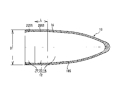
Figure 1 is a longitudinal section view of a plug 10
according to a first embodiment of the present invention.
As shown in Figure 1, the plug 10 includes a plug body 12,
and a sprayed film 16.
The plug body 12 includes a body 18, a columnar
portion 20, and a rear end portion 22.
The body 18 includes a front end portion of the plug
body 12. The body 18 has a circular cross section. The
diameter of the body 18 gradually becomes increased from
the front end to the rear end of the plug 10. The
diameter at the rear end of the body 18 is the maximum
diameter of the plug body 12.
The columnar portion 20 has the same diameter as
that of the rear end of the body 18, and extends from the
rear end of the body 18 in the axial direction of the
plug 10. Specifically, the columnar portion 20 has the
same diameter as the maximum diameter of the body 18. An
axial direction length L of the columnar portion 20 is 3
mm at least, for example.
If the front end of the body 18 is melted, the
columnar portion 20 is cut, and the body 18 is shifted
CA 02862099 2014-07-21
- 13 -
102-090-P1
rearward, so as to remove the melted portion. In this
case, the length of the columnar portion 20 becomes
reduced, but the shape and size of the body 18 is
regenerated to its original shape and size.
The rear end portion 22 extends from the rear end of
the columnar portion 20 in the axial direction of the
plug 10. The diameter of the rear end portion 22
gradually becomes reduced from the front end toward the
rear end of the plug 10.
[Protective film of plug body]
The sprayed film 16 is formed on the surface of the
above described plug body 12.
[Sprayed film]
The sprayed film 16 is formed on a surface 18S of
the body 18, and on a surface (side surface) 20SS of the
columnar portion 20. As shown in Figure 1, the sprayed
film 16 is formed not only on the surface 18S of the body
18 and the surface (side surface) 22SS of the columnar
portion 20, but also on a side surface 22SS of the rear
end portion 22.
The sprayed film 16 is formed by a well-known
spraying process such as an arc spraying, a plasma
spraying, a flame spraying, and a high-speed flame
spraying. The thickness of the sprayed film 16 is 400 gm
to 1200 pm, for example.
A shotblast may be applied to the surface of the
plug body 12 (the surface 18S of the body 18, the side
surface 20SS of the columnar portion 20, and the side
CA 02862099 2014-07-21
- 14 -
102-090-P1
surface 22SS of the rear end portion 22) on which the
sprayed film 16 is to be formed before the sprayed film
16 is formed. Through this configuration, the surface of
the plug body 12 becomes rough, and the adhesiveness of
the sprayed film 16 is enhanced.
The sprayed film 16 does not necessarily have a
constant thickness. For example, the front end of the
sprayed film 16 has a greater thickness than that of the
other portions thereof.
The chemical composition of the sprayed film 16 is
not limited to a specific one. The sprayed film 16
preferably contains iron (Fe) and iron oxide (such as
Fe304 and FeO) . In this case, the sprayed film 16 is
formed by arc-spraying an iron wire rod, for example.
The sprayed film 16 may further contain oxide other than
the iron oxide (such as tungsten oxide (W03)).
The percentage of the iron oxide in the sprayed film
16 formed of the iron and the iron oxide is preferably 55
to 80% by volume. The percentage of the iron oxide in
the sprayed film 16 is greater in portions of the sprayed
film 16 close to the surface of the sprayed film 16 than
in portions of the sprayed film 16 close to the body 18
and to the columnar portion 20, for example. In this
case, the percentage of the iron oxide in the sprayed
film 16 is 40% by volume at most at the boundary to the
plug body 12, and 55 to 80% by volume on the outer layer
of the sprayed film 16, for example. The percentage of
the iron oxide in the sprayed film 16 may be changed by
CA 02862099 2014-07-21
- 15 -
102-090-P1
changing a distance from a spray nozzle of an arc
spraying device to the plug body 12 (spraying distance),
for example.
Figure 2 is a schematic diagram showing a
configuration of a piercing machine 30 equipped with the
plug 10. In the piercing machine 30, the plug 10 is
attached to a front end of a mandrel 34, is disposed
between a pair of skew rolls 32, 32, and is located on a
pass line PL. A billet 36 is squeezed over the plug 10
during the piercing-rolling. At this time, the plug 10
is subjected to a high temperature and a high pressure.
The sprayed film 16 is formed on the surface of the
plug 10. The sprayed film has a hot strength greater
than that of the oxide scale. Hence, the plug 10 becomes
harder to be worn away than a plug, the surface on which
the oxide scale is formed. In other words, the usage
count of the plug 10 is enhanced.
The sprayed film 16 is preferably formed of the iron
and the iron oxide. In this configuration, the wear
resistance of the sprayed film 16 is enhanced.
The percentage of the iron oxide in the sprayed film
16 formed of the iron and the iron oxide is preferably
greater in portions of the sprayed film 16 close to the
surface of the sprayed film 16 than in the portions
thereof close to the body 18 and the columnar portion 20.
Through this configuration, the wear resistance of the
sprayed film 16 is further enhanced.
CA 02862099 2014-07-21
- 16 -
102-090-P1
As described above, the plug 10 is subjected to a
high temperature and a high pressure during piercing-
rolling of the billet 36. Consequently, repetitive usage
of the plug 10 may cause abrasion to the sprayed film 16,
and the melting loss at the front end portion of the plug
10.
[Regenerating method of plug]
The above described plug (plug used in the piercing-
roll: referred to as a used plug, hereinafter) can be
reused through the following regenerating method.
A used plug is first prepared (preparing step). The
used plug is then cut, and the body 18 is shifted more
rearward than its position before the cutting (cutting
step). In these steps, the melted portion of the front
end of the body 18 is removed, and the sprayed film 16 is
also removed. In the cutting step, the plug body 12 is
cut such that the original shape and size of the body 18
is maintained. At this time, the columnar portion 20 is
cut, and the rear end of the body 18 is shifted toward
the rear end of the columnar portion 20. As shown in
Figure 3A, the body 18 is regenerated into its original
shape and size, and the axial direction length L of the
columnar portion 20 is reduced to a length L'.
Thereafter, the shotblast is applied to the surface
of the plug body 12 (processing step). In this step, the
sprayed film 16 remaining on the surface of the plug body
12 is removed, and the surface of the plug body 12
becomes rough.
1
CA 02862099 2014-07-21
- 17 -
102-090-P1
A new sprayed film 16 is formed in the region where
the shotblast is applied (forming step). This means that
the sprayed film 16 is newly formed on the surface of the
plug body 12.
Through the above steps, a plug 101 shown in Figure
3B is produced. This plug 101 has a shorter axial
direction length of the columnar portion 20 compared to
that of the plug 10 shown in Figure 1, but the shape and
size of the body 18 is the same as those of the plug 10.
If the newly formed sprayed film 16 has the same
thickness as that of the previous sprayed film 16, the
maximum diameter of the plug 101 becomes equal to that of
the plug 10.
In the above regenerating method, it is possible to
produce the plug 101 that has the same shape and size of
the body 18 as those of the plug 10, and also has the
same maximum diameter D as that of the plug 10.
With respect to enhancement of the wear resistance
of the sprayed film 16, it is preferable that the sprayed
film 16 is formed of the iron and the iron oxide, and the
percentage of the iron oxide in the sprayed film 16 is
greater in portions of the sprayed film 16 close to the
surface of the sprayed film 16 than in the portions
thereof close to the body 18 and the columnar portion 20.
In this case, if a new sprayed film is formed on the worn
sprayed film, the percentage of the iron oxide in the
sprayed film 16 varies, that is, the percentage of the
iron oxide becomes different from the percentage of the
CA 02862099 2014-07-21
- 18 -
102-090-P1
iron oxide in the original sprayed film 16. Consequently,
the hot strength and the wear resistance of the sprayed
film 16 are deteriorated.
To the contrary, in the present embodiment, as
described above, the sprayed film 16 of the used plug is
completely removed, which equals the percentage of the
iron oxide between the newly formed sprayed film 16 and
the original sprayed film 16. Specifically, the
characteristics of the sprayed film 16 can be equal
before and after the regeneration of the plug.
If the body 18 is melted, the plug body 12 is cut,
and the body 18 is then shifted rearward. At this time,
the axial direction length of the columnar portion 20
becomes reduced in accordance with the rearward moved
distance of the body 18. This means that the plug can be
regenerated if the rearward moved distance of the body 18
is shorter than the axial direction length of the
columnar portion 20.
In the above described regenerating method, the
shotblast is applied on the surface of the plug body 12
after the cutting, but this shotblast may be omitted.
[Second embodiment]
Figure 4 is a longitudinal section view of a plug 50
according to a second embodiment of the present invention.
Compared to the plug 10, the plug 50 includes a plug body
12A instead of the plug body 12 (see Figure 1). The plug
50 further includes a build-up layer 14. The other
CA 02862099 2014-07-21
- 19 -
102-090-P1
elements of the plug 50 are the same as those of the plug
10.
[Plug body]
Compared to the plug body 12, the plug body 12A
includes a body 18A instead of the body 18 (see Figure 1).
The body 18A includes a first body portion 24 and a
second body portion 26.
The first body portion 24 includes a front end
portion of the plug body 12A. The first body portion 24
has a circular cross section. The first body portion 24
has a diameter gradually increased from the front end
toward the rear end of the plug 50.
The second body portion 26 has a greater diameter
than that of the rear end of the first body portion 24.
The second body portion 26 extends from the rear end of
the first body portion 24 in the axial direction of the
plug 50.
The second body portion 26 has a circular cross
section, and the front end of the second body portion 26
has a greater diameter than that of the rear end of the
first body portion 24. The second body portion 26 is
disposed coaxial with the first body portion 24.
Consequently, a step height is generated at the boundary
between the second body portion 26 and the first body
portion 24. A front end face 26FS of the second body
portion 26 is annular.
The second body portion 26 has a diameter gradually
increased from the front end toward the rear end of the
CA 02862099 2014-07-21
- 20 -
102-090-P1
plug 50. The diameter of the rear end of the second body
portion 26 is the maximum diameter of the plug body 12A.
The axial direction length Li of the columnar
portion 20 is shorter than the sum of the axial direction
length of a rolling portion A10 and the axial direction
length of a reeling portion A20 of the plug 50. The
rolling portion A10 takes charge of wall-thickness
rolling reduction, and the reeling portion A20 finishes
the wall thickness to be smooth.
If the front end of the plug 50, that is, the front
end of the build-up layer 14 is melted, the melted
portion is removed by reducing the axial direction length
of the columnar portion 20 and shifting the rear end of
the body 18A rearward. In this case, the columnar
portion 20 becomes reduced, but the shape and size of the
rolling portion A10 and the reeling portion A20 of the
plug 50 can be regenerated into its original shape and
size.
[Protective films of plug body]
Different protective films (the build-up layer 14
and the sprayed film 16) are formed in the front portion
and in the rear portion of the above described plug body
12A, respectively.
[Build-up layer]
The build-up layer 14 covers the circumference of
the body 18A. In the example of Figure 4, the build-up
layer 14 covers a surface 24S of the first body portion
CA 02862099 2014-07-21
- 21 -
102-090-P1
24. Specifically, in the example of Figure 4, the build-
up layer 14 covers the front end portion of the body 18A.
The build-up layer 14 is formed by a well-known
build-up welding process such as a plasma transferred arc
(PTA) welding, an MIG (metal inert gas) welding, and a
TIG (tungsten insert gas) welding.
The build-up layer 14 has a thickness of 1 mm at
least, for example. Preferably, the build-up layer 14
has a thickness of 1 to 20 mm, and more preferably 2 to
mm. If the thickness is to exceed 5 mm, a plurality
of build-up layers may be formed, for example. Each
layer has a thickness of 2 to 5 mm, for example. After a
plurality of build-up layers are formed, the target
entire thickness may be achieved by cutting away the
surface of the topmost build-up layer. If the thickness
is to be smaller than 2 mm, a build-up layer with a
thickness of 2 mm or larger may be formed before the
surface of the build-up layer is cut away to achieve the
target thickness. If the build-up layer 14 is too thin,
the hot strength may not be improved. If the build-up
layer 14 is too thick, the build-up layer 14 may develop
a crack. Moreover, forming such a build-up layer 14 may
require a longer time, leading to increased manufacturing
costs. The build-up layer 14 does not necessarily have a
constant thickness. The thickness of the build-up layer
14 may be greater at the front end portion than that in
the other portions thereof, for example.
CA 02862099 2014-07-21
- 22 -
102-090-P1
In the example of Figure 4, a thickness L2 of the
front end portion of the build-up layer 14 is equal to
the axial direction length Li of the columnar portion 20
at most. In this configuration, such a problem can be
avoided that the rear end of the body 18A cannot be
shifted rearward if the melted portion of the build-up
layer 14 is removed.
The diameter of the rear end of the build-up layer
14 is greater than the diameter of the front end of the
second body portion 26.
The build-up layer 14 is formed of an alloy mainly
containing a transition metal, for example. This alloy
is an alloy (stellite alloy) containing cobalt (Co) as a
main component, along with chrome (Cr) and tungsten (W),
for example.
The build-up layer 14 may contain carbide of a
transition metal. The carbide of the transition metal
may be niobium carbide (NbC), tungsten carbide (WC),
titanium carbide (TiC), vanadium carbide (VC), and
chromium carbide (CrC), etc. The carbide of the
transition metal of 20 to 50% by volume may be contained,
for example. The average grain diameter of the carbide
of the transition metal is 65 to 135 pm, for example.
[Sprayed film]
The sprayed film 16 is formed on the surface of the
body 18A in the regions other than a region where the
build-up layer 14 is formed, and on the surface of the
columnar portion 20. In the example of Figure 4, the
CA 02862099 2014-07-21
- 23 -
102-090-P1
sprayed film 16 is formed on a side surface 26SS of the
second body portion 26, a side surface 20SS of the
columnar portion 20, and a side surface 22SS of the rear
end portion 22. In the present embodiment, the thickness
of the sprayed film 16 is 400 pm to 800 tm, for example.
In the example of Figure 4, the diameter of the
front end of the sprayed film 16 is equal to the diameter
of the rear end of the build-up layer 14. Specifically,
the surface of the build-up layer 14 is smoothly combined
with the surface of the sprayed film 16.
The plug 50 shown in Figure 4 is for use in the
piercing machine 30 shown in Figure 2. The billet 36 is
squeezed over the plug 50 during the piercing-rolling.
Consequently, the plug 50 is subjected to a high
temperature as well as a high pressure.
The front end portion of the plug 50 is covered with
the build-up layer 14. In the example of Figure 4, the
first body portion 24 and the build-up layer 14 covering
the surface of the first body portion 24 agree with the
rolling portion A10. This means that the surface of the
rolling portion A10 is constituted by the build-up layer
14. The build-up layer has a higher hot strength than
that of the sprayed film and the oxide scale.
Accordingly, the rolling portion A10 including the front
end portion of the plug 50 becomes unlikely to be melted
even if the billet 36 is piercing-rolled with the rolling
portion A10.
CA 02862099 2014-07-21
- 24 -
102-090-P1
In the example of Figure 4, the first body portion
24 and the build-up layer 14 covering the surface of the
first body portion 24 agrees with the rolling portion A10,
but this may be unnecessary. The build-up layer 14 may
be formed on a portion to be easily melted during the
piercing-rolling of the billet. The rolling portion is
likely to be melted, and the melting loss is likely to be
generated particularly at the front end portion of the
rolling portion, and in regions of the rolling portion
that oppose gorging portions 321 of the skew rolls 32
(portions opposing the gorging portions in the direction
perpendicular to the pass line PL). As shown in Figure 5,
the distance between the pair of skew rolls 32, 32
becomes the smallest at a position between the gorging
portions 321, 321 (a position GL indicated by a dashed
line in Figure 5). In general, melting loss is likely to
occur in a width WP extending several centimeters
frontward and rearward (extending 3 cm frontward and
rearward, respectively, for example) along the pass line
direction from the position GL of the rolling portion
that opposes the gorging portions 321. Accordingly, the
build-up layer 14 is preferably formed at least in a
region from the front end of the plug to a position more
rearward by a predetermined distance (3 cm, for example)
than the position GL. No build-up layer 14 is preferably
formed on the reeling portion A20 for the purpose of
preventing the scoring of the plug.
CA 02862099 2014-07-21
- 25 -
102-090-P1
The sprayed film 16 is formed on the side surface
other than the rolling portion A10 of the plug 50. This
sprayed film has a greater scoring resistance than that
of the build-up layer. Accordingly, the plug 50 is more
unlikely to be scored compared to the case of covering
the entire surface of the plug body 12A with the build-up
layer.
As described above, in the plug 50, the build-up
layer reduces the melting loss at the front end portion,
and the sprayed film reduces the scoring. Accordingly,
the life of the plug 50 becomes enhanced.
In general, the build-up layer is configured to have
a greater thickness than that of the sprayed film. In
the plug 50, the plug body 12A includes the first body
portion 24 and the second body portion 26. The diameter
at the rear end of the first body portion 24 is smaller
than the diameter at the front end of the second body
portion 26. Consequently, no step height is generated at
the boundary between the surface of the build-up layer 14
and the surface of the sprayed film 16, so that the
surface of the build-up layer 14 is smoothly combined
with the surface of the sprayed film 16 in the plug 50.
Accordingly, flaws are unlikely to be generated on an
internal surface of a hollow shell obtained by piercing-
rolling of the billet 36.
As described above, the plug 50 is subjected to a
high temperature and a high pressure during the piercing-
rolling of the billet 36. Hence, repetitive usage of the
CA 02862099 2014-07-21
- 26 -
102-090-P1
plug 50 may cause an abrasion to the sprayed film 16, or
cause the melting loss at the front end portion of the
build-up layer 14.
[Regenerating method of plug]
The above described plug (plug used in the piercing-
rolling: referred to as a used plug, hereinafter) can be
reused through the following regenerating method.
A used plug is first prepared (preparing step). If
the front end of the build-up layer 14 is not melted, the
sprayed film 16 remaining on the surface of the used plug
is removed (removing step). Specifically, the shotblast
is applied to regions on the surface of the used plug
other than a region where the build-up layer 14 is formed.
In this step, the sprayed film 16 remaining on the
surface of the used plug is removed, and the regions on
the surface of the plug body 12A other than the region
where the build-up layer 14 is formed become rough.
Figure 6A shows the plug (the plug body 12A and the
build-up layer 14) from which the sprayed film 16 is
removed.
Subsequently, a new sprayed film 16 is formed in the
region where the shotblast is applied (forming step).
This means that the sprayed film 16 is newly formed on
the surface of the plug body 12A in the regions other
than the region where the build-up layer 14 is formed.
Through the above steps, the plug 50 shown in Figure 4 is
produced.
CA 02862099 2014-07-21
- 27 -
102-090-P1
If the build-up layer 14 is melted, the used plug is
cut, and the rear end of the body 18A is shifted more
rearward than its position before the plug is cut
(cutting step). In this step, the melted portion at the
front end of the build-up layer 14 is removed, and the
sprayed film 16 is also removed. In the cutting step,
the used plug is cut such that the shape and size of the
rolling portion A10 and the reeling portion A20 at the
time of forming the new sprayed film 16 is maintained to
be the original shape and size thereof. At this time,
the columnar portion 20 becomes reduced, and the rear end
of the body 18A is shifted toward the rear end of the
columnar portion 20 (see Figure 6B). The variation in
the axial direction length of the columnar portion 20
(Ll-L1') is equal to the variation in thickness of the
front end portion of the build-up layer 14 (L2-L2').
Thereafter, the shotblast is applied to the regions
on the surface of the plug body 12A other than the region
where the build-up layer 14 is formed (processing step).
In this step, the sprayed film 16 remaining on the
surface of the used plug is removed, and the regions on
the surface of the plug body 12A other than the region
where the build-up layer 14 is formed become rough.
Subsequently, the sprayed film 16 is newly formed in
the region where the shotblast is applied (forming step).
Specifically, the sprayed film 16 is newly formed on the
surface of the plug body 12A in the regions other than
the region where the build-up layer 14 is formed. In
CA 02862099 2014-07-21
- 28 -
102-090-P1
this step, a plug 500 shown in Figure 6C is produced.
This plug 500 has a shorter axial direction length of the
columnar portion 20 compared to that of the plug 50 shown
in Figure 4, but the shape and size of the rolling
portion A10 and the reeling portion A20 is the same as
those of the plug 50.
In the above regenerating method, it is possible to
produce the plug 50 and 500 each of which has the same
shape and size of the rolling portion A10 and the reeling
portion A20 as well as the same maximum diameter D by
equalizing the thickness of the newly formed sprayed film
16 to the thickness of the original sprayed film 16.
At the time of removing the melted portion of the
build-up layer 14, the axial direction length of the
columnar portion 20 becomes reduced in accordance with
the rearward moved distance of the rear end of the second
body portion 26 (body 18A). This means that the plug can
be regenerated if the rearward moved distance of the rear
end of the body 18A is shorter than the axial direction
length of the columnar portion 20.
If the thickness L2 of the front end portion of the
build-up layer 14 is greater than the axial direction
length Li of the columnar portion 20, the plug 50 may be
regenerated immediately before the build-up layer 14
becomes lost. Therefore, the number of regeneration of
the plug 50 is increased.
In the above described regenerating method, the
shotblast is applied to the regions on the surface of the
CA 02862099 2014-07-21
- 29 -
102-090-P1
plug body 12A other than the region where the build-up
layer 14 is formed after the used plug is cut, but this
shotblast may be omitted.
[Third embodiment]
The plug according to an embodiment of the present
invention may be configured in any manner as far as the
build-up layer is formed on the surface of the body. An
example of this is shown in Figure 7.
Figure 7 shows a plug 70 according to a third
embodiment of the present invention. The plug 70
includes a plug body 12B instead of the plug body 12A.
The plug body 12B includes a body 183 instead of the body
18A. The body 18B further includes a projection 28 as
well as the first body portion 24 and the second body
portion 26. The projection 28 is adjacently disposed in
front of the first body portion 24. The diameter of the
rear end of the projection 28 is greater than the
diameter of the front end of the first body portion 24.
Consequently, a groove is formed on the side surface of
the plug body 12B between the projection 28 and the
second body portion 26 in the circumferential direction.
In present embodiment, the build-up layer 14 is formed in
this groove. A sprayed film 29 is formed on the surface
of the projection 28. The thickness of the sprayed film
29 is 1200 gm, for example.
In the plug 70, the projection 28 is covered with
the sprayed film 29. The sprayed film 29 has a wear
CA 02862099 2014-07-21
- 30 -
102-090-P1
resistance more excellent than that of the oxide scale.
Accordingly, the usage count of the plug 70 is enhanced.
Even if the sprayed film 29 is worn away, a new
sprayed film 29 is formed on the plug after the worn
sprayed film 29 is removed, thereby regenerating the plug
70. In other words, the plug 70 can be maintained to
stay usable.
The billet for use in the piercing-rolling by using
the plug 70 may be solid or hollow. That is, the plug 70
may be used for an elongator (second piercing machine).
In other words, piercing machines for which the plug 70
may be used include elongators. If a hollow billet is
used in the piercing-rolling, the sprayed film 29 may not
be formed.
[Example 1]
[Plug]
There were prepared a plug configured shown in
Figure 1 (inventive example) and a plug configured shown
in Figure 8 (comparative example).
In each plug of the inventive example, the maximum
diameter D was 147 mm, the axial direction length of the
columnar portion 20 was 12 mm. The sprayed film 16 was
formed of the iron and the iron oxide, and was formed by
arc-welding an iron wire in the same condition. The
content by percentage of the iron oxide in the sprayed
film was 20% by volume at the boundary to the plug body,
and 70% by volume in the outer layer. The thickness of
CA 02862099 2014-07-21
- 31 -
102-090-P1
the sprayed film was 1200 lam in the front end portion,
and 400 m in the other portions.
In the plug of the comparative example, an oxide
scale 121 was formed on the surface of the plug body 12.
In this plug, the maximum diameter D was 147 mm, and the
axial direction length of the columnar portion 20 was 12
mm. The thickness of the oxide scale was approximately
400 m.
[Test method]
Billets were piercing-rolled by using the above
plugs, and thereafter, variation at the front end, and
reduction of the maximum diameter were measured for each
plug. Each billet was made of 13 Cr steel, the diameter
was 191 mm, and the length was 3000 mm.
In the plug of the inventive example, the variation
at the front end and the reduction of the maximum
diameter were measured after the piercing-rolling of the
first billet, and after the piercing-rolling of the third
billet. In the plug of the comparative example, the
variation at the front end, and the reduction of the
maximum diameter were measured after the piercing-rolling
of the first billet.
[Test results]
The test results are shown in Figure 9 and Figure 10.
As shown in Figure 9, in the plug of the inventive
example, the variation at the front end was smaller even
after three counts of the piercing pass compared to the
plug of the comparative example (count of piercing pass:
CA 02862099 2014-07-21
- 32 -
102-090-P1
1). As shown in Figure 10, the plug of the inventive
example had a smaller reduction of the maximum diameter
even after three counts of the piercing pass compared to
the plug of the comparative example (count of piercing
pass: 1).
[Example 2]
There were prepared plugs of the test numbers 1 to 6
as shown in Table 1.
[Table 1]
TABLE 1
-
=
Axial Direction Length of Columnar Axial Direction Length of Cd um nar Axial
Direction Length of Columnar Axial Direction Length of Columnar Axial
Direction Length of Columnar
Test Portion: 12 mm Portion: 9 mm Portion: 6 mm Portion: 3 mm
Portion: 0 mm Total Count Ratio of
. .
number Count Ratio of Count Ratio
ofCount Ratio of - Count Ratio of Count Ratio of Piercing Pass
Regeneration Regeneration Regeneration Regeneration
Regeneration
Piercing Pass Piercing Pass Piercing Pass = Piercing Pass
Piercing Pass
, ,
1 , 7.0 Regeneratable 7.5 Regeneratable 8.0 .
Regeneratable 7.0 Regeneratable 8.0 Regeneratable 37.5
2 6.5 Regeneratable 7.5 Regeneratable 8.0
Regeneratable , 7.5 , Regeneratable 8.0 Regeneratable 37.5
3 6.5 Regeneratable 7.5 Regeneratable 7.5 _
Regeneratable . 7.0 Regeneratable 8.0 Regeneratable 36.5
4 7.0 Regeneratable 7.5 Regeneratable 7.0
Regeneratable _ 7.0 Regeneratable 8.0 Regeneratable 36.5
7.0 Regeneratable 7.5 Regeneratable 7.5 Regeneratable
7.5 Regeneratable 7.5 Regeneratable 37.0
6 1.0 Regeneratable _ 1.0 _ Unregeneratable _----- ___
_____------- ---- -
-
---------- 2.0
P
.
IV
00
01
IV
I ,T,
l0
W I,,'
CA)
I I,
I
"
I-I
I-I
CD
I\ )
I
CD
.C1
CI
I
IT,
I-I
CA 02862099 2014-07-21
- 34 -
102-090-P1
[Plug]
In each plug of the test numbers 1 to 5, the sprayed
film 16 was formed on the surface of the plug body 12 as
shown in Figure 1. In each plug, the maximum diameter D
was 147 mm, and the axial direction length of the
columnar portion 20 was 12 mm. The sprayed film 16 was
formed of the iron and the iron oxide, and was formed by
arc-welding the iron wire in the same condition. The
content by percentage of the iron oxide in the sprayed
film was 20% by volume at the boundary to the plug body,
and 70% by volume in the outer layer. The thickness of
the sprayed film was 1200 m in the front end portion,
and 400 m in the other portions.
In the plug of the test number 6, as shown in Figure
8, the oxide scale 121 was formed on the entire surface
of the plug body 12. In this plug, the maximum diameter
D was 147 mm, and the axial direction length of the
columnar portion 20 was 12 mm. The thickness of the
oxide scale was approximately 400 m.
[Test method]
Billets were piercing-rolled by using the plugs in
the test numbers 1 to 6, and thereafter, variation at the
front end, and reduction of the maximum diameter were
measured for each plug. Each billet was made of 13 Cr
steel, the diameter was 191 mm, and the length was 2200
rum.
The piercing-rolling was repetitively performed to
the billet until the variation at the front end, that is,
CA 02862099 2014-07-21
- 35 -
102-090-P1
the melting loss (reduction of the plug in the axial
direction) became 2.5 mm to 3.0 mm, or until the
reduction of the maximum diameter became 0.5 to 0.8 mm
(until the plug regenerating condition was satisfied), so
as to evaluate the count of the piercing pass for each
plug.
The count of the piercing pass was evaluated based
on the count ratio of the piercing pass. This count
ratio of the piercing pass was a ratio relative to the
count of the piercing pass for the plug having the oxide
scale formed on its surface (test number 6), which was
defined as 1.
If the plug regenerating condition was satisfied,
each plug was regenerated in accordance with the above
described regenerating method. In each regeneration, the
axial direction length of the columnar portion was
reduced by 3 mm from the previous axial direction length.
The same sprayed film and the same oxide scale were
formed.
The regenerated plugs were used, and the above
described test was repetitively conducted on those plugs
until their columnar portions were lost.
[Test results]
Table 1 shows the test results. The count ratio of
the piercing pass when the plug of the test number 6
became unusable (i.e. when the axial direction length of
the columnar portion of each plug became 6 mm, 3 mm, and
0 mm) was a ratio relative to the count of the piercing
CA 02862099 2014-07-21
- 36 -
102-090-P1
pass for the plug of the test number 6 having the axial
direction length of the columnar portion of 12 mm, which
was defined as 1. The total count ratio of the piercing
pass was a sum of the count ratios of the piercing pass
for the plug of each test number.
In each plug of the test numbers 1 to 5, the count
ratio of the piercing pass until the plug regenerating
condition was satisfied was 6.5 at least, which was
higher than the count ratio of the piercing pass for the
plug of the test number 6. The plugs of the test numbers
1 to 5 could be regenerated four times. The total count
ratio of the piercing pass for each plug of the test
numbers 1 to 5 was 36.5 at least, which was higher than
that for the plug of the test number 6.
To the contrary, in the test number 6, the reduction
of the maximum diameter of the plug after repeating the
test (i.e., piercing-rolling) was significant, and the
plug could be regenerated only once. The oxide scale is
generated by oxidizing the surface of the plug base
metal; thus the wear of the oxide scale causes reduction
of the maximum diameter of the plug base metal.
Consequently, in the test number 6, the plug could be
regenerated only once although the columnar portion of
this plug still remained. Specifically, the reduction of
the maximum diameter of the plug was so significant that
the plug became unusable as the plug having the same size
any more.
[Example 3]
CA 02862099 2014-07-21
- 37 -
102-090-P1
[Plug]
There were prepared a plug configured shown in
Figure 4 (inventive example 1), a plug configured shown
in Figure 1 (inventive example 2), and a plug configured
shown in Figure 8 (comparative example).
In the plug of the inventive example 1, the maximum
diameter D was 147 mm, and the axial direction length of
the columnar portion 20 was 12 mm. The build-up layer 14
was formed by the PTA process, and was formed of a
stellite 6 alloy containing NbC of 50% by mass. The
thickness of the build-up layer was 7 mm. The sprayed
film 16 was formed of the iron and the iron oxide, and
was formed by arc-welding the iron wire in the same
condition. The content by percentage of the iron oxide
in the sprayed film was 20% by volume at the boundary to
the plug body, and 70% by volume in the outer layer. The
thickness of the sprayed film was 400 pm.
In the plug of the inventive example 2, the sprayed
film 16 was formed on the surface of the plug body 12.
The axial direction length of the columnar portion 20 was
12 mm. The maximum diameter D of the plug was 147 mm.
The sprayed film was formed of the iron and the iron
oxide, and was formed by arc-welding the iron wire in the
same condition. The content by percentage of the iron
oxide in the sprayed film was 20% by volume at the
boundary to the plug body, and 70% by volume in the outer
layer. The thickness of the sprayed film was 1200 gm in
CA 02862099 2014-07-21
- 38 -
102-090-P1
the front end portion, and 400 pm in the other portions
of the plug.
In the plug of the comparative example, the oxide
scale 121 was formed on the surface of the plug body 12.
The axial direction length of the columnar portion 20 was
12 mm. The maximum diameter D of the plug was 147 mm.
The thickness of the oxide scale was approximately 400 Rm.
[Test method]
Billets were piercing-rolled by using these plugs,
and thereafter, variation at the front end, and reduction
of the maximum diameter were measured for each plug.
Each billet was formed of 13 Cr steel, the diameter was
191 mm, and the length was 3000 mm.
In the plug of the inventive example 1, the
variation at the front end, and the reduction of the
maximum diameter were measured after the piercing-rolling
of the fifth billet. In the plug of the inventive
example 2, the variation at the front end, and the
reduction of the maximum diameter were measured after the
piercing-rolling of the first billet, and after the
piercing-rolling of the third billet. In the plug of the
comparative example, the variation at the front end, and
the reduction of the maximum diameter were measured after
the piercing-rolling of the first billet.
[Test results]
The test results are shown in Figure 11 and Figure
12. As shown in Figure 11, in the plug of the inventive
example 1, the variation at the front end was smaller
i
CA 02862099 2014-07-21
- 39 -
102-090-P1
even after the five counts of the piercing pass, compared
to the plug of the inventive example 2 and the plug of
the comparative example. As shown in Figure 12, in the
plug of the inventive example 1, the reduction of the
maximum diameter was smaller than the plug of the
comparative example even after the five counts of the
piercing pass. As shown in Figure 12, in the plug of the
inventive example 2, the reduction of the maximum
diameter was smaller than the plug of the comparative
example even after the three counts of the piercing pass.
[Example 4]
There were prepared plugs of the test numbers 1 to 4
as shown in Table 2.
[Table 2]
,
70 TABLE 2
Axial Direction Length of Columnar Axial Direction Length of Columnar Axial
Direction Length of Columnar
Test Portion: 12 mm Portion: 9 mm
Portion: 6 mm Total Count Ratio of
r-h
I-1 number Count Ratio ofCount Ratio of Count Ratio
of Piercing Pass
= M Regeneration
Regeneration Regeneration
m Piercing Pass Piercing Pass Piercing
Pass
'
I--'
o 1 15.0 Regeneratable 14.5
Regeneratable 15.5 Regeneratable 45.0
= LQ 2 9.5 Regeneratable 10.5
Regeneratable 10.0 Regeneratable 30.0
,
Ft- o
1-h 3 9.0 Regeneratable 7.0 Regeneratable 8.0
Regeneratable 24.0
CD
---
rt 4 1.0 Regeneratable 1.0 Unregeneratable
_------ ___------ 2.0
Ci)
P
M
0
I-1
Iv
I-h Ci
0
0
P) M
Iv
I
0
c) (J)
.
a) rt
.
"
o .
o
I
Ø7
i-h
rr
"
(1)
,
CD I-1
i-h 1-
1-' '
I-1
0) (-
CI-
CD
t:r
o t3-
a
I--'
1.0 Q-'
0
ii 0cp
rr '0
(.)
O
1-' 0
=
Di LO
1-<
0
I
ND (1)
11:1
.A I-1
.
..
CA 02862099 2014-07-21
- 41 -
102-090-P1
and the sprayed film 16 was formed on the other portions
(the second body portion 26, the columnar portion 20, and
the rear end portion 22), as shown in Figure 4. In the
plug of the test number 2, the build-up layer was formed
on the surface of the first body portion 24, and the
sprayed film 16 was formed on the other portions (the
projection 28, the second body portion 26, the columnar
portion 20, and the rear end portion 22), as shown in
Figure 7. In each plug, the axial direction length of
the columnar portion 20 was 12 mm. The maximum diameter
D of each plug was 147 mm. The build-up layer 14 was
formed by the PTA process. The build-up layer was formed
of a stellite 6 alloy containing NbC of 50% by mass. The
thickness of the build-up layer was 7 mm. Each sprayed
film 16 of the test numbers 1 and 2 was formed of the
iron and the iron oxide, and was formed by arc-welding
the iron wire in the same condition. The content by
percentage of the iron oxide in the sprayed film was 20%
by volume at the boundary to the plug body, and 70% by
volume in the outer layer. The thickness of the sprayed
film of the test number 1 was 400 m. The thickness of
the sprayed film of the test number 2 was 1200 m in the
front end portion, and 400 m in the other portions.
In the plug of the test number 3, the sprayed film
16 was formed on the surface of the plug body 12, as
shown in Figure 1. In this plug, the axial direction
length of the columnar portion 20 was 12 mm. The maximum
diameter D of the plug was 147 mm. The sprayed film 16
CA 02862099 2014-07-21
- 42 -
102-090-P1
was formed of the iron and the iron oxide, and was formed
by arc-welding the iron wire in the same condition. The
content by percentage of the iron oxide in the sprayed
film was 20% by volume at the boundary to the plug body,
and 70% by volume in the outer layer. The thickness of
the sprayed film was 1200 gm in the front end portion,
and 400 gm in the other portions.
In the plug of the test number 4, the oxide scale
121 was formed on the surface of the plug body 12, as
shown in Figure 8. In this plug, the axial direction
length of the columnar portion 20 was 12 mm. The maximum
diameter D of the plug was 147 mm. The thickness of the
oxide scale 121 was approximately 400 pm.
[Test method]
Billets were piercing-rolled by using the plugs of
the test numbers 1 to 4, and thereafter, variation at the
front end, and reduction of the maximum diameter were
measured for each plug. Each billet was formed of 13 Cr
steel, the diameter was 191 mm, and the length was 2200
mm.
The piercing-roll of billets was repetitively
performed until the variation at the front end, that is,
the melting loss (reduction of the plug in the axial
direction) became 2.5 mm to 3.0 mm, or until the
reduction of the maximum diameter became 0.5 to 0.8 mm
(until the plug regenerating condition was satisfied), so
as to evaluate the count of the piercing pass for each
plug.
CA 02862099 2014-07-21
- 43 -
102-090-P1
The count of the piercing pass was evaluated based
on the count ratio of the piercing pass. This count
ratio of the piercing pass was a ratio relative to the
count of the piercing pass for the plug having the oxide
scale formed on its surface (test number 4) until the
regeneration was necessary for this plug, which was
defined as 1.
If the plug regenerating condition was satisfied,
each plug was regenerated in accordance with the above
described regenerating method. At this time, the axial
direction length of the columnar portion was reduced by 3
mm from the previous axial direction length. The same
sprayed films and oxide scales were formed.
The regenerated plugs were used, and the above
described test was repetitively conducted on those plugs.
The regeneration of each plug was conducted until the
axial direction length of its columnar portion became to
be 6 mm.
[Test results]
The test results are shown in Table 2. The count
ratio of the piercing pass when the plug of the test
number 4 became unusable (i.e., when the axial direction
length of the columnar portion of each plug became 6 mm)
was a ratio relative to the count of the piercing pass
for the plug of the test number 4 having the axial
direction length of the columnar portion of 12 mm, which
was defined as 1. The total count ratio of the piercing
CA 02862099 2014-07-21
- 44 -
102-090-P1
pass was a sum of the count ratios of the piercing pass
for the plug of each test number.
In each plug of the test numbers 1 and 2, the count
ratio of the piercing pass until the plug regenerating
condition was satisfied was 9.5 at least, which was
higher than the count ratio of the piercing pass in each
plug of the test numbers 3 and 4. In the test numbers 1
and 2, the plug could be regenerated twice. In each plug
of the test numbers 1 and 2, the total count ratio of the
piercing pass was 30.0 at least, which was higher than
the total count ratio of the piercing pass in each plug
of the test numbers 3 and 4. In the plug of the test
number 3, the count ratio of the piercing pass until the
plug regenerating condition was satisfied was 7.0 at
least, which was smaller than those in the test numbers 1
and 2, but higher than that in the test number 4. In the
test number 3, the plug could be regenerated twice. In
the test number 3, the total count ratio of the piercing
pass was 24.0 at least, which was smaller than those in
the test numbers 1 and 2, but higher than that in the
test number 4. In the test number 4, the reduction of
the maximum diameter of the plug having experienced
repeating the test (i.e., piercing-rolling) was
significant, and the plug could be regenerated only once.
The oxide scale is generated by oxidizing the surface of
the plug base metal; thus the wear of the oxide scale
reduces the maximum diameter of the plug base metal.
Consequently, the plug in the test number 4 could be
CA 02862099 2014-07-21
- 45 -
102-090-P1
regenerated only once although the columnar portion of
this plug still remained. Specifically, the reduction of
the maximum diameter of the plug was so significant that
the plug could not be used as the plug having the same
size any more.
The embodiments of the present invention have been
described in detail, but these are merely examples of the
present invention, and the present invention is not
limited by the above described embodiments.