Note: Descriptions are shown in the official language in which they were submitted.
CA 02862197 2014-07-22
WO 2013/112089 PCT/SE2012/050629
1
USER EQUIPMENT, NETWORK NODE AND METHOD FOR APPLYING POWER
SCALING TO UPLINK TRANSMISSIONS
TECHNICAL FIELD
Embodiments herein relate to a user equipment, a network node and methods
therein. In particular, some embodiments herein relate to apply power scaling
to uplink
transmissions in a multiple cell communications network.
BACKGROUND
In today's radio communications networks a number of different technologies
are
used, such as Long Term Evolution (LTE), LTE-Advanced, Wideband Code Division
Multiple Access (WCDMA), Global System for Mobile communications/Enhanced Data
rate for GSM Evolution (GSM/EDGE), Worldwide lnteroperability for Microwave
Access
(WiMax), or Ultra Mobile Broadband (UMB), just to mention a few possible
implementations. A radio communications network comprises radio base stations
providing radio coverage over at least one respective geographical area
forming a cell.
The cell definition may also incorporate frequency bands used for
transmissions, which
means that two different cells may cover the same geographical area but using
different
frequency bands. User equipments (UE) are served in the cells by a respective
radio base
station, also called e.g. eNodeB (eNB), and are communicating with the
respective radio
base station. The user equipments transmit data over an air or radio interface
to the radio
base stations in uplink (UL) transmissions and the radio base stations
transmit data over
an air or radio interface to the user equipments in downlink (DL)
transmissions.
LTE uses Discrete Fourier Transform- Spread- Orthogonal Frequency Division
Multiplexing (DFTS-OFDM) or Single Carrier-Frequency Division Multiple-Access
(SC-
FDMA) in the uplink. In the time-domain the time-axis is divided into
subframes of 1 ms
and each subframe is divided into 12, using long cyclic prefix, or 14, using
normal cyclic
prefix, SC-FDMA symbols.
Data is transmitted on Physical Uplink Shared Channel (PUSCH). Bits are
encoded, interleaved, scrambled, and transmitted via the SC-FDMA modulator. In
the
receiver an inverse process happens. During the demodulation the receiver
typically
calculates soft values or soft bits, one for each information bit or sometimes
even one for
each coded bit, which correspond to likelihoods that a bit is zero or one.
CA 02862197 2014-07-22
WO 2013/112089 PCT/SE2012/050629
2
Another UL channel is the control channel Physical Uplink Control Channel
(PUCCH). PUCCH applies block spreading, i.e. information is spread with
spreading
sequences over multiple SC-FDMA symbols. This improves coverage since
information is
transmitted with more energy but also enables multiplexing with others using
the same
time-frequency resources but different spreading sequences. To make different
transmissions orthogonal, not interfering with one another, the repetitions
must be done
with the same power; the copy in different SC-FDMA symbol must be transmitted
with the
same power. If certain SC-FDMA symbols are transmitted with different power
orthogonality is impaired.
Sounding Reference Signals (SRS) are UL reference signals that give the eNB,
radio base station in LTE is mostly denoted eNB or eNodeB, information about
UL
channel state. SRSs are transmitted within the last SC-FDMA symbol of a
subframe.
In LTE, transmissions from different user equipments may be multiplexed into
the
same SC-FDMA symbol using different frequencies. To maintain orthogonality
among
user equipments it is important that the UL signals from different user
equipments arrive
time-aligned at the UL receiver.
Since user equipments may be located at different distances from the eNB, as
shown in Figure 1, the user equipments will need to initiate their UL
transmissions at
different times. Figure 1 is an Illustration of two user equipments at
different distance from
the eNB. A user equipment far from the eNB, called Cell edge UE, needs to
start
transmission earlier than a user equipment close to the eNodeB. This can for
example be
handled by timing advance of the UL transmissions, which means that a user
equipment
starts its UL transmission before a nominal time given by the timing of the DL
signal
received by the user equipment. This concept is illustrated in Figure 2, which
shows
timing advance of UL transmissions from the user equipment depending on
distance to
the eNB. A DL transmission transmitted at time TO from the eNodeB is received
by the UE
close to the eNodeB at T1. The same transmission is received at the cell edge
UE at T2.
For the eNodeB to receive all UL transmissions simultaneously after the
transmission of
the DL packet, the Cell edge UE is transmitting the UL transmission with a
timing advance
1. The UE close to the eNodeB is transmitting UL transmission with a timing
advance 2.
The UL Timing Advance (TA) is maintained by the eNodeB through TA commands
sent to the user equipment based on measurements on UL transmissions from that
user
equipment. Through TA commands, the user equipment is ordered to start its UL
transmissions earlier or later. This applies to all UL transmissions except
for random
access preamble transmissions on Physical Random Access Channel (PRACH).
CA 02862197 2014-07-22
WO 2013/112089 PCT/SE2012/050629
3
LTE Release-10 specifications have recently been standardized, supporting cell
bandwidths up to 20 MHz, which is the maximal LTE Release-8 bandwidth. An LTE
Release-10 operation wider than 20 MHz is possible and appear as a number of
LTE cells
to an LTE Release-10 user equipment.
In particular for early LTE Release-10 deployments it can be expected that
there
will be a smaller number of LTE Release-10-capable user equipments compared to
many
LTE legacy user equipments. Therefore, it is necessary to assure an efficient
use of a
wide carrier also for legacy user equipment, i.e. that it is possible to
implement carriers
where legacy user equipments may be scheduled in all parts of the wideband LTE
Release-10 carrier. The straightforward way to obtain this would be by means
of Carrier
Aggregation (CA). CA implies that an LTE Release-10 user equipment may receive
multiple cells or carriers, where the cells have, or at least the possibility
to have, the same
structure as a Release-8 cell. CA is illustrated in Figure 3. Cell 1 or as
referred to in the
Figure 3 Component Carrier 1 (CC1) has a TA1 with reference to TA=O. Cell 2 or
as
referred to in the Figure 3 Component Carrier 2 (CC2) has a TA2 with reference
to TA=O.
Cell 3 or as referred to in the Figure 3 Component Carrier 3 (CC3) has a TA3
with
reference to TA=O. In this example all TA are measured towards the same timing
reference TA=O, in a more general setup all TA could be measured against
different
timing references. It is also illustrated that different subframes over the
different cells are
transmitted with different levels of transmit power or transmission power.
Time is defined
along a horizontal axis and power is defined along a vertical axis.
To support scenarios where different UL cells, also referred to as carriers,
are
received at geographical different locations or frequency selective UL
repeaters multiple
TA values are required. The eNB must be able to control the UL reception
timing of each
cell to maintain orthogonality on each cell. Thus, multiple TAs may be needed
to control
them individually. Since the TA value controls the UL transmission timings
different TA
values imply misaligned UL subframes, see Figure 3.
The end and beginning of subframes on the individual cells are determined by
the
TA commands; TA1 to TA3 for cell Component Carrier 1 (CC1) to Component
Carrier 3
(CC3), respectively, in Figure 3. Since the eNB knows the TA commands it also
knows
the end and beginning of subframes. Due to different TA values UL subframes
are not
time aligned. In the transition period from subframe n+1 to n + 2 the
requested power
exceeds the available transmit power since cell CC3 requests higher power but
the other
two cells have not yet reduced their transmit power. Since the overall signal
transmitted
by the UE cannot exceed the maximum power, the signal power will be limited by
the
CA 02862197 2014-07-22
PCT/SE 2012/050 629 - 22-11-2013
P313498W01
=
4
power amplifier which can lead to unpredictable effects, e.g. the transmission
may be
Interrupted during communication leading to a reduced performance of the
multiple cell
communicationa network. <page 4a>
SUMMARY
An object of embodiments herein is to provide a mechanism that improves the
performance In the multiple cell communications network.
According to an aspect the object is achieved by a method in a user equipment
for
applying power scaling to uplink transmissions in a multiple cell
communications network.
The user equipment is configured to transmit over a plurality of aggregated
cells In uplink
to a network node. The user equipment receives, from the network node, timing
advance
information for uplink for one or more aggregated cells of the plurality of
aggregated cells.
The user equipment applies a power scaling to uplink transmissions of at least
one
aggregated cell out of the plurality of aggregated cells based on the received
timing
advance information. The at least one aggregated cell is associated with the
user
equipment and is a cell of the multiple cell communications network.
According to another aspect the object is achieved by a method In a network
node
for demodulating uplink transmissions from a user equipment in a multiple cell
communications network. The network node Is configured to receive over a
plurality of
aggregated cells, uplink transmissions from the user equipment. The network
node
transmits, to the user equipment, determined timing advance information for
uplink of one
or more aggregated cells of the plurality of aggregated cells. The network
node receives
from the user equipment, an uplink transmission of at least one aggregated
cell out of the
plurality of aggregated cells. The network node demodulates the received
uplink
transmission using weighted soft values in periods In the received uplink
transmission.
The periods are based on the transmitted timing advance information.
According to still another aspect the object Is achieved by a user equipment
for
applying power scaling to uplink transmissions In a multiple cell
communications network.
The user equipment le configured to transmit over a plurality of aggregated
Cells in uplink
to a network node. The user equipment comprises a receiver configured to
receive, from
the network node, timing advance information for uplink for one or more
aggregated cells
of the plurality of aggregated cells. The user equipment comprises an applying
circuit
AMENDED SHEET
uration: 22.11.2013 08:19:05 - 22.11.2013 08:25:15. This page 15 of 24 was
completed at 22.11.2013 08:23:10
Received at the EPO on Nov 22, 2013 08:25:15. Page 15 of 24
CA 02862197 2014-07-22
22-Nov-2013 08:18 Ericsson Sweden +46107170069 16/24
PCT/SE 2012/050 629 - 22-11-2013
4a
WO 2011/12971O shows a system where mobile terminal adjusts the transmft power
utilized by the mobile terminal for uplink transmissions, and to methods for
adjusting
the transmit power used by a mobile terminal for one or more RACK procedures.
=
=
=
AMENDED SHEET
ration: 22.11.2013 08:19:05 - 22.11.2013 08:25:15. This page 16 of 24 was
completed at 22.11.2013 08:23:16
Received at the EPO on Nov 22, 2013 08:25:15. Page 16 of 24
CA 02862197 2014-07-22
WO 2013/112089 PCT/SE2012/050629
configured to apply a power scaling to uplink transmissions of at least one
aggregated cell
out of the plurality of aggregated cells based on the received timing advance
information.
The at least one aggregated cell is associated with the user equipment and is
a cell of the
multiple cell communications network.
5
According to yet another aspect the object is achieved by a network node, for
demodulating uplink transmissions from a user equipment in a multiple cell
communications network. The network node is configured to receive over a
plurality of
aggregated cells uplink transmissions from the user equipment. The network
node
comprises a transmitter configured to transmit, to the user equipment,
determined timing
advance information for uplink of one or more aggregated cells of the
plurality of
aggregated cells. The network node comprises a receiver configured to receive,
from the
user equipment, an uplink transmission of at least one aggregated cell out of
the plurality
of aggregated cells. The network node comprises a demodulating circuit
configured to
demodulate the received uplink transmission using weighted soft values in
periods in the
received uplink transmission. The periods are based on the transmitted timing
advance
information.
By performing power scaling based on the timing advance information, the user
equipment behavior becomes predictable. Since power scaling is done only over
parts of
the subframe performance, impairment is also less compared to the case if the
complete
subframe would be scaled. Protection of a certain cell e.g. a cell carrying
critical
information, also protects critical control signaling improving performance
and robustness
of the connection.
BRIEF DESCRIPTION OF THE DRAWINGS
Embodiments will now be described in more detail in relation to the enclosed
drawings, in which:
Figure 1 is a schematic overview depicting a radio communications network,
Figure 2 is a schematic overview illustrating timing advance in a multiple
cell
communication network,
Figure 3 is a schematic overview illustrating power distribution over
subframes,
Figure 4 is schematic overview depicting a multiple cell communication network
according
to embodiments herein,
CA 02862197 2014-07-22
WO 2013/112089 PCT/SE2012/050629
6
Figure 5 is a combined flow chart and signalling scheme according to
embodiments
herein,
Figure 6 is schematic overview depicting power distribution over subframes
according to
embodiments herein,
Figure 7 is schematic overview depicting power distribution over subframes
according to
embodiments herein,
Figure 8 is schematic overview depicting power distribution over subframes
according to
embodiments herein,
Figure 9 is schematic overview depicting power distribution over subframes
according to
embodiments herein,
Figure 10 is a schematic flow chart depicting methods according to embodiments
herein,
Figure 11 is a schematic flow chart depicting methods according to embodiments
herein,
Figure 12 is a schematic overview depicting embodiments herein,
Figure 13 is a block diagram depicting a user equipment according to
embodiments
herein,
Figure 14 is a schematic overview depicting embodiments herein, and
Figure 15 is a block diagram depicting a network node according to embodiments
herein.
DETAILED DESCRIPTION
Figure 4 is a schematic overview depicting a multiple cell communications
network. The multiple cell communications network may comprise a Universal
Mobile
Telecommunications System (UMTS), which is a third generation mobile
communication
system that evolved from the second generation (2G) GSM. The UMTS terrestrial
radio
access network (UTRAN) is essentially a Radio Access Network (RAN) using WCDMA
for
user equipments. In a forum known as the Third Generation Partnership Project
(3GPP),
telecommunications suppliers propose and agree upon standards for third
generation
networks and UTRAN specifically, and investigate enhanced data rate and radio
capacity.
Specifications for the Evolved Packet System (EPS) have completed within the
3GPP and
this work continues in the coming 3GPP releases. The EPS comprises an Evolved
Universal Terrestrial Radio Access Network (E-UTRAN), also known as the Long
Term
Evolution (LTE) radio access, and the Evolved Packet Core (EPC), also known as
System
Architecture Evolution (SAE) core network. E-UTRAN/LTE is a variant of a 3GPP
radio
access technology wherein the radio base station is directly connected to the
EPC core
network rather than to a Radio Network Controller (RNC). In general, in E-
UTRAN/LTE
the functions of a RNC are distributed between the radio base stations, e.g.,
eNodeBs in
CA 02862197 2014-07-22
WO 2013/112089 PCT/SE2012/050629
7
LTE, and the core network. As such, the Radio Access Network (RAN) of an EPS
system
has an essentially "flat" architecture comprising radio base stations without
reporting to
RNCs. The multiple cell communications network may thus be LTE, LTE-Advanced,
WCDMA, GSM/EDGE, WiMax, or UMB, just to mention a few possible
implementations.
Each cell may be served or provided by a network node 800 and/or by e.g.
remote radio units (RRU), a first RRU 801 and a second RRU 802 connected to
the
network node 800. The RRU are transmitters and/or receivers that may be
geographically
separated from the network node 800. The cells may alternatively be provided
by different
network nodes, e.g. relays, respectively. In the illustrated example the
network node 800
serves a first cell 41, which may be exemplified herein as a Primary Cell or a
Component
Carrier 1, the first RRU 801 serves a second cell 42, which may be exemplified
herein as
a Secondary Cell 1 or a Component Carrier 2, and the second RRU 802 serves a
third
cell 43, which may be exemplified herein as a Secondary Cell 2 or a Component
Carrier
3. A cell is associated with the network node 800. The network node 800 may
also be
referred to as a radio node, radio base station, radio network node or eNodeB
in the
example embodiment description, and comprises in a general sense any node
transmitting radio signals used for measurements, e.g., eNodeB,
macro/micro/pico base
station, home eNodeB, relay, beacon device, or repeater. Thus the network node
800
herein may comprise a radio node operating in one or more frequencies or
frequency
bands. It may be a network node capable of CA. It may also be a single- or
muti-RAT
node. A multi-RAT node may comprise a node with co-located RATs or supporting
multi-
standard radio (MSR) or a mixed radio node. The network node 800 may also be
referred
to as e.g. a NodeB, a base transceiver station, an Access Point Base Station,
a base
station router, beamer or any other network unit capable to communicate with a
user
equipment within the cell served by the network node 800 depending e.g. of the
radio
access technology and terminology used.
In the illustrated example, a user equipment 900 receives DL transmissions in
the
different cells 41,42,43 or transmits UL transmissions over the cells 41,42,43
via the
network node 800 or respective RRU 801,802. It should be understood by the
skilled in
the art that "user equipment" is a non-limiting term which means any wireless
terminal,
device or node e.g. Personal Digital Assistant (PDA), laptop, terminal,
mobile, sensor,
relay, mobile tablets or even a small base station communicating within
respective cell.
The user equipment 900 may be a radiotelephone having ability for
Internet/intranet
access, web browser, organizer, calendar, a camera (e.g., video and/or still
image
camera), a sound recorder (e.g., a microphone), and/or Global Positioning
System (GPS)
CA 02862197 2014-07-22
WO 2013/112089 PCT/SE2012/050629
8
receiver; a Personal Communications System (PCS) terminal that may combine a
cellular
radiotelephone with data processing; a Personal Digital Assistant (PDA) that
may
comprise a radiotelephone or wireless communication system; a laptop; a
camera, e.g.,
video and/or still image camera, having communication ability; and any other
computation
or communication device capable of transceiving, such as a personal computer,
a home
entertainment system, a television, etc. Although the description is mainly
given for a user
equipment, as measuring or recording unit, it should be understood by the
skilled in the
art that the "user equipment" 900 may be any wireless device or node capable
of
receiving in DL and transmitting in UL, e.g. PDA, laptop, mobile, sensor,
mobile tablet,
fixed relay, mobile relay or even a radio base station, e.g. femto base
station.
The network node 800 thus communicates over an air interface operating on
radio
frequencies, also referred to as carriers or cells, with user equipments, such
as the user
equipment 900, within range of the network node 800. The cell definition may
also
incorporate frequency bands used for transmissions, which means that two or
more
different cells may cover the same geographical area but using different
frequency bands.
The user equipment 900 is configured to transmit uplink transmissions to the
network
node 800 over a plurality of aggregated cells, such as cells 41,42,43.
Although the described embodiments may be implemented in any appropriate type
of telecommunication system supporting any suitable communication standards
and using
any suitable components, particular embodiments of the described embodiments
may be
implemented in an LTE network, the example network may include one or more
instances
of the user equipment 900, e.g. wireless devices, mobile terminals, laptops,
Machine To
Machine (M2M) -capable devices, or home base station, and one or more network
nodes
capable of communicating with these wireless devices, where examples of
network nodes
include eNBs, home base stations, relays, positioning node, such as evolved
Service
Mobility Location Centre (eSMLC), Mobility Management Entity (MME), Self-
Organising
network (SON) node, and Gateway, mobiles and UEs. Thus, some network nodes
such
as home base stations, may in some scenarios be considered as wireless devices
within
the context of this disclosure. This is in particular true for small network
nodes where the
form factor may significantly affect radio performance.
In the illustrated example the user equipment 900 is positioned at different
distances from the respective transmitter in the network node 800 and the RRUs
801,802.
Thus, the network node 800 determines different timing advance values for the
different
cells based on received signals in the UL from the user equipment 900. The
network node
800, and/or the RRUs 801 or 802 transmits the timing advance information of
respective
CA 02862197 2014-07-22
WO 2013/112089 PCT/SE2012/050629
9
cell to the user equipment 900. The user equipment 900 then receives the
timing advance
information for the cells, also referred to herein as aggregated cells. In
order to limit
transmit power over transition periods, which transition periods are due to
different timing
advance values or information, the user equipment 900 applies a power scaling
to uplink
transmissions of at least one aggregated cell based on the received timing
advance
information. Thus, power is reduced over these time intervals where a time
misalignment
between subframes over different cells creates power limitations. In the
following the
terms "transition period" or "uncertainty period" or "uncertainty zone" for
these time
interval or periods is mostly used where at least two different subframes are
transmitted
from two or more cells UL with transmit power that may be power scaled.
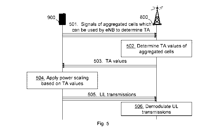
Figure 5 is a schematic combined flowchart and signalling scheme according to
some embodiments herein.
Action 501. The user equipment 900 transmits signals to the network node 800
over each respective aggregated cell which may be used by the network node 800
to
determine Timing Advance (TA) information.
Action 502. The network node 800 determines Timing Advance (TA) information
such as timing advance values based on analysis of the received signals for
each
respective aggregated cell.
Action 503. The network node 800 transmits the timing advance information,
e.g.
TA commands comprising timing advance values, to the user equipment 900.
Actions 504. The user equipment 900 applies power scaling in at least parts of
the
transition periods based on the received TA values or information.
Action 505. The user equipment 900 then performs UL transmissions using the
power scaling in the at least part of the transition periods.
Action 506. The network node 800 demodulates the UL transmissions taking into
account that power scaling has been applied in the at least parts of the
transition periods.
The network node 800 either knows the transition periods from the determined
Timing
advance information or by detecting the transmission zones during reception of
signals.
Within transition periods where one carrier, or cell, is still transmitting a
subframe n
but another subcarrier is already transmitting subframe n+1 UE transmit power
limitations
may arise. For example, even though the scheduling assignments may not lead to
any
transmit power limitation during the periods where all cells transmit the same
subframe,
transmit power may not be enough in transition periods if one cell increases
its requested
CA 02862197 2014-07-22
WO 2013/112089 PCT/SE2012/050629
transmit power but another cell is not yet transmitting the next subframe. See
Figure 3
above for an example. Today the transmit power is maintained, or a same power
level is
used, within a subframe since this helps during demodulation.
However, different embodiments will herein be described on how the available
5 transmit power may be shared across transmitting cells without there being a
problem that
transmit power is varied within a subframe. In some embodiments a specific
cell, e.g. a
Primary Cell (PCell) in CA, is protected, i.e. the user equipment 900 does not
apply any
power scaling whereas for other cells, such as Secondary Cells (SCell), the
user
equipment 900 has to reduce its transmit power in case of power limitations.
Other
10 embodiments propose to configure maximum powers per cell such that power
limitations
cannot happen.
Figure 6 is a block diagram depicting transmissions over time according to
some
embodiments herein. Power, actually transmit power, is defined along a
vertical axis and
time is defined along a horizontal axis. Power Uncertainty (PU) zones are
diagonally
striped. A Pcell, e.g. the first cell 41, has a Timing advance value defined
as TAP with
reference to TA=0. A SCe111, e.g. the second cell 42, has a Timing advance
value defined
as TA1 with reference to TA=0. A Sce112, e.g. the third cell 43, has a Timing
advance
value defined as TA2 with reference to TA=0. In this example all TA are
measured
towards the same timing reference TA=0, in a more general setup all TA may be
measured against different timing references. It is also illustrated that
different subframes
over the different cells are transmitted with different levels of transmit
power.
In the illustrated embodiments the transmitted power of the PCell within a
subframe
is not changed. The transmitted power of the PCell may of course change at
subframe
boundaries but is kept constant within a PCell. When stating that the transmit
power is
kept constant it is mostly meant here that the LTE standard does not actively
describe, or
support yet, a method to change the transmitted power from the user equipment
900.
Imperfections in the transceiver may nevertheless lead to power changes within
certain
tolerances. Thus no intentional change of transmit power is described in the
LTE
Standard this far, to the date of filing this disclosure.
All the required power reductions, if needed, are performed by SCells.
Depending
on the timing of SCells relative to the PCell the power scaling may occur at
the beginning,
end or beginning and end of a SCell subframe. In the example of Figure 6
SCe111 applies
the power scaling, if needed, at the end of a subframe, indicated by a PS1,
and SCe112 at
the beginning of a subframe, indicated by a PS2. It may also be possible that
SCe111
CA 02862197 2014-07-22
WO 2013/112089 PCT/SE2012/050629
11
starts to apply power scaling at the same time as SCe112, not shown in Figure
6. The
power scaling may vary within the power uncertainty period, which is denoted
as PU in
Figure 6.
The power scaling of SCells may be proprietary to the user equipment 900 or
can
be specified. In the simplest case the SCells set the transmitted power to
zero during their
power uncertainty periods, e.g. during the PU zones marked with dashed lines
between
subframe n and subframe n+1 and between subframe n+1 and subframe n+2 or
during
PS1/P52 zone. However, it should be appreciated that the power may be scaled
to any
other value. The power scaling may possibly be multiple different power
scaling over
different PU zones, and may be performed over a complete symbol comprising the
PU
zones or zones.
The reception performance of the PCell ¨ which may be argued is the most
important cell ¨ is never impaired. That is, the transmit power of the PCell
may not be
under power scaling. Also PUCCH orthogonality and SRS integrity of the PCell
are
maintained as no power scaling is performed. SRS transmission on SCells may be
impaired if the power scaling is applied at the end of the subframe. To avoid
SRS
impairments of SCells eNB may consider this during scheduling and make sure no
power
limitation will occur when a SCell SRS is sent since then probably also no
power scaling
needs to be applied.
The network node 800 is aware of the location of the PU zones and PS1/P52
zone,
due to the TA commands for each cell, for each cell and considers this during
demodulation of the received signal. For PUSCH, for example, soft values
within the PU
zones may be scaled differently. If the network node 800 does not know by how
much the
power is scaled a simple choice may be to set the soft value to zero, i.e.
ignore them
during decoding and demodulating.
If the user equipment 900 has no power limitation during uncertainty periods
or PU
zones it does not apply any power scaling due to multiple TA. If it switches
between no
scaling, i.e. no power limitation, and zero power, i.e. power limitation, the
network node
800 can make energy detection and determine if soft values during uncertainty
periods
should be ignored or used.
Instead of the PCell also another cell may be configured to be protected, i.e.
does
not apply scaling due to multiple TA. Such signaling may typically happen via
Radio
Resource Control (RRC) signaling. In figure 6 the PCell may be set to be the
first
Component Carrier or any other selected Component Carrier (CC).
CA 02862197 2014-07-22
WO 2013/112089 PCT/SE2012/050629
12
In some embodiments, depending on the timing of SCells relative to the PCell
the
power scaling of the Scells may occur at the beginning or end of an SCell
subframe. The
Pcell is protected and does not apply any scaling as it contains the important
PUCCH
information.
The user equipment 900 is assumed to know the target power, in the middle of
the
subframe, for each cell for the next subframe n+1. This may for instance be
obtained from
the information in the Downlink Control Information (DCI) and also the maximum
transmit
,or output, power for all cells combined is considered. The Scells adjusts
their power at
the beginning of subframe n+1 or end of subframe n dependent on the timing
relative to
the Pcell as follows.
An Scell that starts to transmit a subframe before the Pcell limits the power
used in
subframe n+1 to the power used in subframe n until subframe n has ended for
the Pcell
and then ramps its power to the target power for this Scell in subframe n+1.
It may also
set its power to zero during the transition period. This only applies if a
power limitation
occurs in the transition period.
An Scell that starts to transmit a subframe after the Pcell ramps the power
before
the end of subframe n to the target power of subframe n+1 for this Scell so
that when
subframe n+1 starts in the Pcell the Scell has reach its target power for
subframe n+1.
The Scell then keeps this power for the remaining time of subframe n and into
subframe
n+1. It may also set its power to zero during the transition period. This only
applies if a
power limitation is needed or occurs in the transition period.
Figure 7 is a block diagram depicting transmissions over time according to
some
embodiments herein. Figure 7 differs from figure 6 in that the power scaling
is performed
based on when transmitting subframes in time. Power, actually transmit power,
is defined
along a vertical axis and time is defined along a horizontal axis. PU zones
are diagonally
striped. CC1 has a Timing advance value defined as TA1 with reference to TA=0.
CC2
has a Timing advance value defined as TA2 with reference to TA=0. CC3 has a
Timing
advance value defined as TA3 with reference to TA=0. In this example all TA
are
measured towards the same timing reference TA=0, in a more general setup all
TA may
be measured against different timing references. It is also illustrated that
different
subframes over the different cells are transmitted with different levels of
transmit power.
In the illustrated embodiment the power scaling is applied at the beginning of
a
subframe. Power scaling, if needed, starts on a cell at the beginning of the
next subframe
on this cell and continues until the latest cell starts its next subframe. An
example is
CA 02862197 2014-07-22
WO 2013/112089 PCT/SE2012/050629
13
provided in Figure 7. An earliest cell 003, meaning that the cell 003
transmits a subframe
first in time, starts to reduce its transmit power, if needed, when it starts
to transmit the
new subframe. Cell CC1 ¨ which is next in time ¨ reduces its power, if needed,
starting
with its transition into the next subframe. If a reduction of CC1 is not
sufficient even CC3
may have to reduce its power further. In general power scaling may vary within
power
uncertainty periods, denoted in the figure as possibly multiple different
scaling. The latest
cell, i.e. CC2, does not apply any power scaling within the transition period
due to multiple
TA. The statement "does not apply any power scaling" means that the standard
does not
actively describe a method to change the transmitted power due to multiple TA
for this
cell, imperfections in the transceiver may nevertheless lead to power changes
within
certain tolerances.
The power scaling of cells may be proprietary to the user equipment 900 or may
be
specified. In the simplest case the cells set the transmitted power to zero
during their
power uncertainty periods.
PUCCH orthogonality is impaired unless the PCell is the latest cell; in this
case no
power scaling is applied. Since the power scaling is applied at the beginning
of a
subframe SRS transmissions are not impacted.
The network node 800 is aware of the location of the power uncertainty
periods,
due to the TA commands for each cell, for each cell and considers this during
demodulation of the received signal. For PUSCH, for example, soft values
within the PU
zones may be scaled differently. If the network node 800 does not know by how
much the
power is scaled a simple choice may be to set the soft value to zero, i.e.
ignore them
during decoding or demodulating.
If the user equipment 900 has no power limitation during uncertainty periods
it does
not apply any scaling due to multiple TA. If it switches between no scaling,
i.e. no power
limitation, and zero power, i.e. power limitation, the network node 800 may
make energy
detection and determine if soft values during uncertainty periods should be
ignored or
used.
Figure 8 is a block diagram depicting transmissions over time according to
some
embodiments herein. Figure 8 differs from figure 7 in that the power scaling
is performed
on cells transmitting after a cell, i.e. power scaling is not performed on a
cell transmitting a
subframe first in time. Power, actually transmit power, is defined along a
vertical axis and
time is defined along a horizontal axis. PU zones are diagonally striped. CC1
has a
Timing advance value defined as TA1 with reference to TA=0. CC2 has a Timing
advance
CA 02862197 2014-07-22
WO 2013/112089
PCT/SE2012/050629
14
value defined as TA2 with reference to TA=O. 003 has a Timing advance value
defined
as TA3 with reference to TA=O. In this example all TA are measured towards the
same
timing reference TA=O, in a more general setup all TA may be measured against
different
timing references. It is also illustrated that different subframes over the
different cells are
transmitted with different levels of transmit power.
Power scaling, if needed, is triggered when the earliest cell starts to
transmit the
new subframe. However, since power scaling is applied at the end of the
subframe it is
not the cell that changes into the next subframe that applies the power
scaling but all
other cells. In the example provided in Figure 8 third cell 003 is the
earliest. At the time
instance 003 starts with the next subframe power on 001 and/or 002 is reduced,
if
needed. At the time the next cell transitions into the next subframe, 001 in
the example,
cell 002 may have to reduce its transmit power even further since from now on
neither
001 nor 003 applies any scaling due to multiple TA. In general power scaling
may vary
within power uncertainty periods. The earliest cell never applies a power
scaling within the
transition period or PU zone due to multiple TA. SRS transmissions are
impaired since the
power scaling is applied at the end of a subframe. PUCCH orthogonality may
also be
impaired.
The statement "does not apply any power scaling" means that the standard does
not actively describe a method to change the transmitted power due to multiple
TA for this
cell, imperfections in the transceiver may nevertheless lead to power changes
within
certain tolerances.
The power scaling of cells may be proprietary to the user equipment 900 or may
be
specified. In the simplest case the cells set the transmitted power to zero
during their
power uncertainty periods.
The network node 800 is aware of the location of the power uncertainty
periods,
due to the TA commands for each cell, for each cell and considers this during
demodulation of the received signal. For PUSCH, for example, soft values
within the PU
zones may be scaled differently. If the network node 800 does not know by how
much the
power is scaled a simple choice may be to set the soft value to zero, i.e.
ignore them
during decoding or demodulating.
If the user equipment 900 has no power limitation during uncertainty periods
it does
not apply any scaling due to multiple TA. If it switches between no scaling,
i.e. no power
limitation, and zero power, i.e. power limitation, the network node 800 may
make energy
detection and determine if soft values during uncertainty periods should be
ignored or
used.
CA 02862197 2014-07-22
WO 2013/112089 PCT/SE2012/050629
Figure 9 is a block diagram depicting transmissions over time according to
some
embodiments herein. Figure 9 differs from figures 6-8 in that the power
scaling is
performed on all cells over the complete uncertainty periods. Power, actually
transmit
5 power, is defined along a vertical axis and time is defined along a
horizontal axis. PU
zones are diagonally striped. 001 has a Timing advance value defined as TA1
with
reference to TA=O. 002 has a Timing advance value defined as TA2 with
reference to
TA=O. 003 has a Timing advance value defined as TA3 with reference to TA=O. In
this
example all TA are measured towards the same timing reference TA=O, in a more
general
10 setup all TA may be measured against different timing references. It is
also illustrated that
different subframes over the different cells are transmitted with different
levels of transmit
power.
All cells may apply power scaling within the uncertainty period or PU zones if
the
requested transmit power exceeds the available transmit power, a maximum
transmit
15 power. As soon as the total requested power exceeds the available transmit
power,
transmit power is reduced on all currently transmitting cells, see Figure 9.
The transition
time, in this case the PU zone, during which power scaling may be needed
starts when
the earliest cell begins to transmit the next subframe and ends when the
latest cell starts
to transmit the new subframe. If the total requested power exceeds the
available transmit
power the transmit power of all currently transmitting cells is reduced.
The power scaling of cells may be proprietary to the user equipment 900 or may
be
specified. In the simplest case the cells set the transmitted power to zero
during their
power uncertainty periods.
Since the power scaling may happen both at the beginning and end of subframes
¨
depending on the timing of the cell with regards to other cells ¨ SRS and
PUCCH may be
impaired.
The network node 800 is aware of the location of the power uncertainty
periods, due
to the TA commands for each cell, for each cell and considers this during
demodulation of
the received signal. For PUSCH, for example, soft values within the PU zones
may be
scaled differently. If the network node 800 does not know by how much the
power is
scaled a simple choice may be to set the soft value to zero, i.e. ignore them
during
decoding or demodulating.
If the user equipment 900 has no power limitation during uncertainty periods
it does
not apply any scaling due to multiple TA. If it switches between no scaling,
i.e. no power
limitation, and zero power, i.e. power limitation, the network node 800 may
make energy
CA 02862197 2014-07-22
WO 2013/112089 PCT/SE2012/050629
16
detection and determine if soft values during uncertainty periods should be
ignored or
used.
Thus, according to the example embodiments, at least five different
embodiments
for applying power scaling may be considered. Some of them already discussed
earlier
and some are explained earlier but in different wordings.
Embodiment 1: Limit maximum power on each cell
A configured cap on the maximal power of each cell, e,g, cells 41,42,43, may
prevent power limitations within transition periods. The sum of these power
limits across
all cells should not exceed 23 dBm, minus some power back-offs specified in
RAN4. An
advantage of this method is that the transmit power within one subframe may be
constant
which improves reception in the network node 800. On the other hand maximum
bandwidth and Modulation and Coding Scheme (MCS) that may be allocated to a
cell is
limited, even though if there are no transmissions ongoing on other cells.
Embodiment 2: Scale the transmit power equally on all cells
As soon as the total requested power exceeds the available transmit power, the
power is reduced on all currently transmitting cells, such as all cells 41-43
also see Figure
9 above. The transition time, during which power scaling may be needed, starts
when the
earliest cell begins to transmit the next subframe and ends when the latest
cell starts to
transmit the new subframe.
Embodiment 2 is characterized in that the transition period/region/zone ¨ i.e.
the
time during which power uncertainties can occur ¨has the same (maximum) length
on
each cell. Depending on the relative timing this uncertainty may occur at the
end,
beginning, or both ends of a subframe. Due to power uncertainties within the
transition
periods reception performance degrades, especially since the transition
periods have
maximum length on all cells, which is the offset between latest and earliest
cell. Also
PUCCH orthogonality is impaired if e.g. parts of an SC-FDMA symbol are
transmitted with
less power.
Embodiment 3: Power scaling at beginning of subframe
Power scaling, if needed, starts on a cell, e.g. cells 41,42,43, at the
beginning of the
next subframe on this cell and continues until the latest cell starts its next
subframe. An
example is provided in Figure 7. The earliest cell CC3 starts to reduce its
transmit power,
CA 02862197 2014-07-22
WO 2013/112089 PCT/SE2012/050629
17
if needed, when 003 starts to transmit the new subframe. Cell CC1 ¨ which is
next in time
¨ reduces its transmit power, if needed, starting with its transition into the
next subframe.
If a reduction of CC1 is not sufficient even CC3 may have to reduce its power
further. The
latest cell CC2 does not apply any power scaling, on top of Release-10
scaling, within the
transition period.
Depending on the relative timing of a cell with regards to the other cells the
transition periods have different length but are never longer than in
Embodiment 2 above.
Since the network node 800 is aware of the relative timings, TA commands, the
network
node 800 knows the power uncertainty length of each cell and may use this
information to
improve reception performance compared to Embodiment 2. PUCCH orthogonality is
impaired unless the PCell is the latest cell, in this case no power scaling is
applied. Since
the power scaling is applied at the beginning of a subframe SRS transmissions
are not
impacted. Thus in this embodiment power scaling is applied at the beginning of
a new
subframe, if needed, and no power scaling is applied to the latest cell.
Embodiment 4: Power scaling at end of subframe
Power scaling, if needed, is triggered when the earliest cell starts to
transmit the
new subframe. However, since power scaling is applied at the end of the
subframe it is
not the cell that changes into the next subframe that applies the power
scaling but all
other cells. In the example provided in Figure 8 cell CC3 is earliest. At the
time instance
CC3 starts with the next subframe, the transmit power on CC1 and CC2 is
reduced, if
needed. At the time the next cell, CC1 in the example in Figure 8, transitions
into the next
subframe, cell CC2 may have to reduce its power even further since from now on
neither
CC1 nor CC3 applies any power scaling. The earliest cell never applies a power
scaling
within the transition period, on top of Release-10 scaling.
As in Embodiment 3 the power uncertainty period of a cell depends on its
relative
timing with regards to the other cells but is never longer than in Embodiment
2. Since the
network node 800 knows these relative timings the network node 800 may use
this
information to improve reception performance compared to Embodiment 2. SRS
transmissions are impaired since the power scaling is applied at the end of a
subframe.
PUCCH orthogonality is also impaired. Thus according to this embodiment power
scaling
is applied at the end of a subframe, if needed, no power scaling is applied to
the earliest
cell.
Embodiment 5: Power scaling is never applied to the PCell
CA 02862197 2014-07-22
WO 2013/112089 PCT/SE2012/050629
18
The PCell applies never power scaling within the power uncertainty period, on
top of
any Release-10 scaling. This has the advantage that PUCCH orthogonality is
maintained
and PCell PUSCH reception does not suffer from unequal powers within a
subframe. All
the required power reductions are performed by SCells. Depending on the timing
of
SCells relative to the PCell the power scaling may occur at the beginning or
end of an
SCell subframe. In the example of Figure 6 SCe111 applies the power scaling,
if needed, at
the end of a subframe and SCe112 at the beginning of a subframe.
The power uncertainty period of an SCell depends on its relative timing with
regards
to the other cells but is never longer than in Embodiment 2. Again, since the
network node
800 knows these relative timings the network node 800 may use this information
to
improve reception performance compared to Embodiment 2. Furthermore is
reception
performance of the PCell ¨ which may be argued is the most important cell ¨
never
impaired. Also PUCCH orthogonality and SRS integrity of the PCell are
maintained. SRS
transmission on SCells may be impaired if the power scaling is applied at the
end of the
subframe.
It should be appreciated that in the example embodiments described above,
cells in
which there is no power scaling applied by still experience slight variations
in power due
to imperfections in hardware.
Furthermore, a maximum power per UL cell maybe configured such that power
limitations in transition periods never occur. This configuration may
typically be signaled
with RRC signaling.
When comparing the different embodiments the following may be noted:
With Embodiment 1 no power, or almost no power, variations within a subframe
occur. However, even if power is not needed on other cells the transmit power
on any
given cell is limited to the configured limit. This may limit both performance
and coverage.
Embodiment 2 may lead to unequal transmit powers within a subframe on all
cells
and the power uncertainty periods have furthermore the maximum length on all
cells.
Compared to Embodiments 3 to 5 reception performance of Embodiment 2 is
inferior and
may in some cases not provide any benefits.
Embodiments 3 to 5 are rather similar with regards to power uncertainty
periods.
The PU zone has not maximum length on all cells and the network node 800 ¨
which
knows the timing uncertainty periods due to TA commands ¨ may use this
information to
improve reception performance. Embodiment 3 ¨ which applies power scaling at
the
CA 02862197 2014-07-22
WO 2013/112089 PCT/SE2012/050629
19
beginning of a subframe ¨ protects SRS transmissions. PUCCH orthogonality is
impaired
for both Embodiment 3 and 4. In Embodiment 5 ¨ power on the PCell is never
scaled ¨ no
PCell transmissions, such as SRS, PUCCH, and PUSCH, are impaired.
In this disclosure investigation is done on the problem of potential power
scaling of
cells as result of unaligned uplink transmissions due to multiple Timing
Advance values.
Following is two flowcharts Figures 10,11 illustrating implementation of some
of the
embodiments. The same procedures/flows may be when slightly modified
applicable for
other embodiments or embodiments.
Action 1001. The user equipment 900 starts to transmit subframe n+2 on Scell
2.
The user equipment 900 checks if it has reached the power maximum when
transmitting
subframe n+2 considering all cell it transmits.
Action 1002. If it has reached the power maximum, the user equipment 900
scales
the transmit power of SCell 2 in uncertainty period given by TA2 and TAP, so
that it does
not exceed the user equipment transmission/transmit power.
Action 1003. If it has not reached the power maximum, the user equipment 900
transmits the subframe n+2 with its given transmit power in uncertainty period
TA2 to
TAP.
Action 1004. If no further power scaling is applied the user equipment 900
will
transmit with the same transmit power on SCell 1 and SCell 2 for the remaining
part of the
subframe on each cell.
Figure 11 discloses some alternative embodiments of the method in user
equipment 900.
Action 1101. The user equipment 900 starts to transmit subframe n+2 on Pcell ¨
the User equipment 900 checks if it has reached the power maximum when
transmitting
subframe n+2 considering all cell it transmits.
Action 1102. If it has reached the power maximum, the user equipment 900
scales
the transmit power of SCell 1 and SCell 2 in uncertainty period given by TAP
and TA1, so
that it does not exceed the user equipment transmission/transmit power. The
user
equipment 900 transmits subframe n+2 on PCell with its given transmit power.
Action 1103. If it has not reached the power maximum, the user equipment 900
transmits the subframe n+2 on PCell with its given transmit power.
Action 1104. If no further power scaling is applied the user equipment 900
will
transmit with the same transmit power on SCell 2 and PCell for the remaining
part of the
CA 02862197 2014-07-22
WO 2013/112089 PCT/SE2012/050629
subframe on each cell. The power on SCell 1 will be set depending on
scheduling in
subframe n+2.
Note again that the flowcharts may be applicable to other embodiments than the
5 one disclosed by figure 6 and may therefore when slightly amended to
correspond to
other figures as well.
The example network may further include any additional elements suitable to
support communication between user equipments 900 or between the user
equipment
10 900 and another communication device, such as a landline telephone.
Although the
illustrated user equipment 900 may represent communication devices that
include any
suitable combination of hardware and/or software, these wireless devices may,
in
particular embodiments, represent devices such as the example user equipment
900
illustrated in greater detail by Figure 13. Similarly, although the
illustrated network nodes
15 may represent network nodes that include any suitable combination of
hardware and/or
software, these network nodes may, in particular embodiments, represent
devices such
as the example network node 800 illustrated in greater detail by Figure 15.
The method actions in the user equipment 900 for applying power scaling to
uplink
20 transmissions in a multiple cell communications network according to some
general
embodiments will now be described with reference to a flowchart depicted in
Figure 12.
The actions do not have to be taken in the order stated below, but may be
taken in any
suitable order. Actions performed in some embodiments are marked with dashed
boxes.
The user equipment 900 is configured to transmit over a plurality of
aggregated cells in
uplink to a network node 800.
Action 10. The user equipment 900 receives from the network node 800, timing
advance information for UL for one or more aggregated cells of the plurality
of aggregated
cells.
Action 11. The user equipment 900 may check whether uplink transmissions over
cells exceeds transmit power maximum of the user equipment 900 and in that
case apply
the power scaling.
Action 12. The user equipment 900 applies a power scaling to uplink
transmissions
of at least one aggregated cell out of the plurality of aggregated cells based
on the
received timing advance information. The at least one aggregated cell is
associated with
the user equipment 900 and is a cell of the multiple cell communications
network. In some
CA 02862197 2014-07-22
WO 2013/112089 PCT/SE2012/050629
21
embodiments the user equipment applies power scaling for a period of a
subframe of the
at least one aggregated cell, which period is based on the received timing
advance
information. A length in time of the period of the subframe may be based on
the received
timing advance information for one or more aggregated cells.
Action 14. The user equipment 900 may apply power scaling to uplink
transmissions of all aggregated cells, which are associated with the user
equipment 900.
In some embodiments the user equipment 900 applies the power scaling by
setting the
transmit power of at least one aggregated cell to zero. The power scaling may
be omitted
during uplink transmissions of sounding reference signals.
Action 16. The user equipment 900 may, in some embodiments, apply a maximum
power per UL cell such that power limitations in transition periods never
occur.
Action 18. The user equipment 900 may apply the power scaling by designating
at
least one aggregated cell of the multiple communications cell network as a
protected cell
and that power scaling is omitted on uplink transmissions of the protected
cell. The
protected cell may be a primary cell and/or at least one secondary cell. In
some
embodiments the protected cell is a cell that comprises a sub-frame that
occurs first in
time relative to subframes of other aggregated cells. In some embodiments the
protected
cell is a cell that comprises a sub-frame that occurs last in time relative to
subframes of
other aggregated cells.
Action 20. The user equipment 900 may apply the power scaling to a beginning,
an
end, or the beginning and the end of selected sub-frames of the at least one
aggregated
cell.
Action 22. The user equipment 900 may apply the power scaling to identified
regions of sub-frames with power limitations.
Action 24. The user equipment 900 may send to the network node 800 one or more
uplink transmissions with the applied power scaling.
Thus, some embodiments relate to a method, in a user equipment, for applying
power scaling in a multiple cell communications network in presence of
multiple uplink
timing advancements, each for uplink transmissions in respective cell in the
multiple cell
communications network. The method comprising: receiving (see action 10), from
a base
station, timing advancement information for the respective cell; and applying
(see action
12) a power scaling to uplink transmissions in at least one cell, associated
with the user
equipment, of the multiple cell communications network based on the received
timing
advancement information. The method of example embodiment 1, wherein the
applying
CA 02862197 2014-07-22
WO 2013/112089 PCT/SE2012/050629
22
the power scaling further comprises applying the power scaling to all
aggregated cells
which are associated with the user equipment. The method of example embodiment
2,
wherein the power scaling is applied equally to all aggregated cells. E.g.
during a
transition period, which transition period is based on the received timing
advance
information. The method of example embodiment 1, wherein applying the power
scaling
further comprises applying a maximum power per UL cell such that power
limitations in
transition periods never occur. The method of example embodiment 1, wherein
the
applying the power scaling further comprises designating at least one
aggregated cell of
the multiple communications cell network as a protected cell, such that no
power scaling
is applied to the protected cell. The applying the power scaling comprises to
apply power
scaling at a beginning of a subframe of a first cell until a beginning of a
second cell. The
applying the power scaling may comprise to apply power scaling at an end of a
subframe
of a first cell until an end of a second cell. The applying a power scaling
over the whole
subframe comprises reducing transmit power of at least one aggregated cell
over the
whole subframe taking transmit power of the different aggregated cells into
account
relative a maximum, also called Release-10 scaling. The method of example
embodiment
5, wherein the protected cell is a primary cell and/or at least one secondary
cell. The
method of any of examples embodiments 5 or 6, wherein the protected cell is a
cell which
comprises a sub-frame that occurs first in time. The method of any of example
embodiments 5-6, wherein the protected cell is a cell which comprises a sub-
frame that
occurs last in time. The method of any of example embodiments 1-8, wherein the
applying
the power scaling further comprises applying the power scaling to a beginning,
end,
and/or beginning and end of selected sub-frames of the at least one aggregated
cells. The
method of any of example embodiments 1-9, wherein the applying the power
scaling
further comprises applying the power scaling to identified regions of sub-
frames with
power limitations. The method of any of example embodiments 1-10, further
comprising
sending, to a base station, an uplink transmission.
Figure 13 is a block diagram depicting a user equipment according to some
embodiments herein for applying power scaling to uplink transmissions in a
multiple cell
communications network. The user equipment 900 is configured to transmit over
a
plurality of aggregated cells in uplink to a network node 800.
The user equipment 900 comprises a receiver 1301 configured to receive, from
the
network node 800, timing advance information for UL for one or more aggregated
cells of
the plurality of aggregated cells.
CA 02862197 2014-07-22
WO 2013/112089 PCT/SE2012/050629
23
The user equipment 900 further comprises an applying circuit 1302 configured
to
apply a power scaling to uplink transmissions of at least one aggregated cell
out of the
plurality of aggregated cells based on the received timing advance
information. The at
least one aggregated cell is associated with the user equipment 900 and is a
cell of the
multiple cell communications network.
In some embodiments, the applying circuit 1302 is configured to apply the
power
scaling for a period of a subframe of the at least one aggregated cell. The
period is based
on the received timing advance information. A length in time of the period of
the subframe
may be based on the received timing advance information for one or more
aggregated
cells.
In some embodiments, the applying circuit 1302 is configured to apply power
scaling to uplink transmissions of all aggregated cells. The aggregated cells
are
associated with the user equipment 900. The applying circuit 1302 may be
configured to
set the transmit power of at least one aggregated cell to zero. The applying
circuit 1302
may be configured to omit power scaling during uplink transmissions of
sounding
reference signals. The applying circuit 1302 may be configured to designate at
least one
aggregated cell of the multiple communications cell network as a protected
cell. The
applying circuit may further be configured to omit power scaling on uplink
transmissions of
the protected cell. The protected cell may be a primary cell and/or at least
one secondary
cell. The protected cell may be a cell that comprises a sub-frame that occurs
first in time
relative to subframes of other aggregated cells. In some embodiments, the
protected cell
may be a cell that comprises a sub-frame that occurs last in time relative to
subframes of
other aggregated cells.
The applying circuit 1302 may further be configured to apply the power scaling
to a
beginning, an end, or the beginning and the end of selected sub-frames of the
at least one
aggregated cell. The applying circuit 1302 may additionally be configured to
apply the
power scaling to identified regions of sub-frames with power limitations.
The user equipment 900 may also comprise a checking circuit 1303 configured to
check whether uplink transmissions over cells exceeds maximum transmit power
of the
user equipment 900. In that case, the applying circuit 1302 is configured to
perform the
power scaling.
T the user equipment 900 further comprises a transmitter 1304 that may be
configured to send to the network node 800 one or more uplink transmissions
with the
applied power scaling.
CA 02862197 2014-07-22
WO 2013/112089 PCT/SE2012/050629
24
The receiver 1301 and the transmitter 1304 may be comprised in a radio circuit
1305 in the user equipment 900. The applying circuit 1302 and/or the checking
circuit
1303 may be part of a processing circuit 1306.
As shown in Figure 13, the user equipment 900 or wireless device above
comprises
the processing circuitry 1306, a memory 1307, the radio circuitry 1305, and at
least one
antenna. The radio circuitry 1305 may comprise RF circuitry and baseband
processing
circuitry (not shown) which may be used to configure the user equipment 900
(UE)
according to one or more of the herein disclosed embodiments or embodiments.
In
particular embodiments, some or all of the functionality described above as
being
provided by mobile communication devices or other forms of wireless device may
be
provided by the processing circuitry 1306 executing instructions stored on a
computer-
readable medium, such as the memory 1307 shown in Figure 13. Alternative
embodiments of the user equipment 900 may include additional components beyond
those shown in Figure 13 that may be responsible for providing certain aspects
of the user
equipment's functionality, including any of the functionality described above
and/or any
functionality necessary to support the embodiment described above. The
circuitries
mentioned above may be used (any of them that is or in any combination) to
execute one
or more of the earlier mentioned embodiments, embodiment 1-5, and/or
embodiments 1-
5. The circuitries may also perform or include means for executing a
embodiment
according to the earlier disclosed flowcharts. All these circuitries may be
comprised in a
UE of an LTE system as earlier mentioned.
The various example embodiments described herein are described in the general
context of method steps or processes, which may be implemented in one aspect
by a
computer program product, embodied in a computer-readable medium, including
computer-executable instructions, such as program code, executed by computers
in
networked environments. A computer-readable medium may include removable and
non-
removable storage devices including, but not limited to, Read Only Memory
(ROM),
Random Access Memory (RAM), compact discs (CDs), digital versatile discs
(DVD), etc.
Generally, program modules may include routines, programs, objects,
components, data
structures, etc. that perform particular tasks or implement particular
abstract data types.
Computer-executable instructions, associated data structures, and program
modules
represent examples of program code for executing steps of the methods
disclosed herein.
The particular sequence of such executable instructions or associated data
structures
represents examples of corresponding acts for implementing the functions
described in
such steps or processes.
CA 02862197 2014-07-22
WO 2013/112089 PCT/SE2012/050629
Thus, embodiments herein relate to a user equipment for power scaling in a
presence of a multiple UL timing advancement in a multiple cell communications
network.
The user equipment comprises a radio circuitry 1305 configured to receive,
from a
5 network node 800, timing advancement information. The user equipment further
comprises a processing circuitry 1306 configured to apply a power scaling to
at least one
aggregated cell, associated with the user equipment, of the multiple cell
communications
network based on the received timing advancement information. The user
equipment of
example embodiment 15, wherein the processing circuitry 1306 is further
configured to
10 apply the power scaling to all aggregated cells which are associated with
the user
equipment. The user equipment of example embodiment 16, wherein the power
scaling is
applied equally to all aggregated cells. The user equipment of example
embodiment 15,
wherein the processing circuitry 1306 is further configured to apply a maximum
power per
UL cell such that power limitations in transition periods never occur. The
user equipment
15 of example embodiment 15, wherein the processing circuitry 1306 is further
configured to
designate at least one aggregated cell of the multiple communications cell
network as a
protected cell, such that no power scaling is applied to the protected cell.
The user
equipment of example embodiment 19, wherein the protected cell is a primary
cell and/or
at least one secondary cell. The user equipment of any of examples embodiments
19 or
20 20, wherein the protected cell is a cell which comprises a sub-frame that
occurs first in
time. The user equipment of any of example embodiments 19 or 20, wherein the
protected cell is a cell which comprises a sub-frame that occurs last in time.
The user
equipment of any of example embodiments 15-22, wherein the processing
circuitry 1306
is further configured to apply the power scaling to a beginning, end, and/or
beginning and
25 end of selected sub-frames of the at least one aggregated cells. The user
equipment of
any of example embodiments 15-23, wherein the processing circuitry 1306 is
further
configured to apply the power scaling to identified regions of sub-frames with
power
limitations. The user equipment of any of example embodiments 15-24, wherein
the radio
circuitry 1305 is further configured to send, to a base station, an uplink
transmission.
The method actions in the network node 800 for demodulating uplink
transmissions
from the user equipment 900 in a multiple cell communications network
according to
some general embodiments will now be described with reference to a flowchart
depicted
in Figure 14. The steps do not have to be taken in the order stated below, but
may be
CA 02862197 2014-07-22
WO 2013/112089 PCT/SE2012/050629
26
taken in any suitable order. The network node is configured to receive over a
plurality of
aggregated cells uplink transmissions from the user equipment 900.
Action 30. The network node 800 transmits, to the user equipment 900,
determined
timing advance information for UL of one or more aggregated cells of the
plurality of
aggregated cells.
Action 32. The network node 800 receives, from the user equipment 900, an
uplink
transmission of at least one aggregated cell out of the plurality of
aggregated cells.
Action 34. The network node 800 may weight soft values resulting in the
weighted
soft values for the periods. The network node 800 may set the soft values to
zero. E.g.
weight soft values in uncertainty periods in the received uplink transmission
based on the
transmitted timing advance information.
Action 36. The network node 800 may weight by identifying the periods in the
received uplink transmission. The network node 800 may identify the periods is
based on
determined timing advance information or detected uplink energy levels.
Identify periods
of increased power reduction, i.e. scaling, of the uplink transmission or
Identify periods of
less power reduction, i.e. scaling, in the received uplink transmission.
Action 38. The network node 800 may weight by identifying soft values of bits
associated with said periods of power scaling with a smaller or larger
weighting factors
during the demodulating of said received uplink transmission. E.g. provide
soft values of
bits associated with said periods a greater degree of trustworthiness,
weighting soft
values with larger numbers. The network node 800 may designate soft values of
bits
associated with said periods with a lower degree of trustworthiness, e.g.
weighting with
smaller numbers, during a decoding of the received uplink transmission.
Action 40. The network node 800 demodulates the received uplink transmission
using weighted soft values in periods in the received uplink transmission,
which periods
are based on the transmitted timing advance information.
CA 02862197 2014-07-22
WO 2013/112089
PCT/SE2012/050629
27
Thus, embodiments relate to a method, in a base station, for demodulating
uplink
transmissions in a presence of multiple UL timing advancement in a multiple
cell
communications network. The method comprising: transmitting, to a user
equipment,
timing advancement information; receiving, from a user equipment, an uplink
transmission; and weighting soft values in uncertainty periods in the received
uplink
transmission based on the transmitted timing advancement information. The
method of
example embodiment, wherein the weighting further comprises: identifying
portions or
periods of increased power reduction (scaling) in the received uplink
transmission; and
designating soft values of bits associated with said portions/periods with a
lower degree of
trustworthiness (weighting soft values with smaller numbers) during a decoding
of said
received uplink transmission. The method of any of example embodiments,
wherein the
weighting of soft values further comprises identifying portions/periods of
less power
reduction (scaling) in the received uplink transmission; and providing soft
values of bits
associated with said portions/periods of less power scaling a greater degree
of
trustworthiness, weighting soft values with larger numbers.
Figure 15 is a block diagram depicting a network node 800 according to some
embodiments herein for demodulating uplink transmissions from the user
equipment 900
in the multiple cell communications network. The network node 800 is
configured to
receive over a plurality of aggregated cells uplink transmissions from the
user equipment
900.
The network node 800 comprises a transmitter 1501 configured to transmit, to
the
user equipment 900, determined timing advance information for UL of one or
more
aggregated cells of the plurality of aggregated cells.
The network node 800 further comprises a receiver 1502 configured to receive,
from the user equipment 900, an uplink transmission of at least one aggregated
cell out of
the plurality of aggregated cells.
The network node 800 additionally comprises a demodulating circuit 1503
configured to demodulate the received uplink transmission using weighted soft
values in
periods in the received uplink transmission. The periods are based on the
transmitted
timing advance information.
The network node 800 may in some embodiments further comprise a weighting
circuit 1504 configured to weight soft values resulting in the weighted soft
values for the
periods. The weighting circuit 1504 may be configured to set the soft values
to zero. In
some embodiments the weighting circuit 1504 is configured to identify the
periods in the
CA 02862197 2014-07-22
WO 2013/112089 PCT/SE2012/050629
28
received uplink transmission. The weighting circuit 1504 is then further
configured to
provide soft values of bits associated with said periods of power scaling with
smaller or
larger weighting factors to the demodulating circuit 1503 of said received
uplink
transmission.
In some embodiments the weighting circuit 1504 is configured to identify the
periods
based on determined timing advance information or detected uplink energy
levels.
Thus, embodiments herein relate to the network node 800, e.g. a base station,
for
demodulating uplink transmissions in a presence of multiple UL timing
advancement in a
multiple cell communications network. The network node 800 may comprise a
radio
circuitry 1505 configured to send, to the user equipment 900, timing
advancement
information. The radio circuitry 1505 may further be configured to receive,
from the user
equipment 900, an uplink transmission. The network node 800 may further
comprise a
processing circuitry 1506 configured to weight soft values in uncertainty
periods in the
received uplink transmission based on the transmitted timing advancement
information. In
some embodiments the processing circuitry 1506 is further configured to
identify portions
of increased power reduction, scaling, in the received uplink transmission.
The processing
circuitry 1506 may further be configured to designate soft values of bits
associated with
said portions with a lower degree of trustworthiness (weighting soft values
with smaller
numbers) during a decoding of said received uplink transmission.
The processing circuitry 1506 may further be configured to identify portions
of less
power reduction or scaling in the received uplink transmission. The processing
circuitry
1506 may also be configured to provide soft values of bits associated with
said portions of
less power scaling a greater degree of trustworthiness, weighting soft values
with larger
numbers.
The network node 800 further comprises a memory 1507 that may comprise one or
more memory units and may be used to store for example data such as threshold
values,
quality values, user equipment context, timers, cyphering keys, application to
perform the
methods herein when being executed on the network node 800 or similar.
The description of the example embodiments provided herein have been presented
for purposes of illustration. The description is not intended to be exhaustive
or to limit
example embodiments to the precise form disclosed, and modifications and
variations are
possible in light of the above teachings or may be acquired from practice of
various
alternatives to the provided embodiments. The examples discussed herein were
chosen
and described in order to explain the principles and the nature of various
example
embodiments and its practical application to enable one skilled in the art to
utilize the
CA 02862197 2014-07-22
WO 2013/112089 PCT/SE2012/050629
29
example embodiments in various manners and with various modifications as are
suited to
the particular use contemplated. The features of the embodiments described
herein may
be combined in all possible combinations of methods, apparatus, modules,
systems, and
computer program products. It should be appreciated that the example
embodiments
presented herein may be practiced in any combination with each other.
It should be noted that the word "comprising" does not necessarily exclude the
presence of other elements or steps than those listed and the words "a" or
"an" preceding
an element do not exclude the presence of a plurality of such elements. It
should further
be noted that any reference signs do not limit the scope of the claims, that
the example
embodiments may be implemented at least in part by means of both hardware and
software, and that several "means", "units" or "devices" may be represented by
the same
item of hardware.