Note: Descriptions are shown in the official language in which they were submitted.
CA 02862317 2014-07-22
WO 2013/141952 PCT/US2013/021395
METHOD AND APPARATUS FOR ANTI-ICING AND DEICING POWER
TRANSMISSION LINES
BACKGROUND INFORMATION
FIELD
The present disclosure relates generally to anti-icing and
deicing transmission lines in a power transmission system.
Still more particularly, the present disclosure relates to a
method and apparatus for anti-icing and deicing transmission
lines without changing the amount of power that flows into the
power transmission system and the amount of power that flows out
of the power transmission system.
BACKGROUD
A power transmission system is configured to transfer
electrical energy generated by a power generation system to a
power distribution system. In some cases, a portion of the
transmission lines in a power transmission system are located
above ground and exposed to the air in the environment around
these transmission lines. Consequently, weather conditions in
the environment around these transmission lines may affect the
performance of these transmission lines.
For example, in some situations, weather conditions may
cause ice to form on these transmission lines. The different
types of weather conditions that may cause icing of transmission
lines may include, for example, without limitation, temperatures
below freezing, freezing rain, snow, sleet, and other types of
weather conditions.
Ice may form on a transmission line when a temperature of
the air around the transmission line is between about negative
1
CA 062317 201,1-072
WO 2013/141952 PCT/US2013/021395
three degrees Celsius (C ) and about two degrees Celsius (C ).
Other factors may also affect the formation of ice on a
transmission line. These other factors may include, for
example, the temperature of the transmission line, wind
velocity, humidity, and other suitable factors.
Currently, different solutions are available for anti-icing
and deicing transmission lines. Anti-icing includes preventing
ice from forming on transmission lines. Deicing includes
removing ice that has already formed on the transmission lines.
Some currently available methods for anti-icing and deicing
a transmission line include applying a short circuit alternating
current (AC) or a short circuit direct current (DC) to the
conductor in a transmission line to heat the transmission line.
However, these methods may cause an undesired interruption of
power flow through the power transmission system. Further,
these methods may require more electrical energy than desired to
heat the conductor to a desired temperature for anti-icing or
deicing.
Additionally, some currently available methods for anti-
icing and deicing a transmission line may require a human
operator to initiate one or more operations before anti-icing
and/or deicing can be performed. In some cases, a human
operator may be unable to initiate the operations needed for
anti-icing and/or de-icing to be performed as quickly as
desired.
Other currently available methods for anti-icing a
transmission line include applying a coating to the surface of
the transmission line. The coating is comprised of a material
configured to reduce the possibility of ice adhering to the
transmission line. However, the quality of the materials used
in the coating for these types of methods may decrease over
time. Consequently, a new coating may need to be reapplied to
reduce the possibility of ice adhering to the transmission line.
2
CA 062317 201,1-072
WO 2013/141952
PCT/US2013/021395
Further, this coating may not provide the ability to deice
a transmission line once ice has adhered to the transmission
line. Additionally, these materials used for the coating may be
more expensive than desired. Therefore, it would be desirable
to have a method and apparatus that takes into account one or
more of the issues discussed above as well as possibly other
issues.
SUMMARY
According to an aspect of the present disclosure there is
provided, a power transmission system comprises a plurality of
transmission lines and a control system. A first amount of
power flows into the power transmission system through the
plurality of transmission lines and a second amount of power
flows out of the power transmission system through the plurality
of transmission lines. The control system is configured to
change a flow of power through the plurality of transmission
lines such that icing of the plurality of transmission lines is
managed. The first amount of power flowing into the power
transmission system and the second amount of power flowing out
of the power transmission system remains substantially constant
after the flow of power through the plurality of transmission
lines is changed.
Advantageously the control system is configured to change
the flow of power through the plurality of transmission lines
such that a portion of the plurality of transmission lines is
anti-iced, wherein the first amount of power flowing into the
power transmission system and the second amount of power flowing
out of the power transmission system remains substantially
constant after the flow of power through the plurality of
transmission lines is changed.
Advantageously the control system is configured to change
the flow of power through the plurality of transmission lines
3
CA 062317 201,1-072
WO 2013/141952 PCT/US2013/021395
such that a portion of the plurality of transmission lines is
deiced, wherein the first amount of power flowing into the power
transmission system and the second amount of power flowing out
of the power transmission system remains substantially constant
after the flow of power through the plurality of transmission
lines is changed.
Advantageously the control system comprises: a plurality of
control devices distributed along the plurality of transmission
lines in which a control device in the plurality of control
devices located on a transmission line in the plurality of
transmission lines is configured to change a flow of electrical
current through the transmission line. Preferably the control
device is configured to change the flow of electrical current
through the transmission line by at least one of changing an
amount of electrical current that flows through the transmission
line, changing a voltage across the transmission line, and
changing an impedance for the transmission line. Alternatively,
the control device is selected from one of a distributed
flexible alternating current transmission system device, a
transformer, a switch, a controllable network transformer, and a
distributed series reactance device. Alternatively the control
system further comprises: a set of agents configured to control
the plurality of control devices based on sensor data received
from a monitoring system. Preferably the control system further
comprises: a main controller configured to send control data to
the set of agents, wherein the set of agents is configured to
control the plurality of control devices based on the sensor
data received from the monitoring system and the control data
received from the main controller.
Advantageously the power transmission system further
comprises: a monitoring system configured to monitor the
plurality of transmission lines and an environment around each
transmission line in the plurality of transmission lines.
Preferably the monitoring system comprises: a plurality of
4
CA 062317 201,1-072
WO 2013/141952
PCT/US2013/021395
sensor systems configured to generate sensor data about the
plurality of transmission lines and the environment around the
each transmission line in the plurality of transmission lines
and send the sensor data to the control system, wherein the
control system is configured to change the flow of power through
the plurality of transmission lines based on the sensor data.
Preferably each sensor system in the plurality of sensor
systems corresponds to a transmission line in the plurality of
transmission lines. Preferably a sensor system in the plurality
of sensor systems corresponding to a particular transmission
line in the plurality of transmission lines comprises a number
of sensors distributed in a number of locations along the
particular transmission line, wherein the number of sensors
includes at least one of a temperature sensor, a weather sensor,
a voltage sensor, a current sensor, a power sensor, a humidity
sensor, and an ice detection sensor. Preferably the first
amount of power flowing into the power transmission system and
the second amount of power flowing out of the power transmission
system remains substantially constant within selected tolerances
after the flow of power through the plurality of transmission
lines is changed.
According to an aspect of the present disclosure there is
provided, a method is provided for managing icing of a plurality
of transmission lines in a power transmission system. Sensor
data about the plurality of transmission lines and an
environment around each transmission line in the plurality of
transmission lines in the power transmission system is received.
A first amount of power flows into the power transmission system
through the plurality of transmission lines and a second amount
of power flows out of the power transmission system through the
plurality of transmission lines. A flow of power through the
plurality of transmission lines is changed based on the sensor
data such that the icing of the plurality of transmission lines
is managed. The first amount of power flowing into the power
5
CA 062317 201,1-072
WO 2013/141952
PCT/US2013/021395
transmission system and the second amount of power flowing out
of the power transmission system remains substantially constant
after the flow of power through the plurality of transmission
lines is changed.
Advantageously the step of changing the flow of power
through the plurality of transmission lines based on the sensor
data such that the icing of the plurality of transmission lines
is managed comprises: changing the flow of power through the
plurality of transmission lines such that a portion of the
plurality of transmission lines is anti-iced, wherein the first
amount of power flowing into the power transmission system and
the second amount of power flowing out of the power transmission
system remains substantially constant after the flow of power
through the plurality of transmission lines is changed.
Advantageously the step of changing the flow of power
through the plurality of transmission lines based on the sensor
data such that the icing of the plurality of transmission lines
is managed comprises: changing the flow of power through the
plurality of transmission lines such that a portion of the
plurality of transmission lines is deiced, wherein the first
amount of power flowing into the power transmission system and
the second amount of power flowing out of the power transmission
system remains substantially constant after the flow of power
through the plurality of transmission lines is changed.
Advantageously the step of changing the flow of power
through the plurality of transmission lines based on the sensor
data such that the icing of the plurality of transmission lines
is managed comprises: changing the flow of power through the
plurality of transmission lines based on the sensor data such
that the icing of the plurality of transmission lines is managed
using a plurality of control devices distributed along the
plurality of transmission lines, wherein a control device in the
plurality of control devices located on a transmission line in
the plurality of transmission lines is configured to change a
6
CA 02862317 2016-04-01
flow of electrical current through the transmission line.
Preferably the step of changing the flow of power through
the plurality of transmission lines based on the sensor
data such that the icing of the plurality of transmission
lines is managed using the plurality of control devices
distributed along the plurality of transmission lines,
wherein the control device in the plurality of control
devices located on the transmission line in the plurality
of transmission lines is configured to change the flow of
electrical current through the transmission line comprises
: changing the flow of electrical current through the
transmission line using the control device by at least one
of changing an amount of electrical current that flows
through the transmission line, changing a voltage across
the transmission line, and changing an impedance for the
transmission line.
Advantageously the step of changing the flow of power
through the plurality of transmission lines based on the
sensor data such that the icing of the plurality of
transmission lines is managed comprises: controlling a
plurality of control devices distributed along the
plurality of transmission lines to change the flow of power
through the plurality of transmission lines using a set of
agents, wherein the set of agents controls the plurality of
control devices based on the sensor data.
Advantageously the method further comprising:
generating the sensor data about the plurality of
transmission lines and the environment around the each
transmission line in the plurality of transmission lines
using a plurality of sensor systems.
7
CA 02862317 2016-04-01
According to an aspect of the present disclosure there
is provided a power transmission system comprising: a
plurality of transmission lines, wherein a first amount of
power flows into the power transmission system through the
plurality of transmission lines and a second amount of
power flows out of the power transmission system through
the plurality of transmission lines; and a control system
configured to change a flow of power through the plurality
of transmission lines such that icing of the plurality of
transmission lines is managed, wherein the first amount of
power flowing into the power transmission system and the
second amount of power flowing out of the power
transmission system remains substantially constant during
the change in the flow of power through the plurality of
transmission lines, and wherein the icing is managed by
increasing an amount of power flowing through a first
transmission line of the plurality of transmission lines
and decreasing an amount of power flowing through a second
transmission line of the plurality of transmission lines
while the first amount of power and the second amount of
power remain substantially constant.
According to an aspect of the present disclosure there
is provided a method for managing icing of a plurality of
transmission lines in a power transmission system, the
method comprising: receiving sensor data about the
plurality of transmission lines and an environment around
each transmission line in the plurality of transmission
lines in the power transmission system, wherein a first
amount of power flows into the power transmission system
through the plurality of transmission lines and a second
amount of power flows out of the power transmission system
through the plurality of transmission lines; and changing a
flow of power through the plurality of transmission lines
7a
CA 02862317 2016-04-01
based on the sensor data such that the icing of the
plurality of transmission lines is managed, wherein the
first amount of power flowing into the power transmission
system and the second amount of power flowing out of the
power transmission system remains substantially constant
during the change in the flow of power through the
plurality of transmission lines, and wherein the icing is
managed by increasing an amount of power flowing through a
first transmission line of the plurality of transmission
lines and decreasing an amount of power flowing through a
second transmission line of the plurality of transmission
lines while the first amount of power and the second amount
of power remain substantially constant.
The features and functions can be achieved
independently in various embodiments of the present
disclosure or may be combined in yet other embodiments in
which further details can be seen with reference to the
following description and drawings.
7b
CA 02862317 2014-07-22
WO 2013/141952 PCT/US2013/021395
BRIEF DESCRIPTION OF THE DRAWINGS
The novel features believed characteristic of the
illustrative embodiments are set forth in the appended claims.
The illustrative embodiments, however, as well as a preferred
mode of use, further objectives, and features thereof will best
be understood by reference to the following detailed description
of an illustrative embodiment of the present disclosure when
read in conjunction with the accompanying drawings, wherein:
Figure 1 is an illustration of a power transmission system
in the form of a block diagram in accordance with an
illustrative embodiment;
Figure 2 is an illustration of a power grid in accordance
with an illustrative embodiment;
Figure 3 is an illustration of a power grid in accordance
with an illustrative embodiment;
Figure 4 is an illustration of a process for managing icing
of a plurality of transmission lines in a transmission system in
the form of a flowchart in accordance with an illustrative
embodiment;
Figures 5A and 5B are illustrations of a process for
managing icing of a plurality of transmission lines in a
transmission system in the form of a flowchart in accordance
with an illustrative embodiment; and
Figure 6 is an illustration of a data processing system in
accordance with an illustrative embodiment.
8
CA 062317 201,1-072
WO 2013/141952
PCT/US2013/021395
DETAILED DESCRIPTION
The different illustrative embodiments recognize and take
into account different considerations. For example, the
different illustrative embodiments recognize and take into
account that some currently available methods for anti-icing and
deicing transmission lines may be unable to redistribute the
flow of power through a power transmission system to perform
these operations without increasing the power flow into and out
of the power transmission system more than desired.
Further, the different illustrative embodiments recognize
and take into account that it may be desirable to have a system
configured to perform anti-icing and deicing of transmission
lines without using more electrical energy than desired. The
different illustrative embodiments also recognize and take into
account that having a system configured to perform anti-icing
and deicing of transmission lines in response to substantially
real-time data may be desirable.
Thus, the different illustrative embodiments provide a
method and apparatus for managing icing of a plurality of
transmission lines in a power transmission system. In one
illustrative embodiment, a power transmission system comprises a
plurality of transmission lines and a control system. A first
amount of power flows into the power transmission system through
the plurality of transmission lines and a second amount of power
flows out of the power transmission system through the plurality
of transmission lines. The control system is configured to
change a flow of power through the plurality of transmission
lines such that icing of the plurality of transmission lines is
managed. The first amount of power flowing into the power
transmission system and the second amount of power flowing out
of the power transmission system remains substantially constant
after the flow of power through the plurality of transmission
lines is changed.
9
CA 02862317 2014-07-22
WO 2013/141952 PCT/US2013/021395
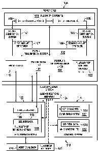
Referring now to the figures and, in particular, with
reference to Figure 1, an illustration of a power transmission
system in the form of a block diagram is depicted in accordance
with an illustrative embodiment. In these illustrative
examples, power transmission system 100, power generation system
101, and power distribution system 103 form power grid 104.
Power transmission system 100 is configured to transfer power
from power generation system 101 to power distribution system
103.
In these illustrative examples, first amount of power 107
flows into power transmission system 100 from power generation
system 101. Further, second amount of power 109 flows out of
power transmission system 100 into power distribution system
103.
As depicted, power transmission system 100 includes
plurality of transmission lines 102. As used herein, a
"plurality of" items means two or more items. For example,
plurality of transmission lines 102 means two or more
transmission lines.
As used herein, a "transmission line", such as one of
plurality of transmission lines 102, may comprise any number of
electrical lines electrically connected to each other and
configured to carry power. Further, an "electrical line", as
used herein, may comprise any number of conductors, insulators,
supporting structures, and/or other components used to carry
power from one location to another location. A "conductor", as
used herein, may be any material through which an electrical
current may flow. An "insulator", as used herein, may be any
material configured to resist the flow of an electrical current
through the material.
In these illustrative examples, when a first component is
electrically connected to a second component, the first
component is connected to the second component such that an
electrical current may flow from the first component to the
CA 062317 201,1-072
WO 2013/141952 PCT/US2013/021395
second component, the second component to the first component,
or a combination of the two. The first component may be
electrically connected to the second component without any
additional components between the two components. The first
component also may be electrically connected to the second
component by one or more other components.
In these illustrative examples, plurality of transmission
lines 102 is configured to electrically connect plurality of
points 105 in power grid 104 to each other. Plurality of points
105 in power grid 104 may include, for example, without
limitation, power generators, power generation stations,
substations, transformers, loads, buses, busbars, distribution
boards, and/or other electrical components.
As depicted, plurality of transmission lines 102 is
configured to transfer power between plurality of points 105 in
power grid 104. For example, plurality of transmission lines
102 may be configured to transfer power from set of starting
points 106 in power grid 104 to set of end points 108 in power
grid 104.
As used herein, a "set of" items means one or more items.
For example, set of starting points 106 may be one or more
starting points. In these illustrative examples, a starting
point in set of starting points 106 may be a point in power
transmission system 100 or a point in power generation system
101. For example, without limitation, a starting point in set
of starting points 106 may be a power source, a transmission
bus, a busbar, a substation, a power generation station, or some
other suitable type of component in power grid 104.
An end point in set of end points 108 may be a point in
power transmission system 100 or a point in power distribution
system 103. For example, without limitation, an end point in
set of end points 108 may be a substation, a load, a bus, a
busbar, or some other suitable type of component in power grid
104. In some illustrative examples, an end point for one
11
CA 062317 201,1-072
WO 2013/141952
PCT/US2013/021395
transmission line may be a starting point for another
transmission line.
Each transmission line in plurality of transmission lines
102 is configured to transfer power from a starting point in set
of starting points 106 to an end point in set of end points 108.
In these illustrative examples, more than one transmission line
in plurality of transmission lines 102 may carry power from a
same starting point in set of starting points 106. Further,
more than one transmission line in plurality of transmission
lines 102 may deliver power to a same end point in set of end
points 108.
In these illustrative examples, power transmission system
100 includes ice management system 110. Ice management system
110 is configured to manage icing of plurality of transmission
lines 102. Icing of a transmission line occurs when ice forms
on one or more of plurality of transmission lines 102. In these
illustrative examples, "ice" or "icing" may include frozen
water, frost, snow, or any combination of these three.
Ice management system 110 may be configured to prevent the
formation of ice on plurality of transmission lines 102. As
used herein, the process of preventing the icing of plurality of
transmission lines 102 may be referred to as "anti-icing".
Additionally, ice management system 110 may be configured
to remove ice that has already formed on plurality of
transmission lines 102. Removing ice that has formed on
plurality of transmission lines 102 may include removing some or
substantially all of the ice that has formed on plurality of
transmission lines 102. As used herein, the process of removing
ice that has formed on plurality of transmission lines 102 may
be referred to as "deicing".
In these illustrative examples, ice management system 110
includes monitoring system 112 and control system 114.
Monitoring system 112 is configured to monitor plurality of
transmission lines 102 and environment 115 around plurality of
12
CA 062317 201,1-072
WO 2013/141952
PCT/US2013/021395
transmission lines 102. In one illustrative example, monitoring
system 112 includes plurality of sensor systems 116 configured
to generate sensor data 118.
Each sensor system in plurality of sensor systems 116
corresponds to a transmission line in plurality of transmission
lines 102. Sensor system 120 is an example of one of plurality
of sensor systems 116. As depicted, sensor system 120
corresponds to transmission line 122 in plurality of
transmission lines 102.
Sensor system 120 may comprise one or more sensors
configured to monitor transmission line 122 and environment 115
around transmission line 122. These sensors may include, for
example, without limitation, a temperature sensor, a weather
sensor, a voltage sensor, a current sensor, a power sensor, a
humidity sensor, an ice detection sensor, and/or other suitable
types of sensors. In this manner, sensor data 118 generated by
plurality of sensor systems 116 may include sensor data about
plurality of transmission lines 102 and sensor data about
environment 115 around each of plurality of transmission lines
102.
A sensor in sensor system 120 may correspond to
transmission line 122 in a number of different ways. For
example, the sensor may be physically attached to transmission
line 122, electrically connected to transmission line 122,
attached to a structure near transmission line 122, or
associated with transmission line 122 in some other suitable
manner.
Sensor data 118 generated by plurality of sensor systems
116 is sent to control system 114 using communications network
124 in ice management system 110. Communications network 124
may include any number of wireless communications links, wired
communications links, optical communications links, and/or other
suitable types of communications links. In some cases,
plurality of sensor systems 116 may send sensor data 118 to
13
CA 062317 201,1-072
WO 2013/141952
PCT/US2013/021395
control system 114 over one or more of plurality of transmission
lines 102.
In these illustrative examples, control system 114
comprises set of agents 126 and plurality of control devices
128. As used herein, an "agent" in set of agents 126 may be any
type of controller configured to communicate with and/or control
at least one sensor system in plurality of sensor systems 116
and at least one control device in plurality of control devices
128. An agent in set of agents 126 may be implemented using
hardware, software, or a combination of both.
For example, set of agents 126 may be implemented in
computer system 130. Computer system 130 may comprise a number
of computers. When more than one computer is present in
computer system 130, these computers are in communication with
each other. Further, these computers may be located in a same
location or in different locations, depending on the
implementation.
Set of agents 126 receives and processes sensor data 118.
Set of agents 126 uses sensor data 118 to control plurality of
control devices 128. For example, set of agents 126 may send
commands to plurality of control devices 128 using
communications network 124.
Plurality of control devices 128 may be distributed along
plurality of transmission lines 102. One or more of plurality
of control devices 128 may be located on a same transmission
line in plurality of transmission lines 102. A control device
in plurality of control devices 128 may be associated with a
transmission line in plurality of transmission lines 102 by
being electrically connected to the transmission line,
magnetically coupled to the transmission line, or associated
with the transmission line in some other suitable manner.
In these illustrative examples, a control device in
plurality of control devices 128 is any device configured to
change a flow of electrical current through the transmission
14
CA 062317 201,1-072
WO 2013/141952
PCT/US2013/021395
line on which the control device is located. The control device
may change the flow of electrical current through the
transmission line in a number of different ways. For example,
without limitation, the control device may change the flow of
electrical current through the transmission line by changing an
amount of electrical current that flows through the transmission
line, changing a voltage across the transmission line, changing
an impedance for the transmission line, and/or changing the flow
power through the transmission line in some other suitable
manner.
A control device in plurality of control devices 128 may be
selected from one of, for example, without limitation, a
distributed flexible alternating current transmission system
device, a transformer, a controllable network transformer (CNT),
a distributed series reactance (DSR) device, a switch, or some
other suitable type of control device. In one illustrative
example, plurality of control devices 128 may form a distributed
flexible alternating current transmission system (DFACTS). In
this illustrative example, each control device in plurality of
control devices 128 may be a distributed flexible alternating
current transmission system (DFACTS) device.
Set of agents 126 uses sensor data 118 to determine whether
the possibility of ice forming on any transmission line in
plurality of transmission lines 102, such as, for example,
transmission line 122, is greater than selected tolerances. If
the possibility of ice forming on a particular transmission line
is greater than selected tolerances, set of agents 126 controls
the portion of plurality of control devices 128 located on that
transmission line to increase the flow of electrical current
through that transmission line.
Increasing the flow of electrical current through this
transmission line heats the transmission line to reduce the
possibility of ice forming on the transmission line. In
particular, set of agents 126 controls the portion of plurality
CA 062317 201,1-072
WO 2013/141952
PCT/US2013/021395
of control devices 128 located on the particular transmission
line to heat the transmission line such that water does not
adhere to the transmission line and solidify to form frost or
ice. In other words, set of agents 126 performs anti-icing of
the transmission line based on sensor data 118 using the portion
of plurality of control devices 128 located on the particular
transmission line.
Further, set of agents 126 may also use sensor data 118 to
determine whether ice has already formed on any transmission
line in plurality of transmission lines 102. If ice has formed
on a particular transmission line, set of agents 126 controls
the portion of plurality of control devices 128 located on that
transmission line to increase the flow of electrical current
through that transmission line. The flow of electrical current
is increased such that the transmission line is heated to a
temperature that causes the ice on the transmission line to
melt. In this manner, set of agents 126 performs deicing of the
transmission line using one or more of plurality of control
devices 128.
In these illustrative examples, set of agents 126 performs
anti-icing and deicing in a manner such that first amount of
power 107 that flows into power transmission system 100 and
second amount of power 109 that flows out of power transmission
system 100 remains substantially constant. In particular, anti-
icing and deicing are performed such that first amount of power
107 and second amount of power 109 remain substantially constant
within selected tolerances.
More than one transmission line may carry power away from
power generation system 101 and/or deliver power to power
distribution system 103. Set of agents 126 is configured to use
plurality of control devices 128 to redistribute the flow of
power through plurality of transmission lines 102 in power
transmission system 100 such that first amount of power 107
flowing into power transmission system 100 and second amount of
16
CA 062317 201,1-072
WO 2013/141952
PCT/US2013/021395
power 109 flowing out of power transmission system 100 remains
substantially constant.
When the flow of power through plurality of transmission
lines 102 is redistributed to perform anti-icing and/or deicing
operations, the net flow of power through a particular starting
point in set of starting points 106 or a particular end point in
set of end points 108 remains substantially zero within selected
tolerances. However, the amount of power flowing into or out of
a point in plurality of points 105 through a particular
transmission line may be increased or decreased.
In this manner, set of agents 126 may perform anti-icing
and/or deicing of one or more of plurality of transmission lines
102 without changing the overall flow of power into and out of
power transmission system 100 outside of selected tolerances.
Of course, the amount of power flowing into and/or out of power
transmission system 100 may be changed independently of the
anti-icing and deicing processes. Further, set of agents 126
may use sensor data 118 to control plurality of control devices
128 such that anti-icing and deicing is initiated in
substantially real-time. In other words, unintentional delays
in the time needed to initiate anti-icing and deicing based on
sensor data 118 may be reduced.
In these illustrative examples, the agents in set of agents
126 may work cooperatively and/or independently of each other.
In one illustrative example, each agent in set of agents 126 may
be configured to receive a particular portion of sensor data 118
from a particular portion of plurality of sensor systems 116.
Further, each agent may be configured to control the portion of
plurality of control devices 128 located on a particular portion
of plurality of transmission lines 102.
In some illustrative examples, set of agents 126 may be
controlled by main controller 132 in control system 114. Main
controller 132 may be implemented in computer system 130 or some
other computer system, depending on the implementation. In some
17
CA 062317 201,1-072
WO 2013/141952 PCT/US2013/021395
cases, main controller 132 is part of a power operations center
for power grid 104.
Set of agents 126 may control plurality of control devices
128 based on control data 134 received from main controller 132
in addition to or in place of sensor data 118, depending on the
implementation. Main controller 132 may send control data 134
to set of agents 126 using communications network 124. Control
data 134 may comprise any number of policies, commands, rules,
regulations, requirements, customer requests, safety alerts,
and/or other suitable types of data.
In some illustrative examples, set of agents 126 may
require authorization from main controller 132 to change the
flow of power through plurality of transmission lines 102 using
plurality of control devices 128 to perform deicing operations.
However, in these examples, set of agents 126 may not require
authorization to change the flow of power through plurality of
transmission lines 102 to perform anti-icing operations.
In other illustrative examples, set of agents 126 may
determine that the amount of power flowing through plurality of
transmission lines 102 is insufficient to perform anti-icing
and/or deicing operations based on sensor data 118 and control
data 134. For example, set of agents 126 may be unable to
redistribute the flow of power through plurality of transmission
lines 102 using plurality of control devices 128 in a manner
that heats a transmission line to the temperature needed to
deice or anti-ice the transmission line.
In these situations, set of agents 126 may send a request
to main controller 132 or some other suitable operations center
requesting that first amount of power 107 flowing into power
transmission system 100 from power generation system 101 and
second amount of power 109 flowing out of power transmission
system 100 be increased. In other words, power generation by
power generation system 101 and load consumption by power
distribution system 103 may be increased.
18
CA 062317 201,1-072
WO 2013/141952
PCT/US2013/021395
In some illustrative examples, set of agents 126 may use
additional data 138 provided by number of sources 140 to manage
icing of plurality of transmission lines 102. Additional data
138 may include, for example, without limitation, weather
forecasts, icing reports, wind data, police reports, observation
reports, and/or other suitable data that may be used to
determine when the flow of power through plurality of
transmission lines 102 needs to be redistributed to remove
and/or prevent icing on one or more of plurality of transmission
lines 102.
Number of sources 140 may include, for example, without
limitation, a weather station, a police station, human
operators, and/or other suitable sources of additional data 138.
As depicted, number of sources 140 may be separate from ice
management system 110. However, in some cases, one or more of
number of sources 140 may be considered part of monitoring
system 112.
The illustration of power transmission system 100 in Figure
1 is not meant to imply physical or architectural limitations to
the manner in which an illustrative embodiment may be
implemented. Other components in addition to or in place of the
ones illustrated may be used. Some components may be optional.
Also, the blocks are presented to illustrate some functional
components. One or more of these blocks may be combined,
divided, or combined and divided into different blocks when
implemented in an illustrative embodiment.
For example, in some cases, one or more of set of agents
126 may be implemented in one or more of plurality of control
devices 128. Further, in some illustrative examples, when more
than one agent is present in set of agents 126, these agents may
be implemented in computers located remotely to each other. In
other illustrative examples, set of agents 126 may be
implemented as part of main controller 132.
19
CA 062317 201,1-072
WO 2013/141952 PCT/US2013/021395
With reference now to Figure 2, an illustration of a power
grid is depicted in accordance with an illustrative embodiment.
Power grid 200 is an example of one implementation for power
grid 104 in Figure 1. As depicted, power transmission system
202 is part of power grid 200. Power transmission system 202 is
an example of one implementation for power transmission system
100 in Figure 1.
Power transmission system 202 includes plurality of
transmission lines 204. Plurality of transmission lines 204 is
configured to transfer power between different points in power
grid 200. As depicted, transmission lines 206, 208, 210, 212,
214, 216, and 218 are examples of transmission lines in
plurality of transmission lines 204.
Transmission line 206 carries power between bus 220 and bus
222. Transmission line 208 carries power between bus 220 and
bus 224, and transmission line 210 carries power between bus 222
and bus 224. Further, transmission line 212 carries power
between bus 222 and bus 226. Transmission line 214 carries
power between bus 222 and bus 228, and transmission line 216
carries power between bus 224 and bus 228. Transmission line
218 carries power between bus 226 and bus 228.
Bus 220 receives power from generator 221. Bus 222
receives power from generator 223 and sends power to load 225.
Bus 224 sends power to load 227.
As depicted, the flow of electrical current through
transmission line 206 in the direction of arrow 230 is about
1,472 amperes (A). The flow of electrical current through
transmission line 208 in the direction of arrow 232 is about 702
amperes (A). In this manner, the total amount of electrical
current flowing from bus 220 may be about 2,174 amperes (A).
Further, the flow of electrical current through
transmission line 210 in the direction of arrow 234 is about 397
amperes (A). The total flow of electrical current into bus 222
CA 062317 201,1-072
WO 2013/141952
PCT/US2013/021395
with respect to transmission line 206 and transmission line 210
is about 1,075 amperes (A).
In this illustrative example, power transmission system 202
includes ice management system 240. Ice management system 240
is configured to manage icing of plurality of transmission lines
204. Ice management system 240 includes monitoring system 242
and control system 244.
Monitoring system 242 includes a plurality of sensor
systems corresponding to plurality of transmission lines 204.
Sensor systems 246, 248, 250, 252, 254, 256, and 258 are
examples of sensor systems in monitoring system 242. Sensor
systems 246, 248, 250, 252, 254, 256, and 258 correspond to
transmission lines 206, 208, 210, 212, 214, 216, and 218,
respectively. Each of these sensors systems comprises one or
more sensors configured to monitor the corresponding
transmission line and the environment around the corresponding
transmission line.
Control system 244 includes a set of agents and a plurality
of control devices distributed along plurality of transmission
lines 204. Agent 245 is an example of one of the set of agents
in control system 244. Agent 245 is configured to receive
sensor data from monitoring system 242. In particular, agent
245 is configured to receive sensor data from the different
sensor systems in monitoring system 242.
Control devices 260, 262, 264, 266, 268, 270, 272, 274,
276, 278, 280, 282, 284, and 286 are examples of control devices
in control system 244. As depicted, control device 260 and
control device 262 are located on transmission line 206.
Control device 264 and control device 266 are located on
transmission line 208. Control device 268 and control device
270 are located on transmission line 210.
Further, control device 272 and control device 274 are
located on transmission line 212. Control device 276 and
control device 278 are located on transmission line 214.
21
CA 062317 201,1-072
WO 2013/141952
PCT/US2013/021395
Control device 280 and control device 282 are located on
transmission line 216, and control device 284 and control device
286 are located on transmission line 218.
Agent 245 uses the sensor data received from monitoring
system 242 to determine whether anti-icing and/or deicing of one
or more of plurality of transmission lines 204 is needed. Agent
245 may control any number of the control devices in control
system 244 to perform anti-icing and/or deicing of one or more
of plurality of transmission lines 204.
With reference now to Figure 3, an illustration of a power
grid is depicted in accordance with an illustrative embodiment.
In this illustrative example, agent 245 makes a determination
that the possibility of ice forming on transmission line 208 is
greater than selected tolerances. This determination may be
based on weather data for the environment around transmission
line 208 and a temperature for transmission line 208 received in
sensor data from sensor system 248.
Based on this determination, agent 245 controls control
device 264 and control device 266 to change the flow of power
through transmission line 208 to perform anti-icing of
transmission line 208. In particular, the flow of electrical
current through transmission line 208 is increased in the
direction of arrow 232.
This increase in the flow of electrical current through
transmission line 208 heats transmission line 208 to a
temperature that reduces the possibility of water adhering to
transmission line 208 and solidifying as frost or ice. The flow
of electrical current through transmission line 208 in the
direction of arrow 232 is increased to about 951 amperes (A).
This increase in the flow of electrical current through
transmission line 208 may increase the amount of power carried
from bus 220 and may increase the amount of power delivered to
bus 224 more than desired. Agent 245 is configured to control
the flow of power through plurality of transmission lines 204
22
CA 062317 201,1-072
WO 2013/141952
PCT/US2013/021395
such that the overall flow of power to and from bus 220, bus
222, and bus 224 remains substantially constant within selected
tolerances. In this illustrative example, the selected
tolerances may be, for example, without limitation, about 10
amperes (A).
For example, agent 245 decreases the flow of electrical
current through transmission line 206 in the direction of arrow
230 to about 1,223 amperes (A). Agent 245 performs this
decrease in the flow of electrical current through transmission
line 206 using control device 260 and control device 262.
The total amount of electrical current flowing from bus 220
is about 2,174 amperes (A). This amount of electrical current
is substantially equal to the amount of electrical current that
flowed from bus 220 prior to anti-icing of transmission line
208.
Further, agent 245 decreases the flow of electrical current
through transmission line 210 in the direction of arrow 234 to
about 176 amperes (A). Agent 245 performs this decrease in the
flow of electrical current through transmission line 210 using
control device 268 and control device 270.
The total flow of electrical current into bus 222 with
respect to transmission line 206 and transmission line 210 is
about 1,047 amperes (A). The difference between this total flow
of electrical current into bus 222 and the total flow of
electrical current into bus 222 prior to anti-icing with respect
to transmission line 206 and transmission line 210 is less than
about 10 amperes (A).
In this manner, agent 245 performs anti-icing for
transmission line 208 without changing the overall flow of power
between bus 220, bus 222, and bus 224 more than selected
tolerances. In particular, agent 245 performs anti-icing for
transmission line 208 without changing the total amount of power
flowing into power transmission system 202 and without changing
23
CA 062317 201,1-072
WO 2013/141952 PCT/US2013/021395
the total amount of power flowing out of power transmission
system 202.
For example, anti-icing is performed without changing the
power generated by generator 221 that flows into bus 220 or the
power generated by generator 223 that flows into bus 222.
Further, anti-icing is performed without changing the power sent
to load 225 from bus 222 or the power sent to load 227 from bus
224. Although this illustrative example has been described with
respect to anti-icing, agent 245 may perform deicing of
transmission line 208 in a similar manner.
The illustrations of power grid 200 in Figure 2 and Figure
3 are not meant to imply physical or architectural limitations
to the manner in which an illustrative embodiment may be
implemented. Other components in addition to or in place of the
ones illustrated may be used. Some components may be optional.
The different components shown in Figure 2 and Figure 3 may
be combined with components in Figure 1, used with components in
Figure 1, or a combination of the two. Additionally, some of
the components in these figures may be illustrative examples of
how components shown in block form in Figure 1 may be
implemented as physical structures.
With reference now to Figure 4, an illustration of a
process for managing icing of a plurality of transmission lines
in a transmission system is depicted in accordance with an
illustrative embodiment. The process illustrated in Figure 4
may be implemented using, for example, ice management system 110
in Figure 1, and to manage the formation of ice on, for example,
plurality of transmission lines 102 in power transmission system
100 in Figure 1.
The process begins by receiving sensor data about a
plurality of transmission lines and an environment around each
transmission line in the plurality of transmission lines in the
power transmission system (operation 400). In operation 400,
the sensor data may include, for example, temperature data for
24
CA 062317 201,1-072
WO 2013/141952
PCT/US2013/021395
the plurality of transmission lines, weather data, humidity
data, environmental temperature data, and/or other suitable
data. The sensor data may be received from a plurality of
sensor systems corresponding to the plurality of transmission
lines.
The plurality of transmission lines is configured to
electrically connect a plurality of points in a power grid to
each other. A first amount of power flows into the power
transmission system from a power generation system. A second
amount of power flows out of the power transmission system into
a power distribution system.
The process then determines whether ice has formed on any
transmission lines in the plurality of transmission lines
(operation 402). Ice on a transmission line may include frozen
water, frost, snow, or a combination of these three.
If the process determines that ice has formed on one or
more transmission lines in the plurality of transmission lines,
the process changes the flow of power through the plurality of
transmission lines to deice these iced transmission lines
without changing the first amount of power flowing into the
power transmission system or the second amount of power flowing
out of the power transmission system (operation 404). In other
words, the first amount of power flowing into the power
transmission system and the second amount of power flowing out
of the power transmission system remains substantially constant
within selected tolerances after the flow of power through the
plurality of transmission lines is changed.
The process then determines whether a possibility of ice
forming on any transmission line in the plurality of
transmission lines is greater than selected tolerances
(operation 406). If the process determines that the possibility
of ice forming on one or more transmission line in the plurality
of transmission lines is not greater than selected tolerances,
the process returns to operation 400 as described above.
CA 062317 201,1-072
WO 2013/141952
PCT/US2013/021395
Otherwise, the process changes the flow of power through
the plurality of transmission lines to anti-ice the transmission
lines without changing the first amount of power flowing into
the power transmission system or the second amount of power
flowing out of the power transmission system (operation 408).
The process then returns to operation 400 as described above.
With reference again to operation 402, if the process
determines that ice has not formed on any transmission line in
the plurality of transmission lines, the process proceeds to
operation 406 as described above. In this manner, the process
described in Figure 4 may change the flow of power through the
plurality of transmission lines to manage icing of the plurality
of transmission lines without changing the power generated by
the power generation system and the power received by the power
distribution system.
With reference now to Figures 5A and 5B, illustrations of a
process for managing icing of a plurality of transmission lines
in a transmission system is depicted in accordance with an
illustrative embodiment. The process illustrated in Figures 5A
and 5B may be implemented using ice management system 110 to
manage the formation of ice on plurality of transmission lines
102 in power transmission system 100 in Figure 1. In
particular, this process may be implemented using set of agents
126 in ice management system 110 in Figure 1.
The process begins by receiving sensor data for a plurality
of transmission lines in a power transmission system (operation
500). The sensor data may include sensor data about the
plurality of transmission lines and sensor data about an
environment around each of the plurality of transmission lines.
For example, the sensor data may include, without limitation,
environmental temperature data, wind speed data, humidity data,
weather data, ice detection measurements, transmission line
temperature data, and/or other suitable types of data. In this
illustrative example, the sensor data may be continuously or
26
CA 062317 201,1-072
WO 2013/141952
PCT/US2013/021395
periodically received by the set of agents during the process
described in Figure 5.
The process then selects a transmission line in the
plurality of transmission lines (operation 501). Next, the
process identifies the sensor data corresponding to the selected
transmission line (operation 502).
Thereafter, the process determines whether the selected
transmission line has a deicing status (operation 504). A
transmission line has a deicing status when the transmission
line is currently being deiced. If the selected transmission
line does not have the deicing status, the process determines
whether a thickness of ice on the selected transmission line is
greater than a maximum threshold (operation 506). When ice is
not present on the selected transmission line, the thickness of
the ice may be substantially zero.
If the thickness of ice on the selected transmission line
is not greater than the maximum threshold, the process
determines whether a temperature of the environment around the
selected transmission line is within a selected range of
temperatures (operation 508). The selected range of
temperatures may be, for example, between about negative four
degrees Celsius (C ) and about two degrees Celsius (C ).
If the temperature of the environment around the selected
transmission line is within the selected range of temperatures,
the process calculates the amount of electrical current needed
to substantially prevent the formation of ice on the selected
transmission line (operation 510). The process then determines
whether the current amount of electrical current flowing through
the selected transmission line is substantially equal to or
greater than the calculated amount of electrical current
(operation 512).
If the current amount of electrical current flowing through
the selected transmission line is not substantially equal to or
greater than the calculated amount of electrical current, the
27
CA 062317 201,1-072
WO 2013/141952
PCT/US2013/021395
process calculates the possibility of ice forming on the
selected transmission line based on other sensor data (operation
514). The process then determines whether the selected
transmission line needs to be anti-iced (operation 516). In
operation 516, this determination may be made based on whether
the possibility of ice forming on the selected transmission line
is greater than selected tolerances.
If the selected transmission line needs to be anti-iced,
the process sets the status of the selected transmission line to
an anti-icing status (operation 518). Thereafter, the process
determines whether any additional unprocessed transmission lines
are present in the plurality of transmission lines (operation
520). If any unprocessed transmission lines are present, the
process returns to operation 501 as described above.
Otherwise, the process changes the flow of power through
the plurality of transmission lines to perform deicing of the
transmission lines having a deicing status and to perform anti-
icing of the transmission lines having an anti-icing status
(operation 522). The process then returns to operation 500 as
described above.
With reference again to operation 516, if the selected
transmission line does not need to be anti-iced, the process
sets the status of the selected transmission line to a normal
status (operation 524). The process then returns to operation
520 as described above.
With reference again to operation 512, if the amount of
electrical current flowing through the selected transmission
line is substantially equal to or greater than the calculated
amount of electrical current, the process proceeds to operation
524 as described above. With reference again to operation 508,
if the temperature of the environment around the selected
transmission line is not within the selected range of
temperatures, the process proceeds to operation 524 as described
above.
28
CA 062317 201,1-072
WO 2013/141952
PCT/US2013/021395
Further, with reference again to operation 506, if the
thickness of ice on the selected transmission line is greater
than the maximum threshold for ice thickness, the process sets
the status of the selected transmission line to a deicing status
(operation 526). The process then proceeds to operation 520 as
described above.
With reference again to operation 504, if the selected
transmission line has a deicing status, the process determines
whether a thickness of ice on the selected transmission line is
less than or substantially equal to a minimum threshold
(operation 528). If the thickness of ice on the selected
transmission line is not less than or substantially equal to the
minimum threshold, the process proceeds to operation 520 as
described above. Otherwise, the process proceeds to operation
524 as described above.
The flowcharts and block diagrams in the different depicted
embodiments illustrate the architecture, functionality, and
operation of some possible implementations of apparatuses and
methods in an illustrative embodiment. In this regard, each
block in the flowcharts or block diagrams may represent a
module, segment, function, and/or a portion of an operation or
step. For example, one or more of the blocks may be implemented
as program code, in hardware, or a combination of the program
code and hardware. When implemented in hardware, the hardware
may, for example, take the form of integrated circuits that are
manufactured or configured to perform one or more operations in
the flowcharts or block diagrams.
In some alternative implementations of an illustrative
embodiment, the function or functions noted in the blocks may
occur out of the order noted in the figures. For example, in
some cases, two blocks shown in succession may be executed
substantially concurrently, or the blocks may sometimes be
performed in the reverse order, depending upon the functionality
29
CA 02862317 2014-07-22
WO 2013/141952
PCT/US2013/021395
involved. Also, other blocks may be added in addition to the
illustrated blocks in a flowchart or block diagram.
For example, in some illustrative examples, operation 402
and operation 404 in Figure 4 may be optional. In other
illustrative examples, operation 406 and operation 408 may be
optional. In other words, in some cases, only anti-icing
operations or only deicing operations may be performed.
With reference now to Figure 6, an illustration of a data
processing system is depicted in accordance with an illustrative
embodiment. In this illustrative example, data processing
system 600 may be used to implement one or more computers in
computer system 130 in Figure 1. In some cases, data processing
system 600 may be used to implement one or more control devices
in plurality of control devices 128 in Figure 1.
In this illustrative example, data processing system 600
includes communications framework 602. Communications framework
602 provides communications between processor unit 604, memory
606, persistent storage 608, communications unit 610,
input/output (I/O) unit 612, and display 614 in data processing
system 600.
Processor unit 604 serves to execute instructions for
software that may be loaded into memory 606. Processor unit 604
may be a number of processors, a multi-processor core, or some
other type of processor, depending on the particular
implementation. A number, as used herein with reference to an
item, means one or more items. Further, processor unit 604 may
be implemented using a number of heterogeneous processor systems
in which a main processor is present with secondary processors
on a single chip. As another illustrative example, processor
unit 604 may be a symmetric multi-processor system containing
multiple processors of the same type.
Memory 606 and persistent storage 608 are examples of
storage devices 616. A storage device is any piece of hardware
that is capable of storing information, such as, for example,
CA 062317 201,1-072
WO 2013/141952
PCT/US2013/021395
without limitation, data, program code in functional form,
and/or other suitable information either on a temporary basis
and/or a permanent basis. Storage devices 616 also may be
referred to as computer readable storage devices in these
examples. Memory 606, in these examples, may be, for example, a
random access memory or any other suitable volatile or non-
volatile storage device. Persistent storage 608 may take
various forms, depending on the particular implementation.
For example, persistent storage 608 may contain one or more
components or devices. For example, persistent storage 608 may
be a hard drive, a flash memory, a rewritable optical disk, a
rewritable magnetic tape, or some combination of the above. The
media used by persistent storage 608 also may be removable. For
example, a removable hard drive may be used for persistent
storage 608.
Communications unit 610, in these examples, provides for
communications with other data processing systems or devices.
In these examples, communications unit 610 is a network
interface card. Communications unit 610 may provide
communications through the use of either or both physical and
wireless communications links.
Input/output unit 612 allows for input and output of data
with other devices that may be connected to data processing
system 600. For example, input/output unit 612 may provide a
connection for user input through a keyboard, a mouse, and/or
some other suitable input device. Further, input/output unit
612 may send output to a printer. Display 614 provides a
mechanism to display information to a user.
Instructions for the operating system, applications, and/or
programs may be located in storage devices 616, which are in
communication with processor unit 604 through communications
framework 602. In these illustrative examples, the instructions
are in a functional form on persistent storage 608. These
instructions may be loaded into memory 606 for execution by
31
CA 062317 201,1-072
WO 2013/141952
PCT/US2013/021395
processor unit 604. The processes of the different embodiments
may be performed by processor unit 604 using computer-
implemented instructions, which may be located in a memory, such
as memory 606.
These instructions are referred to as program code,
computer usable program code, or computer readable program code
that may be read and executed by a processor in processor unit
604. The program code in the different embodiments may be
embodied on different physical or computer readable storage
media, such as memory 606 or persistent storage 608.
Program code 618 is located in a functional form on
computer readable media 620 that is selectively removable and
may be loaded onto or transferred to data processing system 600
for execution by processor unit 604. Program code 618 and the
computer readable media 620 form computer program product 622 in
these examples. In one example, computer readable media 620 may
be computer readable storage media 624 or computer readable
signal media 626.
Computer readable storage media 624 may include, for
example, an optical or magnetic disk that is inserted or placed
into a drive or other device that is part of persistent storage
608 for transfer onto a storage device, such as a hard drive,
that is part of persistent storage 608. Computer readable
storage media 624 also may take the form of a persistent
storage, such as a hard drive, a thumb drive, or a flash memory,
that is connected to data processing system 600. In some
instances, computer readable storage media 624 may not be
removable from data processing system 600.
In these examples, computer readable storage media 624 is a
physical or tangible storage device used to store program code
618 rather than a medium that propagates or transmits program
code 618. Computer readable storage media 624 is also referred
to as a computer readable tangible storage device or a computer
readable physical storage device. In other words, computer
32
CA 062317 201,1-072
WO 2013/141952
PCT/US2013/021395
readable storage media 624 is a media that can be touched by a
person.
Alternatively, program code 618 may be transferred to data
processing system 600 using computer readable signal media 626.
Computer readable signal media 626 may be, for example, a
propagated data signal containing program code 618. For
example, computer readable signal media 626 may be an
electromagnetic signal, an optical signal, and/or any other
suitable type of signal. These signals may be transmitted over
communications links, such as wireless communications links,
optical fiber cable, coaxial cable, a wire, and/or any other
suitable type of communications link. In other words, the
communications link and/or the connection may be physical or
wireless in the illustrative examples.
In some illustrative embodiments, program code 618 may be
downloaded over a network to persistent storage 608 from another
device or data processing system through computer readable
signal media 626 for use within data processing system 600. For
instance, program code stored in a computer readable storage
medium in a server data processing system may be downloaded over
a network from the server to data processing system 600. The
data processing system providing program code 618 may be a
server computer, a client computer, or some other device capable
of storing and transmitting program code 618.
The different components illustrated for data processing
system 600 are not meant to provide architectural limitations to
the manner in which different embodiments may be implemented.
The different illustrative embodiments may be implemented in a
data processing system including components in addition to or in
place of those illustrated for data processing system 600.
Other components shown in Figure 6 can be varied from the
illustrative examples shown. The different embodiments may be
implemented using any hardware device or system capable of
running program code. As one example, the data processing
33
CA 062317 201,1-072
WO 2013/141952
PCT/US2013/021395
system may include organic components integrated with inorganic
components and/or may be comprised entirely of organic
components excluding a human being. For example, a storage
device may be comprised of an organic semiconductor.
In another illustrative example, processor unit 604 may
take the form of a hardware unit that has circuits that are
manufactured or configured for a particular use. This type of
hardware may perform operations without needing program code to
be loaded into a memory from a storage device to be configured
to perform the operations.
For example, when processor unit 604 takes the form of a
hardware unit, processor unit 604 may be a circuit system, an
application specific integrated circuit (ASIC), a programmable
logic device, or some other suitable type of hardware configured
to perform a number of operations. With a programmable logic
device, the device is configured to perform the number of
operations. The device may be reconfigured at a later time or
may be permanently configured to perform the number of
operations. Examples of programmable logic devices include, for
example, a programmable logic array, a field programmable logic
array, a field programmable gate array, and other suitable
hardware devices. With this type of implementation, program
code 618 may be omitted, because the processes for the different
embodiments are implemented in a hardware unit.
In still another illustrative example, processor unit 604
may be implemented using a combination of processors found in
computers and hardware units. Processor unit 604 may have a
number of hardware units and a number of processors that are
configured to run program code 618. With this depicted example,
some of the processes may be implemented in the number of
hardware units, while other processes may be implemented in the
number of processors.
In another example, a bus system may be used to implement
communications framework 602 and may be comprised of one or more
34
CA 062317 201,1-072
WO 2013/141952
PCT/US2013/021395
buses, such as a system bus or an input/output bus. Of course,
the bus system may be implemented using any suitable type of
architecture that provides for a transfer of data between
different components or devices attached to the bus system.
Additionally, a communications unit may include a number of
devices that transmit data, receive data, or transmit and
receive data. A communications unit may be, for example, a
modem or a network adapter, two network adapters, or some
combination thereof. Further, a memory may be, for example,
memory 606 or a cache, such as found in an interface and memory
controller hub that may be present in communications framework
602.
Thus, the different illustrative embodiments provide a
method and apparatus for managing the formation of ice on a
plurality of transmission lines in a power transmission system.
In one illustrative embodiment, a power transmission system
comprises a plurality of transmission lines and a control
system. A first amount of power flows into the power
transmission system through the plurality of transmission lines
and a second amount of power flows out of the power transmission
system through the plurality of transmission lines. The control
system is configured to change a flow of power through the
plurality of transmission lines such that icing of the plurality
of transmission lines is managed. The first amount of power
flowing into the power transmission system and the second amount
of power flowing out of the power transmission system remains
substantially constant after the flow of power through the
plurality of transmission lines is changed.
The description of the different illustrative embodiments
has been presented for purposes of illustration and description
and is not intended to be exhaustive or limited to the
embodiments in the form disclosed. Many modifications and
variations will be apparent to those of ordinary skill in the
art. Further, different illustrative embodiments may provide
CA 02862317 2014-07-22
WO 2013/141952
PCT/US2013/021395
different features as compared to other illustrative
embodiments. The embodiment or embodiments selected are chosen
and described in order to best explain the principles of the
embodiments, the practical application, and to enable others of
ordinary skill in the art to understand the disclosure for
various embodiments with various modifications as are suited to
the particular use contemplated.
36