Note: Descriptions are shown in the official language in which they were submitted.
CA 02862583 2014-07-24
WO 2013/111131 PCT/IL2013/050062
Method and system for preventing shopping cart theft
BACKGROUND
TECHNICAL FIELD
[0001] The present invention relates to the field of theft prevention and more
specifically to shopping
cart theft prevention.
DISCUSSION OF RELATED ART
[0002] The known is the art shopping cart management systems include RFID tag
for identifying the
shopping cart enabling to manage the inventory of shopping carts. The user's
identity is achieved by
reading their identity cards and enable to track users shopping activities.
BRIEF SUMMARY
[0003] The present invention provides a system for preventing theft of mobile
objects which are used
by for temporary time period by anonymous users. The system comprised of: at
least one restriction
mechanism for controlling the usage of the mobile object, wherein the
restriction mechanism is
controlled by a remote communication device, an identifying tag attached to
said mobile object
including an identifying code, a controller network device including
identification data of plurality of
mobile objects, said controller device is enabled to send unlocking
instruction to at least one locking
mechanism and a communication device for receiving identification information
from at least one
user. The a user is enabled to input identifying details at the controller
network device, using the
communication device, said identifying details including an identifier of the
user, wherein upon
receiving said update by the controller network device a release command is
sent to the corresponding
restricting mechanism for releasing at least one object.
[0004] According to some embodiments of the present invention the
communication device is a
personal mobile communication device of the user having electronic messaging
application for sending
the identifying details of the user to the controller network device.
[0005] According to some embodiments of the present invention the
communication device is a
personal mobile communication device of the user having dedicated smart phone
application for
sending the identifying details of the user to the controller network device.
[0006] The restriction mechanism is a secure locking arrangement enabling to
restrict the movement of
1
CA 02862583 2014-07-24
WO 2013/111131 PCT/IL2013/050062
a mobile object using at least one locking mechanism, wherein the locking
mechanism can be
unlocked by a remote communication device.
[0007] According to some embodiments of the present invention the
communication device is
associated with secure locking arrangement and include an application for
retrieving identification
details from personal identification card of the user.
[0008] According to some embodiments of the present invention the restriction
mechanism include
tracking module attached to the mobile object and alarm module, wherein the
tracking module verifies
location of the mobile object within a restricted rental area zone and the
alarm module is programmed
to identify a alarm status, incase the mobile object is tracked outside
predefined restricted rental area
zone and no request for releasing the mobile object was received or the rental
predefined time period
has lapsed.
[0009] According to some embodiments of the present invention upon receiving
update of a releasing
request for a mobile object, an association of user's mobile device and the
unique identification codes
of the mobile objects is recorded and upon receiving a locking update from the
central control module
the association between the user mobile device and mobile objects is deleted
[0010] According to some embodiments of the present invention in case the
limited time period
permission has expired and the not indication of locking update of the mobile
object, the user's mobile
phone number is updated in a "black list".
[0011] According to some embodiments of the present invention the update to
the central object of
user's request using his mobile communication device is achieved using one of
the following : sending
an electronic message such as SMS to a designated number with the ID number
appearing on the
shopping cart he has selected, entering a request to a designated website or a
designated smart phone
application, reading barcode of the mobile object which includes the
identification of the mobile object
and transmitting to the server or dialing a designated number with the ID code
of the mobile object.
[0012] According to some embodiments of the present invention, once the
releasing is received, the
request is verified an update is sent to the central control module of unlock
state including association
data of the user's mobile phone number and a releasing instruction is sent to
the local controller.
[0013] According to some embodiments of the present invention the locking
arrangement includes a
stand having holes locking elements which are arrange to hook locking elements
which are attached to
the mobile object.
[0014] According to some embodiments of the present invention the holes
locking elements include a
solenoid which lock plug connectors of the mobiles object.
[0015] According to some embodiments of the present invention the locking
arrangement includes a
2
CA 02862583 2014-07-24
WO 2013/111131 PCT/IL2013/050062
stand having a rail, enabling to slide locking elements which are attached to
the mobile object.
[0016] According to some embodiments of the present invention the locking
arrangement includes at
least two sensors and at least two stoppers and a plug of the mobile object
locking element is conveyed
through the at least two stoppers for preventing the user to release more than
one cart at a time, wherein
the sensors indicate when the plug pass through corresponding stoppers.
[0017] The present invention provides a method for preventing theft of mobile
objects which are used
by for temporary time period by anonymous users. The method comprising the
steps of: restricting a
mobile object movement with predefined rental area zone, wherein the
restricting is controlled by a
remote communication device, input identifying details at the controller
network device, using the
communication device, receiving identification information from at least one
user using the
communication device by a communication server, wherein said identifying
details including identifier
of the user and identification of the object as retrieved from an identifying
tag attached to said mobile
object code and upon receiving said update by the controller network device a
releasing command is
sent to the corresponding restricting mechanism for releasing at least one
object.
[0018] According to some embodiments of the present invention the
communication device is a
personal mobile communication device of the user having electronic messaging
application for sending
the identifying details of the user to the controller network device.
[0019] According to some embodiments of the present invention the
communication device is a
personal mobile communication device of the user having dedicate smart phone
application for reading
and sending the identifying details of the user to the controller network
device.
[0020] According to some embodiments of the present invention the restriction
mechanism is a secure
locking arrangement enabling to restrict the movement of a mobile object using
at least one locking
mechanism, wherein the locking mechanism can be unlocked by a remote
communication device.
[0021] According to some embodiments of the present invention the
communication device is
associated with the secure locking arrangement and include an application for
retrieving identification
details from personal identification card of the user.
[0022] According to some embodiments of the present invention the restriction
mechanism include
tracking module attached to the mobile object and alarm module, wherein the
tracking module verifies
location of the mobile object within a restricted rental area zone and the
alarm module is programmed
to identify a alarm status, incase the mobile object is tracked outside
predefined restricted rental area
zone and no request for releasing the mobile object was received or the rental
predefined time period
has lapsed.
[0023] According to some embodiments of the present invention the method
further comprising the
3
CA 02862583 2014-07-24
WO 2013/111131 PCT/IL2013/050062
steps of: upon identifying a alarm status activates one of the following
action: generating an alarm
signal or disabling the movement of the mobile object.
[0024] According to some embodiments of the present invention further
comprising the step of: upon
receiving update of a releasing request for a mobile object, an association of
user's mobile device and
the unique identification codes of the mobile objects is recorded and upon
receiving a locking update
from the central control module the association between the user mobile device
and mobile objects is
deleted
[0025] According to some embodiments of the present invention in case the
limited time period
permission has expired and the not indication of locking update of the mobile
object, the user's mobile
phone number is updated in a "black list".
[0026] According to some embodiments of the present invention the update to
the central object of
user's request using his mobile communication device is achieved using one of
the following : sending
an electronic message such as SMS to a designated number with the Ill number
appearing on the
shopping cart he has selected, entering a request to a designated website or a
designated smart phone
application, reading barcode of the mobile object which includes the
identification of the mobile object
and transmitting to the server or dialing a designated number with the ID code
of the mobile object.
[0027] According to some embodiments of the present invention once the
releasing is received, the
request is verified an update is sent to the central control module of unlock
state including association
data of the user's mobile phone number and a releasing instruction is sent to
the local controller.
[0028] The present invention provides a system for preventing theft of mobile
objects which are used
by for temporary time period by anonymous users. 'The system comprised of: At
least one locking
mechanism engaging a mobile object to a secure locking arrangement, wherein
the locking mechanism
can be unlocked by a remote communication device, an identifying tag attached
to said mobile object
including an identifying code, a controller network device including
identification data of plurality of
mobile objects, said controller device is enabled to send unlocking
instruction to at least one locking
mechanism, a mobile communication device enabled to send electronic message to
said controller
network device. The user is enabled to input identifying details at the
controller network device, using
his mobile communication device, said identifying details including identifier
of the user mobile
communication device code and identification code of a specific mobile device,
wherein receiving said
update by the controller network device an unlocking command is sent to the
corresponding locking
mechanism for releasing at least one mobile object.
BRIEF DESCRIPTION OF THE DRAWINGS
4
CA 02862583 2014-07-24
WO 2013/111131 PCT/IL2013/050062
The present invention will be more readily understood from the detailed
description of embodiments
thereof made in conjunction with the accompanying drawings of which:
Figs. 1 is block diagram illustrating the components of the theft prevention
system according to some
embodiments of the invention;
Figs. lA is block diagram illustrating the theft prevention system according
to some embodiments of
the invention;
Figs. 2 illustration the flow chart of the data module according to some
embodiments of the invention;
Figs. 3 illustration the flow chart of the central control module according to
some embodiments of the
invention;
Figs. 4 illustration the flow chart of the interface module according to some
embodiments of the
invention;
Figs. 5 is an illustration the flow chart of the locking mechanism according
to some embodiments of
the invention;
Figs. 6 is an illustration the flow chart of the local controller module
according to some embodiments
of the invention;
Figs. 7 is an illustration a first locking mechanism according to some
embodiments of the invention;
Figs. 8 is an illustration a second locking mechanism according to some
embodiments of the invention;
Figs. 9 is an illustration a first locking mechanism according to some
embodiments of the invention;
Figs. 10 is an illustration a first locking mechanism according to some
embodiments of the invention;
Figs. 11 is an illustration a second locking mechanism according to some
embodiments of the
invention;
Figs. 12 is an illustration a second locking mechanism according to some
embodiments of the
invention;
Figs. 13 is an illustration a second locking mechanism according to some
embodiments of the
invention; and
Figs. 14 is an illustration a second locking mechanism according to some
embodiments of the
invention.
Figs. 15 is block diagram illustrating the theft prevention system according
to some embodiments of
the invention;
CA 02862583 2014-07-24
WO 2013/111131 PCT/IL2013/050062
DETAILED DESCRIPTION
[0029] Before explaining at least one embodiment of the invention in
details, it is to be
understood that the invention is not limited in its application to the details
of construction and the
arrangement of the components set forth in the following description or
illustrated in the drawings.
The invention is applicable to other embodiments and / or may be practiced or
carried out in
various ways. Also, it is to be understood that the phraseology and
terminology employed herein is
for the purpose of description and should not be regarded as limiting.
[0030] The present invention discloses a method and system for preventing
theft of mobile devices to
be used for temporally time period. The mobile devices such as a shopping cart
are restricted by being
locked to a stationary secure arrangement located at a commercial area or
restricted movement within
predefined area. Each shopping cart includes a Tag(electronic of physical)
which contains an
identifying code of the shopping cart. For releasing the shopping cart, the
user is required to update an
identifying code of the shopping cart to a central communication device using
his mobile phone or
dedicated communication device associated to stationary secure arrangement.
[0031] The update includes the identifying unique code of the shopping cart
and the user's mobile
phone number. The central communication devices records the association
between the user mobile
number and the unique identifying code of the shopping cart and transmits an
instruction to release the
shopping cart. When returning the shopping cart to the secure locking
arrangement, the cart is
automatically locked and a message is sent to the central communication device
to update of locking
status. In case the cart is not returned with in predefined time period, the
system sends an alert/warning
message to the user mobile device to remind him, optionally if not returning
the cart after predefined
time of period or the user phone number is updated in the a black list.
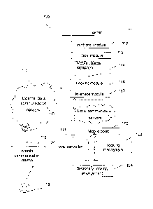
[0032] Fig. 1 illustrates the main components of the theft prevention system
according to some
embodiments of the present invention. The system comprises a server 100 for
managing and
controlling the usage of the plurality of mobile objects such as shopping
cart, enabling anonymous
users a limited usage for predefined time period of the mobile object
optionally within a predefined
area. The server includes a data module 113 for updating the mobile objects
repository 114, a controller
module 112 for monitoring the usage of the mobile objects, a locking module
116 for controlling a
locking mechanism of 122 and interface module 117 for communication with the
user's mobile devices
118 and the local controller 121. Each mobile object 120 is attached by
locking mechanism 122 to a
stationary secure locking arrangement 124. The locking mechanism is
electronically controlled by the
6
CA 02862583 2014-07-24
WO 2013/111131 PCT/IL2013/050062
local controller device 121. Once a mobile object is returned by the user and
locked to the stationary
locking device, the local controller 121 reports the controller server. The
local controller 121 and server
100 can communicate through communication data network 110 such as the
Internet or through local
network in case the server is positioned at the commercial area. The user 119
use his personal mobile
118 device for releasing the mobile object using electronic messaging device
such as SMS or using
dedicated application on a smart phone, in both options the user may read from
the tag of the mobile
device or enter the identifying ID of the tag, such as scanning barcode and
send request for releasing
the mobile object.
[0033] Fig. la illustrates the main components of the theft prevention system
according to other
embodiments of the present invention. The system comprises a server 100 for
managing and
controlling the usage of the plurality of mobile objects such as shopping
cart, enabling anonymous
users a limited usage for predefined time period of the mobile object
optionally within a predefined
area. The server includes a data module 113 for updating the mobile objects
repository 114, a controller
module 112 for monitoring the usage of the mobile objects, a locking module
116 for controlling a
locking mechanism of 122 and interface module 117 for communication with the
local communication
device 118A and the local controller 121. Each mobile object 120 is attached
by locking mechanism
122 to a stationary secure locking arrangement 124. The locking mechanism is
electronically controlled
by the local controller device 121. Once a mobile object is returned by the
user and locked to the
stationary locking device, the local controller 121reports the controller
server.
[0034] The local controller 121 and server 100 can communicate through
communication data network
110 such as the Internet or through local network in case the server is
positioned at the commercial
area.
The local communication device 118A can be integrated part of the local
controller or a separate part
which is connected with the local controller, this local communication device
communicates with an ID
card 120 of the user 119. This local communication may be implemented using
barcode reading, blue
tooth protocol or RF communication or any wireless communication link for
receiving the ID of the
user. According to this embodiment the ID of the mobile object may be derived
from the release order
of the mobile objects which can be determined in the controller server.
Optionally the locking
mechanism may include detection module for reading the ID code of the mobile
object.
Fig. 2 illustrates the process of the data module according to some
embodiments of the present
invention. When adding new mobile object to the system the system is updated
with the data of the new
object which is recorded in the repository 114. The mobile objects status is
changed when receiving an
update from the controller module of releasing an object or when locking a
mobile object (step 212).
7
CA 02862583 2014-07-24
WO 2013/111131 PCT/1L2013/050062
When receiving update of a releasing request for a mobile object, an
association of user's mobile device
and the unique identification codes of the mobile objects is recorded (step
214). Upon receiving a
locking update from the central control module the association between the
user mobile device and
mobile objects is deleted (step 216). In case the limited time period
permission has expired and the user
didn't return the mobile object, the user's mobile phone number is updated in
a "black list". Optionally
users appearing in this list will not be able to receive permission to use
mobile objects in the future.
[0035] Fig. 3 illustrates the process of the central control module according
to some embodiments of
the present invention. The central control module receives updates of mobile
object locking status from
interface module and the local controller. Once receiving update of user's
request of unlocking a mobile
object (step 310) , the control module verifies user request (step 311) before
a release instruction is sent
to the local controller for releasing the selected shopping cart(step 312) and
an update of the mobile
object status message is sent to the data module(step 314) including
association data of the user's
mobile phone number. When the users returns the shopping cart, the cart is
locked to secure locking
arrangement, upon locking an indication is received (step 316). An update
locked status is sent to the
data module (step 318).
[0036] Fig. 4 illustrates the process of the interface module according to
some embodiments of the
present invention. The locking module receives updates of mobile object
locking status from user's
mobile phone and from the local controller. When the user requests to use a
mobile object such as a
shopping cart, he can update the central control module 112 in his request
using his mobile
communication device using one of the following options:
- sending an electronic message such as SMS to a designated number with the
Ill number
appearing on the shopping cart he has selected;
- entering a request to a designated website or a designated smart phone
application;
- reading barcode(optimally 2D bar code) of the mobile object (which
includes the
identification of the mobile object) and transmitting to the server; dialing a
designated
number with the ID code of the mobile object;
[0037] Once the message is received by the interface module, and the request
is verified (step 410) an
update is sent to the central control module 112 of unlock state (step 412)
including association data of
the user's mobile phone number and a releasing instruction is sent to the
local controller 121 (step
413). When the users returns the shopping cart, the cart is locked to secure
locking arrangement, upon
locking an indication is received from the local control module (step 414).
The interface module
updates of the lock status to the central control module (step 416).
Optionally according to the
8
CA 02862583 2014-07-24
WO 2013/111131 PCT/IL2013/050062
embodiment illustrated in Fig.1 a, only the user ID is received from the
communication 118 and the
mobile object device is received from the server.
[0038] Fig. 5 illustrates the process of the locking mechanism according to
some embodiments of the
present invention. The locking mechanism enables to lock at least one mobile
object to the secure
locking arrangement, where the releasing of the mobile object is controlled
electronically by the local
controller device 121. The releasing operation is activated (step 520) once
receiving an instruction from
the local controller device (step 510), which identifies the object to be
released by it's identification
code. Optionally the instruction doesn't include the identification code of
the mobile object and first in
line object is released. Once the object is release a verification message is
sent to the local
controller(step 514). When the users return the mobile objects to the secure
locking arrangement, the
returned mobile objects is identified (step 516) the mobile object is locked
(step 518) and an electronic
indication is automatically sent to the local control module (step 520).
[0039] Fig. 6 illustrates the process of the local control module according to
some embodiments of the
present invention. The module receives unlocking command of a specific mobile
device identified by
its identification code from the central controller module (step 610) and
sends an electronic instruction
to the locking mechanism for releasing the identified mobile object. Upon
receiving indication of
returned locked mobile object and indication message is sent to the interface
module including the ID
of the locked mobile object.
Fig. 7 is a schematic illustration of a first secure locking arrangement
according to some embodiments
of the present invention. Plurality of shopping carts 120 are connected via
locking mechanism 122 to
secure locking arrangement 124. The secure locking arrangement includes a
stand having holes locking
elements 128 (see fig. 9) which are arrange to hook the lockimg elements which
are attached to the
shopping cart. Such arrangement allows locking plurality of carts be stacked
together occupying
minimum space.
[0040] Fig. 8 is a schematic illustration of a second secure locking
arrangement according to some
embodiments of the present invention. Plurality of shopping carts 120 are
connected via locking
mechanism 122 to secure locking arrangement 124. The secure locking
arrangement includes a stand
having a rail, enabling to slide locking elements which are attached to the
shopping carts. Such
arrangement allows locking plurality of carts, stacked together, occupying
minimum space.
[0041] Fig. 9 is a schematic detailed illustration of a first secure locking
arrangement according to
some embodiments of the present invention. This figure illustrates an enlarged
view of the a locking
element in the lock position, a plug element 126 is inserted within a
cylindrical cavity 128 located at
the locking arrangement stand. In a lock state is activated a led 127 on the
stand indicating of the lock
9
CA 02862583 2014-07-24
WO 2013/111131 PCT/IL2013/050062
state.
[0042] Fig. 10 is a schematic detailed illustration of a first secure locking
arrangement according to
some embodiments of the present invention. This figure illustrate an enlarge
view of the a locking
element in the lock position, further showing the inner parts within locking
arrangement, including a
solenoid 132 having solenoid core 130. At a locking operation the solenoid and
the it's core is activated
locking the plug connectors 146 which secure the plug 134 in it's position.
[0043] Figs. 11 and 12 are schematic detailed illustration of a second secure
locking arrangement
according to some embodiments of the present invention.
[0044] Fig. 11 illustrate locking second secure locking arrangement and cart
in an unengaged
position. This locking arrangement integrates rail 146 including three sensors
and two stoppers. The
plug 148 connected to the cart is design to slide within the rail 146, when
sliding the plug locking
element in and out along the rail , the plugl 48 is conveyed through two
stoppers 144a and 14411 for
preventing the user to release more than one cart at a time. rtlie sensors
142a and a142b indicate when
the plug pas through corresponding stoppers 144a and 144 b.
[0045] Fig. 11 illustrate locking second secure locking arrangement and cart
in an engaged position
where the plug 148 slides along the rail 146.
[0046] Figs. 13 and 14 are schematic detailed illustration of a second secure
locking arrangement
according to some embodiments of the present invention. These figures
illustrates the detailed
construction of the sensors the two stoppers, each stopper 144 includes a
solenoid 155 which
encapsulates the stopper button 152, when activating/deactivating in solenoid,
the stopper button
moves is in and out respectfully for blocking/unblocking the plug movement.
[0047] It is to be understood that the phraseology and terminology employed
herein is not to be
construed as limiting and are for descriptive purpose only.
[0048] Figs. 15 is a block diagram illustrating the theft prevention system
according to some
embodiments of the invention.
[0049] The system comprises a server 100 for managing and controlling the
usage of the plurality of
mobile objects such as shopping cart, enabling anonymous users a limited usage
for predefined time
period of the mobile object optionally within a predefined area. The server
includes a data module 113
for updating the mobile objects repository 114, a controller module 112 for
monitoring the usage of the
mobile objects, a restriction mechanism such as a tracking module 111 for
controlling and restricting
the usage of the mobile objects within the restricted rental zone and
interface module 117 for
communication with the user's mobile devices 118 and the local controller 121.
Each mobile object 120
includes a tracking module 111 enabling to communicate with local controller
121. Once a mobile
CA 02862583 2014-07-24
WO 2013/111131 PCT/11,2013/050062
object is returned by the user to the restricted rental zone, the local
controller 121 reports the controller
device. The local controller 121 and server 100 can communicate through
communication data network
110 such as the Internet or through local network in case the server is
positioned at the commercial
area. The user 119 can use his personal mobile 118 device for enabling the
usage of the mobile object
using electronic messaging device such as SMS or using dedicated application
on a smart phone, in
both option the user may read from the tag of the mobile object or enter the
identifying Ill of the tag
and send request for using the mobile object. In case the user don't request
permission to use the mobile
object and the mobile object was tracked out of the restricted rental area
zone, an alarm status is
activated, optionally generating warning sound or the mobile object movement
is disabledo inn nn. In
case the user doesn't return the mobile object to the restricted rental zone
the within predefined lime
period, the alram status is activated.
[0050] According to some embodiments of the present invention the system may
further comprise a at
least one checkup module located at a selling point of a store which rent
shopping carts to be used
within it's facilities. The check module include a communication module for
reading ID of the mobile
object located near by the selling point for verifying that the user which its
mobile phone is associated
with the shopping paid before leaving the store. In case the users returns the
mobile object and no
verification of payment was received from the checkup module the user may be
marked for inspection.
Such check module may enable to prevent thefts.
[0051]
[0052] The principles and uses of the teachings of the present invention may
be better understood with
reference to the accompanying description, figures and examples. It is to be
understood that the details
set forth herein do not construe a limitation to an application of the
invention.
[0053] Furthermore, it is to be understood that the invention can be carried
out or practiced in various
ways and that the invention can be implemented in embodiments other than the
ones outlined in the
description above. It is to be understood that the terms "including",
"comprising", "consisting" and
grammatical variants thereof do not preclude the addition of one or more
components, features, steps,
or integers or groups thereof and that the terms are to be construed as
specifying components, features,
steps or integers.
[0054] If the specification or claims refer to 'an additional" element, that
does not preclude there being
more than one of the additional element. It is to be understood that where the
claims or specification
refer to "a" or "an" element, such reference is not to be construed that there
is only one of that element.
[0055] It is to be understood that where the specification states that a
component, feature, structure, or
characteristic "may", "might", "can" or "could" be included, that particular
component, feature,
11
I
structure, or characteristic is not required to be included. Where applicable,
although state diagrams,
flow diagrams or both may be used to describe embodiments, the invention is
not limited to those
diagrams or to the corresponding descriptions. For example, flow need not move
through each
illustrated box or state, or in exactly the same order as illustrated and
described.
[0056] Methods of the present invention may be implemented by performing or
completing manually,
automatically, or a combination thereof, selected steps or tasks. The term
"method" may refer to
manners, means, techniques and procedures for accomplishing a given task
including, but not limited
to, those manners, means, techniques and procedures either known to, or
readily developed from
known manners, means, techniques and procedures by practitioners of the art to
which the invention
belongs.
[0057] The descriptions, examples, methods and materials presented in the
claims and the specification
are not to be construed as limiting but rather as illustrative only. Meanings
of technical and scientific
terms used herein are to be commonly understood as by one of ordinary skill in
the art to which the
invention belongs, unless otherwise defined. The present invention may be
implemented in the testing
or practice with methods and materials equivalent or similar to those
described herein.
12
CA 2862583 2019-08-08