Note: Descriptions are shown in the official language in which they were submitted.
MULTI-DIRECTIONAL ROLLER ASSEMBLY
RELATED APPLICATIONS
The present invention claims priority to U.S, Provisional Patent Application
Serial
No. 61/592,708, filed January 3 I, 2012.
BACKGROUND
The invention relates generally to power-driven conveyors and more
particularly to
conveyors having actuated, multi-directional rollers for manipulating the
trajectory of articles
through a conveyor system.
Many package- and material-handling applications require that conveyed
articles be
diverted to a side of a conveyor. Two examples are sorting articles off the
side of a belt and
registering articles against the side of the belt. U.S. Patent No. 6.494,312,
"Modular Roller-
Top Conveyor Belt with Obliquely-Arranged Rollers," December 17, 2002, to
Costanzo
discloses a conveyor system in which cylindrical rollers mounted in a conveyor
belt on axles
oblique to the direction of belt travel are actuated by underlying bearing
surfaces on which
the oblique rollers ride as the belt advances in the direction of belt travel.
The contact
between the rollers and the bearing surfaces causes the rollers to rotate as
the belt advances.
The rotation of the oblique rollers pushes articles atop the rollers across
the conveyor belt
toward a side of the conveyor. These oblique-roller belts work extremely well
on planar
bearing surfaces as long as the rollers are arranged to rotate at an angle
between the direction
of belt travel (defined as a roller angle of 0 ) and about 30 or so from the
direction of belt
travel. For roller angles greater than 30 , the rollers slip too much on the
planar bearing
surfaces.
U.S. Patent No. 6,968,941. "Apparatus and Methods for Conveying Objects,"
November 29, 2005, to Fourney describes an improved bearing surface that
accommodates a
much greater range of roller angles. Instead of using a planar bearing
surface, Fourney uses
the outer peripheries of actuating rollers arranged to rotate on axes in the
direction of belt
travel. As the conveyor belt advances, the oblique belt rollers roll on the
underlying actuating
rollers, which are also caused to roll on their axes. Because the bearing
surface on the
periphery is rolling, slip is reduced and greater roller angles can be
accommodated. The
1
CA 2862607 2019-07-29
greater roller angles permit much sharper article-diversion trajectories than
are possible
with a planar bearing surface. But actuating rollers are more expensive and
slightly more
complicated than simple planar bearing surfaces.
U.S. Patent No. 7,588,137, "Conveyor Belt Having Rollers that Displace
Objects,"
September 15, 2009, to Fourney describes a conveyor belt that includes
multiple roller sets
used to divert objects from the conveyor belt. The angles along which articles
can be
diverted from the conveyor are limited.
SUMMARY
The present invention is directed to a multi-directional roller assembly,
comprising: a
frame rotatable about a main axis; and at least one set of two parallel
mutually-actuating
rollers mounted to the frame, each roller having an outer surface in contact
with an outer
surface of the other roller in the set, and rotatable about a minor axis in an
opposite direction
from the other roller in the set, wherein each minor axis is transverse to the
main axis.
The present invention is further directed to a roller plate, comprising: an
upper plate
.. having an array of upper openings; a lower plate having an array of lower
openings
matching the array of upper openings; an array of multi-directional roller
assemblies housed
in the upper and lower openings, each multi-directional roller assembly
comprising a frame
rotatable about a main axis and a set of two parallel rollers mounted to the
frame, each roller
rotatable about a minor axis that is transverse to the main axis in an
opposite direction from
the other roller in the set, and an actuator for orienting at least one of the
multi-directional
roller assemblies relative to the upper plate and lower plate.
The present invention is further directed to a conveyor system, comprising: an
array
of multi-directional roller assemblies, each multi-directional roller assembly
comprising a
frame rotatable about a main axis and a pair of parallel, mutually-actuating
rollers mounted
to the frame, each roller rotatable about a minor axis in an opposite
direction from the other
roller in the pair, wherein the minor axis is transverse to the main axis; and
a driver for
contacting a bottom surface of a multi-directional roller assembly to induce
rotation of at
least one of the frame and the rollers.
The present invention is further directed to a multi-directional roller
assembly,
comprising: a frame rotatable about a main axis; and at least one set of
mutually-actuating
2
CA 2862607 2019-07-29
rollers mounted to the frame, each roller rotatable about a minor axis that is
transverse to
the main axis, wherein an object supported by the frame and rollers will be
directed off the
assembly at an output angle relative to an input force that is twice an input
angle between
the main axis and the input force.
The present invention is further directed to a multi-directional roller
assembly,
comprising: a frame rotatable about a main axis, the frame including axle
nubs; at least one
set of two parallel, mutually-actuating rollers mounted to the frame, each
roller rotatable
about a minor axis that is transverse to the main axis; and a disk-shaped
roller housing for
rota tably mounting the frame, the roller housing including peripheral
openings extending
along the main axis for receiving the axle nubs.
The present invention is further directed to a multi-directional roller
assembly,
comprising: a frame rotatable about a main axis; and a first pair of parallel,
mutually-
actuating rollers mounted to the frame, the parallel, mutually actuating
rollers having outer
surfaces in contact with each other, such that rotation of a first roller in a
first direction about
a first minor axis induces rotation of a second, parallel roller in a second
direction about a
second minor axis, wherein the first minor axis and second minor axis are
transverse to the
main axis.
The present invention is further directed to a multi-directional roller
assembly,
comprising: a frame rotatable about a main axis; a first roller mounted to the
frame and
rotatable about a first minor axis that is nonparallel with the main axis; and
a second roller
mounted to the frame and rotatable about a second minor axis that is
nonparallel with the
main axis, wherein a central portion of the outer surface of the second roller
contacts a
central portion of the outer surface of the first roller so that rotation of
the second roller
induces rotation of the first roller.
The present invention is further directed to a roller plate, comprising: an
upper plate
having at least one opening; a lower plate having at least one opening; and an
array of
multi-directional roller assemblies between the upper plate and lower plate,
each multi-
directional roller assembly comprising a frame rotatable about a main axis and
a first set of
rollers mounted to the frame such that at least a portion of one roller
protrudes through the
upper plate, each roller in each set rotatable about a minor axis that is
nonparallel with the
main axis, wherein the rollers in the first set are mutually-actuating so that
rotation of a first
2a
CA 2862607 2019-07-29
roller induces rotation of a second roller in the set in an opposite direction
from the first
roller in the set.
The present invention is further directed to a conveyor system, comprising: a
roller
plate having an upper surface and a bottom surface; an array of roller
assemblies in the
roller plate, each roller assembly comprising a frame, a first roller
rotatably mounted to the
frame and protruding below the bottom surface and a second roller rotatably
mounted to
the frame and protruding above the upper surface, wherein the first roller and
the second
roller are mutually-actuating with each other; and a conveyor belt extending
below the roller
plate for contacting portions of each of the roller assemblies protruding
below the bottom
surface to actuate the array of roller assemblies.
The present invention is further directed to a conveyor system, comprising: a
conveyor belt for conveying items in a first direction; a diverting plate for
receiving items
from the conveyor belt and selectively diverting items from the first
direction to a second
direction; and a first conveyor belt diverter for diverting the conveyor belt
below the
diverting plate, wherein the conveyor belt forms a driver for the diverting
plate to cause the
diverting plate to selectively divert items.
The present invention is further directed to a conveyor system, comprising: a
roller
assembly having an orientable housing, a top roller protruding from the top of
the
orientable housing for contacting a conveyed item and a bottom roller
protruding from the
bottom of the orientable housing; and a conveyor belt below and in contact
with a
bottommost portion of the bottom roller for inducing rotation in the bottom
roller, the
bottommost portion protruding from the bottom of the orientable housing.
An embodiment of the present invention provides a multi-directional roller
assembly
comprising a rotatable roller frame housing at least one set of mutually-
actuating rollers.
.. The multi-directional roller assembly directs an article supported by the
assembly along a
trajectory determined by the orientation of the multi-directional roller
assembly relative to
an input force. The orientation of the multi-directional roller assembly may
be changed to
change the trajectory. A conveyor system may include an array of multi-
directional roller
assemblies. An actuator controls the orientation of the multi-directional
roller assemblies
individually, and may also control an array of multi-directional roller
assemblies as a group.
2b
CA 2862607 2019-07-29
According to one aspect of the invention, a multi-directional roller assembly
comprises a frame rotatable about a main axis and at least one set of mutually-
actuating
rollers mounted to the frame. Each roller is rotatable about a minor axis that
is transverse to
the main axis.
According to another aspect of the invention, a roller plate comprises an
upper plate
having an array of openings, a lower plate having an array of openings
matching the array
of openings in the upper plate, and an array of multi-directional roller
assemblies housed in
the openings. Each multi-directional roller assembly comprises a frame
rotatable about a
main axis and at least one set of rollers mounted to the frame, each roller
rotatable about a
minor axis that is transverse to the main axis.
According to another aspect of the invention, a conveyor system comprises an
array
of multi-directional roller assemblies, each multi-directional roller assembly
comprising a
frame rotatable about a main axis and at least one set of rollers mounted to
the frame, each
roller rotatable about a minor axis that is transverse to the main axis. A
driver, which may be
a conveyor belt, induces rotation of one of the frame and one set of rollers.
2c
CA 2862607 2019-07-29
CA 02862607 2014-07-23
WO 2013/116431
PCT/US2013/023997
According to another aspect of the invention, a method of directing an article
of
conveyance using a multi-directional roller assembly is provided. The multi-
directional
roller assembly includes a frame rotatable about a main axis and at least one
roller rotatable
about a minor axis that is transverse to the main axis. The method comprises
placing the
article in contact with the multi-directional roller assembly and applying an
input force to
the multi-directional roller assembly at an input angle relative to the major
axis, causing
rotation of at least one of the frame and the roller, such that the article is
pushed from the
multi-directional roller assembly at an output angle that is at least twice
the input angle.
BRIEF DESCRIPTION OF THE DRAWINGS
These aspects and features of the invention, as well as its advantages, are
explained
in more detail in the following description, appended claims, and accompanying
drawings,
in which:
FIG. IA is a perspective view of a multi-directional roller assembly according
to an
illustrative embodiment of the invention;
FIG. 1B is a side view of the multi-directional roller assembly of FIG. 1A;
FIG. 1C illustrates the multi-directional roller assembly of FIGS. 1A and 1B
without
an end cover;
FIG. 2 is a cross-sectional view of a roller set of the multi-directional
roller assembly
of FIGS. 1A-1C along lines A-A;
FIG. 3A is a perspective view of a multidirectional roller assembly including
a roller
housing;
FIG. 3B is a top view of the multidirectional roller assembly of FIG. 3A;
FIG. 3C is a side view of the multidirectional roller assembly of FIG. 3A;
FIG. 3D is a front view of the multidirectional roller assembly of FIG. 3A;
FIG. 4 is an exploded view of the multi-directional roller assembly of FIG.
3A;
FIG. 5 is a perspective view of another embodiment of a multi-directional
roller
assembly;
FIG. 6A is a top view of another embodiment of a multi-directional roller
assembly;
FIG. 6B is a perspective view of the multi-directional roller assembly of FIG.
6A;
FIG. 6C is a side view of the multi-directional roller assembly of FIG. 6A;
FIG. 6D is front view of the multi-directional roller assembly of FIG. 6A;
3
CA 02862607 2014-07-23
WO 2013/116431 PCT/US2013/023997
FIG. 7 is an exploded view of the multi-directional roller assembly of FIG.
6A;
FIG. 8A is a top view of another embodiment of a multi-directional roller
assembly,
including two pairs of rollers;
FIG. 8B is a perspective view of the multi-directional roller assembly of FIG.
8A;
FIG. 8C is a side view of the multi-directional roller assembly of FIG. 8A;
FIG. 8D is front view of the multi-directional roller assembly of FIG. 8A;
FIG. 9 illustrates the multi-directional roller assembly of FIGS. 8A-8D
without an end
cover or housing;
FIG. 10A is a top view of a multi-directional roller assembly when an input
force is
applied perpendicular to the major axis;
FIG. 10B is a side view of the multi-directional roller assembly of FIG. 10A;
FIG. 11A is a top view of a multi-directional roller assembly when an input
force is
applied parallel to the major axis;
FIG. 11B is a side view of the multi-directional roller assembly of FIG. 11A;
FIG. 12A is a top view of a multi-directional roller assembly when an input
force is
applied at a 45 angle to the major axis;
FIG. 12B is a side view of the multi-directional roller assembly of FIG. 12A;
FIG. 13 is a top view of a multi-directional roller assembly when an input
force is
applied at a 30 angle relative to the major axis;
FIG. 14 illustrates the relationship between an input vector, a frame output
vector, a
roller output vector and an assembly output vector for the multi-directional
roller assembly
of FIG. 13;
FIG. 15A is a top view of a roller plate housing an array of multi-directional
roller
assemblies according to an illustrative embodiment of the invention;
FIG. 15B is a perspective view of the roller plate of FIG. 15A;
FIG. 15C is a top view of the roller plate of FIG. 15A with the top plate
removed;
FIG. 16 is a detailed view of the roller plate of FIG. 15A with the top plate
removed
and showing a rack gear for orienting the multi-directional roller assemblies;
FIGS. 17A is perspective view of a conveyor system employing a plurality of
roller
plates housing arrays of multi-directional roller assemblies;
FIG. 17B is a top view of the conveyor system of FIG. 17A;
4
CA 02862607 2014-07-23
WO 2013/116431 PCT/US2013/023997
FIG. 17C is a partial cross-sectional view of the conveyor system of FIG. 17B
along
lines B-B;
FIG. 18 is a schematic view of a conveyor system including a drop-in roller
plate
housing an array of multi-directional roller assemblies;
FIG. 19A is a top view of a roller plate housing an array of multi-directional
roller
assemblies according to another embodiment of the invention;
FIG. 19B is a side view of the roller plate of FIG. 19A;
FIG. 19C is a perspective view of the roller plate of FIG. 19A;
FIG. 19D is a front view of the roller plate of FIG. 19A;
FIG. 20A is a top view of a conveyor system employing the roller plate of FIG.
19A;
FIG. 20B is a side view of the conveyor system of FIG. 20A;
FIG. 21 is a detailed view of section 312 of FIG. 20B;
FIG. 22 is a top view of an alternate embodiment of a conveyor system having
multiple driving conveyor belts and employing a plurality of roller plates
housing arrays of
multi-directional roller assemblies;
FIGS. 23A and 23B are top and perspective views of a roller plate that employs
gears
to orient an array of multi-directional roller assemblies housed therein;
FIG. 24 is a detailed view of region 615 of FIG. 23A, showing an engagement
between
a gear rack and roller assembly housing in the roller plate of FIGS. 23A and
23B;
FIG. 25A and 25B are top and side views of a roller plate that employs a cam
ring to
orient an array of multi-directional roller assemblies housed therein;
FIGS 26A-26D illustrate a multi-directional roller assembly including an
offset cam
ring, suitable for use in the roller plate of FIGS. 25A and 25B;
FIGS. 27A-27C are top, side and bottom views of a roller plate employing spur
gears
to orient an array of multi-directional roller assemblies housed therein;
FIG. 28 illustrates a conveyor system employing roller plates housing an array
of
multi-directional roller assemblies;
FIG. 29 is a detailed view of region 920 of the conveyor system of FIG. 28;
FIGS. 30A and 30B are top and side views of a conveyor system employing roller
plates housing an array of multi-directional roller assemblies to align
articles of conveyance;
FIG. 31 is a detailed view of region 1122 of the conveyor system of FIG. 30A;
5
CA 02862607 2014-07-23
WO 2013/116431 PCT/US2013/023997
FIGS. 32A and 32B are top and side views of a conveyor system employing roller
plates housing an array of multi-directional roller assemblies to divert
articles of conveyance
to one of two outfeed conveyors;
FIG. 33 illustrates a conveyor system employing roller plates housing an array
of
multi-directional roller assemblies to rotate an article of conveyance;
FIG. 34 illustrates a conveying system employing arrays of multi-directional
roller
assemblies for changing the direction of conveyance while maintaining the
leading edge of a
conveyed article;
FIG. 35 is a detailed view of region 1411 of the conveyor system of FIG. 34;
and
FIG. 36 is a detailed view of region 1412 of the conveyor system of FIG. 34.
DETAILED DESCRIPTION
A conveyor system includes an array of multi-directional roller assemblies.
Each
multi-directional roller assembly includes a rotatable frame and rollers for
supporting
articles of conveyance and for manipulating the trajectory of the articles
through the
conveyor system. In addition to an array of multi-directional roller
assemblies, a conveyor
system may include an actuator that may control the orientation of the multi-
directional
roller assemblies individually, as well as control an array of multi-
directional roller
assemblies as a group. The invention will be described below relative to
certain illustrative
embodiments.
An embodiment of a multi-directional roller assembly suitable for use in a
conveyor
system is shown in FIGS. 1A-1C. The multi-directional roller assembly 10
includes a frame
12 rotatable about a main axis 14. The frame 12 includes axle nubs 18
extending along the
main axis 14. The axle nubs 18 are formed in an end cover 19. The frame
further includes
openings 16 for receiving rollers 28. At least one set of mutually-actuating
rollers is mounted
to the frame 12 in the openings 16. The illustrative embodiment shows three
sets 22, 24, 26 of
mutually-actuating rollers disposed along the length of the frame 12 at
different
orientations, each set comprising a pair of parallel, substantially elliptical-
shaped rollers 28.
The illustrative frame 12 includes roller axle openings 31 for receiving
roller axles 32
extending through the rollers along a minor axis 34. Each roller 28 is
rotatable about a minor
axis 34, defined by the axles 32. Each minor axis 34 is oriented transverse to
the main axis of
rotation 14. (As used in this description, transverse axes are axes that are
not parallel to each
6
CA 02862607 2014-07-23
WO 2013/116431 PCT/US2013/023997
other, which includes skew axes that lie in different planes.) As shown in
FIG. 1B, the
outside surfaces 29 of the rollers 28 extend beyond the frame 12 of the
assembly. In one
embodiment, each roller 28 is a flat-ended ellipsoid with axles extending
through a central
passageway, but the rollers may have any suitable shape and configuration. In
another
embodiment, the rollers 28 include axle nubs for rotatable mounting in the
frame 12. Other
suitable means for rotatably mounting the rollers to the frame may be used.
The rollers 28 in each set may mutually-actuate each other through any
suitable
means. For example, as shown in FIG. 2, roller contact between the outside
surfaces 29 of
associated rollers 28 causes transfer of rotational force from one roller to
the other. In this
manner, when one roller is driven in a first direction, indicated by arrow 36
in FIG. 1C, the
associated roller rolls in an opposite direction, indicated by arrow 37 in
FIGS. 1C and 2.
Alternatively, the rollers may mutually-actuate through gears, magnetic
actuation, or
another suitable means. For example, the surface of each roller may include
teeth, with the
teeth engaging each other to allow mutual-actuation. The material forming the
outer
surfaces of the rollers 28 may composed of a resilient or at least pliable
material to reduce
slip between the rollers. In another embodiment, external gears connected to
the rollers may
allow mutual-actuation of the rollers.
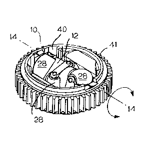
As shown in FIGS. 3A-4, a multi-directional roller assembly 10 may further
include a
roller housing 40 for rotatably mounting the frame 12 and rollers 28.
Preferably, the frame 12
spins freely about the major axis 14 within the housing 40. The illustrative
housing 40 is a
round, disk-shaped housing with a central opening 42 for receiving the frame
12. As shown
in FIG. 4, the illustrative roller assembly includes bearings 45 and axle
inserts 44 that are
insertable in slots 47 in the housing. The bearings 45 and axle inserts 45
receive the axle nubs
18 of the frame 12 to rotatably mount the frame 12 to the housing 40. Salient
portions of the
frame 12 and rollers 28 protrude outside the top and bottom surfaces 48, 49 of
the housing
40.
Each set of rollers 28 is oriented at a different angle relative to the frame
12.
Preferably, the sets of rollers 28 are equally spaced around the frame
periphery, with the
summation of the angles between a series of consecutive minor axes of rotation
34 equal to
90 . In the version shown in FIGS. 1A-4, the frame 12 houses three sets of
roller pairs offset
by 45 relative to each other. In this manner, at least one set of rollers at
all times extends
7
CA 02862607 2014-07-23
WO 2013/116431
PCT/US2013/023997
beyond the top and bottom surfaces 48, 49 of the housing, regardless of the
rotational
orientation of the frame 12.
In the embodiment shown in FIGS. 3A-4, the housing 40 further includes teeth
41
about the perimeter or a portion of the perimeter. The teeth 41 engage gears
or another
device to orient the roller assembly, as described below.
FIG. 5 shows another embodiment of a multi-directional roller assembly 110.
The
roller assembly 110 include a disc-shaped housing 140 having an opening 142
for receiving a
rotatable frame 112 housing mutually-actuating rollers 128. The frame 112
includes axle
nubs 118 mounted in an opening 144 in the housing 140. The frame 112 rotates
about an axis
114 within the housing 140. The frame 112 is more cylindrical than the frame
12 of FIGS. 1-4,
but the principles of operation are substantially the same.
Another embodiment of a multi-directional roller assembly 210 is shown in
FIGS.
6A-7. The multi-directional roller assembly 210 includes a rotatable frame 212
for mounting
one or more sets of mutually-actuating rollers 228. The frame 212 includes a
plurality of
disk-shaped ribs 215, and is rotatable about a major axis 214. Each set of
mutually actuating
rollers 228 is mounted in a space between ribs 215. The frame 212 further
includes axle nubs
218 extending along the main axis of rotation 214 of the frame 212. In the
embodiment of
FIGS. 6A-7, each roller 228 comprises a central cylindrical roller 227,
rotatable about a minor
axis 234, and two side cones 229. Each central cylindrical roller 227 engages
by contact a
corresponding roller in the set, such that rotation of one roller in the set
causes rotation of
the corresponding roller in the set, preferably in an opposite direction.
Other suitable means
for mutual roller actuation, such as gears or magnets, may be used.
The multi-directional roller assembly 210 further includes a housing 240 for
rotatably
mounting the frame 212 and rollers 228. As shown in FIG. 7, the housing 240
may comprise
two mating halves 240a and 240b. The illustrative housing 240 is a disk-
shaped, with a
central opening 242 for rotatably receiving the frame 212, and axle openings
244 for
receiving axle nubs 218. Bearings 243 and washers 245 facilitate rotation of
the frame 212
when mounted in the housing 240. The housing 240 of FIGS. 6A-7 is shaped, with
a
contoured upper surface 248 and a contoured lower surface (not shown).
As shown in FIGS. 8A-9, a multi-directional roller assembly 310 may include
two
sets of mutually-actuating rollers 328, each oriented 90 relative to each
other on the
periphery of a frame 312 mounted in a housing 340. The frame 312 includes axle
nubs 318
8
CA 02862607 2014-07-23
WO 2013/116431
PCT/US2013/023997
formed in an end cover 319 and extending along a main axis 314. Each set of
rollers 328 in
the embodiment of FIGS. 8A-9 comprises a pair of parallel, rotatable rollers
having outer
surfaces that contact each other to induce rotation in one roller about a
transverse minor axis
upon rotation of the other roller, though other means for inducing rotation in
a
corresponding roller may be used.
A multi-directional roller assembly may include any suitable number of sets of
mutually-actuating rollers disposed along the length of the frame at various
orientations.
Each set may comprise any suitable number of rollers, and is not limited to a
pair of
mutually-actuating rollers in each set.
A multi-directional roller assembly can be used to manipulate the orientation
and
trajectory of an article of conveyance placed on the multi-directional roller
assembly. The
multi-directional roller assembly can redirect a single input vector to an
unlimited angular
output vector, capable of directing an article placed on the multi-directional
roller assembly
in any suitable direction. For example, referring to FIGS. 10A-10B, an input
force applied to
the bottom side of a multi-directional roller assembly 110, indicated by arrow
61, that is
perpendicular to the major axis 114 causes the frame 112 to rotate within the
housing 140
about the major axis 114 in the direction of output frame vector 62. The
rollers 28 do not
rotate about the minor axes 34 under the influence of the input force 61.
Thus, the output
vector 62 of the assembly is 1800 from the input vector 61. When the roller
assembly 210 is
positioned with the major axis 214 extending 90 relative to the input vector
61, the roller
assembly will push an article placed on top of the frame 212 in the direction
indicated by the
output vector 62, or 180 relative to the input vector 61.
Referring to FIGS. 11A-11B, an input force applied to the bottom side of the
assembly 110 that is parallel to the major axis 114 (i.e., oriented at 0 ) and
perpendicular to at
least one of the minor axes 134 will create a different output vector. The
input force,
indicated by vector 63, will cause rotation of one set of rollers 128, without
driving the frame
112. In the embodiment shown in FIG. 11A and 11B, a first set 122 of rollers
128 is actuated
due to the orientation of the frame 112. As shown, the input vector drives a
first roller 128a
of the first set 122 in a first direction 136, causing rotation of the second
roller 128b in a
second direction 137. The rotation of the second roller 128b creates an output
vector 64 that
is parallel to the input vector 63, which propels an article placed on the
frame 112 in the
direction of the output vector 64. The set of rollers 128 that is actuated
depends on the
9
CA 02862607 2014-07-23
WO 2013/116431 PCT/US2013/023997
orientation of the frame 112 when the input force is applied. If the frame 112
is oriented such
that the middle set of rollers is disposed in a substantially vertical
orientation, with the
bottom roller in contact with the input force, then the middle set will
actuate to create the
output vector 64. If the frame is oriented with the third set of rollers
rotated into a
substantially vertical orientation, the third set actuates to create the
output vector 64. Two or
more sets of rollers 128 may actuate at the same time to create the output
vector 64.
Referring to FIGS. 12A-12B, an input force that is oblique to both the major
axis 114
and minor axes 134 causes rotation of both the rollers 128 and roller frame
112 to create an
output vector that is a combination of the output vectors of the frame 112 and
the rollers 128.
In the embodiment of FIGS. 12A and 12B, the input vector 71 indicative of an
input force is
oriented 45 relative to the major axis 114. The force along input vector 71
causes rotation of
the frame 112 about the major axis 114 to create a frame output vector 72 that
is
perpendicular to the axis 114. The input vector 71 also causes rotation of one
or more sets of
the rollers 128 to create a roller output vector 74 that is perpendicular to
the minor axis 34.
The combined output vector 76 extends 90 relative to the input vector 71, so
that an object
placed on the assembly 110 will be directed off the assembly at a 90 angle
relative to the
input force 71.
A desired output angle of an object disposed on the multi-directional roller
assembly
may be achieved through orienting a multi-directional rollers assembly at a
particular angle
relative to the input force. The illustrative assembly produces a 1:2 ratio
between the angular
input vector and the angular output vector. Other ratios may be contemplated.
When the
input vector changes by 90 , the resultant output vector will change by 180 .
For example, as shown in FIG. 13, when a multi-directional roller assembly 110
is
oriented at a 30 angle relative to an input vector 81, the output vector 83,
which is a
combination of the frame output vector 85 and the roller output vector 86,
will extend at 60
(twice the input angle) relative to the input vector 81. FIG. 14 illustrates
the relationship
between the input vector 81, the frame output vector 85, the roller output
vector 86, and the
overall output vector 83 for the entire assembly. An input vector 81 extending
30 relative to
the major axis 114, will create a frame output vector 85 that is perpendicular
to the axis 114
and equal in magnitude to half the input vector (sin 30 ). The input vector 81
also creates a
roller output vector 86 that extends parallel to the major axis 114 and equal
in magnitude to
0.866 of the input vector 81 (cos 30 ). When added together, the frame output
vector 85 and
CA 02862607 2014-07-23
WO 2013/116431 PCT/US2013/023997
roller output vector 86 create the assembly output vector 83, extending at 600
relative to the
input vector 81 and equal in magnitude to the input vector 81. Therefore, an
object placed on
the assembly 110, which is oriented at a 30 angle relative to the input
vector 81, will be
diverted off the assembly at an angle of 60 from the input force acting on
the assembly.
In one application, an array of multi-directional roller assemblies may be
mounted in
a roller plate to form a diverting roller plate for articles of conveyance.
For example, as
shown in FIGS. 15A-15C, a roller plate 300 capable of diverting objects may
comprise an
array of multi-directional roller assemblies 10 mounted between an upper plate
301 and a
lower plate 302. The rollers 28 and frames 12 of the roller assemblies
protrude through
openings in the upper plate 301 and lower plate 302. The array of roller
assemblies may have
any suitable size, shape, number of roller assemblies or configuration. FIG.
16 shows the
roller plate 300 with the top plate 301 removed. As shown, the roller plate
300 includes small
spur gears 306 between the multi-directional roller assemblies 10. The spur
gears 306 engage
the teeth 41 on the perimeter of the roller assemblies, connecting the
assemblies together. A
rack gear 307 or other suitable actuation means extends along the side of the
roller plate 300,
engaging the outermost roller assemblies. A drive gear 308 engages the rack
gear 307. An
actuator rotates the drive gear 308 to impart motion on the rack gear 307,
which causes
rotation of the assemblies as a group and allowing controlled orientation of
the multi-
directional roller assemblies 10 relative to the upper plate 301 and lower
plate 302. Thus, the
entire array of roller assemblies may be oriented at a selected angle to
control the trajectory
of an article 309 placed on the roller plate 300.
Any suitable means for orienting a multi-directional roller assembly in a
selected
orientation relative to an input force to control an output trajectory may be
used. For
example, magnets, motors or other types of gears may be used to orient a multi-
directional
roller assembly.
As shown in FIGS. 17A-17C, a roller plate 300 housing an array of multi-
directional
roller assemblies may be implemented in a conveying system 400 for conveying
products
and may have a number of useful applications in the conveying system. The
conveying
system 400 includes a frame 401 and one or more conveyor belts 405 trained
around rollers
and¨or sprockets. The conveyor belt 405 conveys articles to the roller plate
300 and transfers
articles onto the roller plate 300. The conveyor belt 405 is diverted below
the roller plate 300
by rollers 407. Below the roller plate 300, the conveyor belt 405 forms a
driver for applying
11
CA 02862607 2014-07-23
WO 2013/116431 PCT/US2013/023997
an input force along a selected direction to actuate the multi-directional
roller assemblies 10,
as shown schematically in FIG. 18. Alternatively, the rollers 28, the frame 12
or both may be
actively driven through a motor, magnets, gears or other suitable means.
An actuator 402 controls the orientation of the roller assemblies in the
roller plate
300. The orientation of the roller assemblies relative to the conveyor belt
405 determines the
output trajectory of an article 309 placed on top of the roller plate.
The conveyor belt 405 is diverted back up at the end of the roller plate 300
to receive
and convey articles away from the roller plate 300.
The conveyor belt 405 may be a flat belt, a belt with integrated rollers, a
belt with
integrated balls, or any other suitable type of conveyor belt.
The belt 405 may be selectively engageable and disengageable with the multi-
directional roller assemblies on the underside of the roller plate through any
suitable
actuation means.
The invention is not limited to the use of a conveyor belt as a driver for a
multi-
directional roller assembly, and other suitable drivers may be used.
FIGS. 19A-19D show another embodiment of a roller plate 320 housing an array
of
multi-directional roller assemblies 10 according to another embodiment of the
invention.
The roller plate 320 comprises an upper plate 321 having openings 331 for the
roller
assemblies and a lower plate 322 having openings for the roller assemblies,
such that salient
portions of each roller assembly protrude above the upper plate 321 and below
the lower
plate 322. In the embodiment shown in FIGS. 19A-19D, the roller plate 320
includes eight
roller assemblies each oriented similarly, but the invention is not limited to
the illustrative
configuration.
Referring to FIGS. 20A, 20B and 21, another embodiment of a conveying system
500
employs a plurality of roller plates 320 housing multi-directional roller
assemblies 10. The
conveying system 500 comprises an array of multi-directional roller assemblies
for directing
products in a selected direction. The array may comprise a plurality of roller
plates 320, each
roller plate 320 housing an array of multi-directional roller assemblies 10.
The conveying
system 300 further includes a driver, illustrated as a conveyor belt 330
moving in the
direction of the arrow 331, for applying an input force along a selected
direction to actuate
the multi-directional roller assemblies 10. Alternatively, the rollers 28, the
frame or both may
be actively driven through a motor or other suitable means.
12
CA 02862607 2014-07-23
WO 2013/116431 PCT/US2013/023997
An actuator 340 controls the orientation of the multi-directional roller
assemblies
relative to the conveyor belt 330. The actuator 340 may rotate the entire
roller plate 320 and
change the orientations of each array of multi-directional roller assemblies
to change the
orientation of the conveyance. Alternatively, an actuator may control a single
multi-
directional roller assembly. As previously described, changing the orientation
of the multi-
directional roller assembly changes the output vector of an article placed on
the roller
assembly. The actuator 340 may be an electric, pneumatic, or other suitable
type of actuator.
As shown in FIG. 21, the conveyor belt 330 contacts the frame 12 and exposed
roller
28 of the assembly 10 to drive the multi-directional roller assembly 10,
causing rotation of
the frame 12, the rollers 28 or both. Each multi-directional roller assembly
10 is housed in a
roller plate between an upper plate 321 and a lower plate 322. Depending on
the orientation
of the assembly 10, an article placed on the roller assembly 10 will be
directed in an output
direction that extends at an output angle relative to the conveyor belt
direction 331 that is
twice the angle at which the major axis 14 of the roller assembly 10 extends
relative to the
conveyor belt direction 331.
As shown in FIG. 22, a conveyor system 500 including an array of multi-
directional
roller assemblies may include a plurality of conveyor belts 332, 333, 334 for
driving the
multi-directional roller assemblies. In the embodiment of FIG. 22, multiple
actuators 340'
may be used to change the orientations of the roller plates 320 housing multi-
directional
roller assemblies relative to the conveyor belts 332, 333, 334.
The conveyor system may employ any suitable means for controlling the angular
orientation of the multi-directional roller assemblies to control the
trajectory of articles
conveyed through the system.
FIG. 23A and 23B illustrates an approach for orienting an array of multi-
directional
roller assemblies. As shown in FIGS. 23A and 23B a roller plate 600 suitable
for
implementing in a conveyor system includes an array of multi-directional
roller assemblies
10 housed between an upper plate 621 and a lower plate 622. Each roller
assembly housing
40 includes a pinion gear 640 for engaging a gear rack 650 on the upper plate
621. The gear
rack 650 may alternatively be located on the lower plate 622 or between the
upper plate 621
and lower plate 622. An input actuator (not shown) selectively moves the gear
rack 650,
which causes each multi-directional roller assembly 10 to rotate relative to
the upper plate
621 and lower plate 622. FIG. 24 is a detailed view section 615 of FIG. 23A,
showing the gear
13
CA 02862607 2014-07-23
WO 2013/116431 PCT/US2013/023997
rack 650 engaging the pinion gear 440 on the periphery of the assembly housing
40 to
control the orientation of the multi-directional roller assemblies.
According to another embodiment of the invention, shown in FIGS. 25A-25B and
26A-26D, a camming action may be used to orient an array of multi-directional
roller
assemblies. FIGS. 25A and 25B illustrate a roller plate 700 including an array
of multi-
directional roller assemblies 710. The roller plate 700 includes a upper plate
711, a lower
plate 712, and a cam plate 713 laced between the upper and lower plate. As
shown in FIGS.
26A¨D, the roller housing 740 for each roller assembly 710 may include an
upper plate
centering ring 741 for centering the assembly within the upper plate 711, a
lower plate
centering ring 742 for centering the assembly within the lower plate 712 and a
cam plate ring
743. The cam plate ring 743 has an axis 745 that is offset from the rotational
axis 746 of the
housing 740. An actuator may selectively rotate the cam plate 713, which will
cause rotation
of the roller assemblies 710 mounted in the roller plate 710 as a group, as
indicated by
arrows 760, allowing controlled orientation of the multi-directional roller
assemblies relative
to the upper plate 711 and lower plate 712.
FIGS. 27A, 27B, and 27C illustrate a roller plate 800 including an array of
multi-
directional roller assemblies 10 according to another embodiment of the
invention. The
illustrative plate 800 is circular and houses seven roller assemblies 10 in
three rows. The
plate 800 includes an upper plate 811 and lower plate 812 for mounting the
roller assemblies
10. Each assembly housing 40 includes gear teeth 41 disposed about the
perimeter to create a
large spur gear. Secondary smaller spur gears 842 are disposed between the
multi-
directional roller assemblies. A driven gear 843 is coupled to a rotary
actuator. When the
rotary actuator rotates the driven gear 643, the gears 642, 643 and gear teeth
641 transmit the
rotational motion to all of the roller assemblies, causing rotation of the
assemblies as a group
and allowing controlled orientation of the multi-directional roller assemblies
10 relative to
the upper plate 811 and lower plate 812.
FIG. 28 illustrates a conveying system 900 including a plurality of roller
plates 910,
each housing an array of multi-directional roller assemblies 10. The
illustrative conveying
system 900 is used to change the orientation of an article of conveyance. The
conveying
system 900 includes a frame or housing 901 and a plurality of circular roller
plates 910, each
housing an array of multi-directional roller assemblies 10. A conveyor belt
930 running
below the roller plates 910 drives the multi-directional roller assemblies 10.
Each roller plate
14
CA 02862607 2014-07-23
WO 2013/116431 PCT/US2013/023997
910 includes an upper plate 921 and a lower plate 922 as shown in detail in
FIG. 29. The
lower plate 922 includes gear teeth 923 about its periphery for engaging a
spur gear 925. An
actuator 940 selectively rotates the spur gear 925 to change the orientation
of the array of
multi-directional roller assemblies. While the embodiments of FIGS. 28 and 29
show gear
teeth 923 on the lower plate 922 of the roller plate 910, the upper plate 921
may also or
alternatively include gear teeth for engaging a gear to change the orientation
of the roller
plate 910.
A multi-directional roller assembly 10 may perform a number of different
functions,
such as, but not limited to, sortation, alignment, switching, and turning of
articles. For
example, a plurality of multi-directional roller assemblies may be used to
sort articles
passing through a conveying system with minimum collisions between the
articles. To sort
the articles, the multi-directional roller assemblies are selectively rotated
in groups arrayed
along the conveying system's carryway. A conveyor belt or other driver runs
below the
multi-directional roller assemblies. A control system creates an image of an
incoming article
of conveyance, computes trajectories along the system for each article, and
orients the multi-
directional roller assemblies according to the trajectories to orderly and
rapidly divert
articles from the carryway.
Another application involves use of a multi-directional roller assembly to
align
articles, as shown in FIGS. 30A, 30B, and 31. The alignment system 1100
includes an array of
roller plates 1110, each housing an array of multi-directional roller
assemblies 10, for
translating or rotating and registering an article against a fixed object. The
multi-directional
roller assemblies 10 support an article of conveyance, illustrated as a
package 1170, that
travels through the system. The multi-directional roller assemblies are
oriented at an oblique
angle to the direction 1131 of a driving conveyor belt 1130, as shown in FIG.
31. The package
1170 being supported by the roller assemblies 10 will translate across the
width of the
system 1100 in the direction of arrows 1186 until contact with a fixed object,
illustrated as a
fixed rail 1150. The package 1170 will align to the fixed object 1150.
As shown in FIGS. 32A and 32B, arrays of multi-directional roller assemblies
may be
used in a switch 1202 for a conveying system 1200. The switch 1202 diverts
articles 1270
from one or more infeed conveyors 1204, moving in the direction of arrow 1211
to two or
more outfeed conveyors 1206, 1208. The multi-directional roller assemblies 10
are housed in
roller plates 1210 arranged in an array, and a drive conveyor 1230 contacts
the rollers in the
CA 02862607 2014-07-23
WO 2013/116431 PCT/US2013/023997
roller plates to convey articles across the roller plates 1210. An actuator
controls the
orientation of each roller plate 1210 to control the trajectories of articles
in the system and
distribute the articles to either the first outfeed conveyor 1206 or the
second outfeed
conveyor 1208.
As shown in FIG. 33, arrays of multi-directional roller assemblies may be used
to
selectively rotate an article in a conveying system. An article rotator in a
conveying system
1300 includes a plurality of article-supporting roller plates 1310, each
including an array of
multi-directional roller assemblies 10. An infeed conveyor 1304 conveys
articles 1370 to the
roller plates 1310, and an outfeed conveyor 1306 conveys rotated articles away
from the
.. roller plates 1310. A drive conveyor 1330 drives the rollers in the multi-
directional roller
assemblies to propel the articles through the system at a selected trajectory.
When an article
1370 is located entirely on a single roller plate 1310, an actuator
selectively rotates the entire
roller plate to a desired angle, which rotates the article 1370 as well. The
size of each roller
plate 1310 depends on the size of the largest article to be rotated, as the
roller plate should
.. support the article to be rotated. The multi-directional roller assemblies
may be rotated in
opposite directions to maintain proper flow of articles through the conveying
system.
FIG. 34 illustrates a conveying system 1400 employing arrays of multi-
directional
roller assemblies for changing the direction of conveyance while maintaining
the leading
edge of a conveyed article. The system 1400 includes an array of roller plates
1410, each
.. comprising an array of article-supporting multi-directional roller
assemblies 10. The system
1400 further includes an input conveyor 1404 and a plurality of output
conveyors 1406, 1407,
1408 extending in different directions. A driving conveyor 1430 extends below
the roller
plates 1410 for driving the rollers in the multi-directional roller assemblies
10. At the
downstream end 1411 of the array of roller plates 1410, the multi-directional
roller
assemblies are oriented to propel an article 1470 in contact with the
assemblies forward, as
shown in FIG. 35. At the downstream end, the multi-directional roller
assemblies 10 are
oriented with the main axes 14 perpendicular to the direction of travel 1431
of the drive
conveyor 1430 so that the direction of travel 1480 of articles contacting the
downstream
assemblies 10 is opposite and parallel to the direction of travel 1431 of the
drive conveyor
.. 1430, thereby pushing the articles 1470 forward. At the upstream end 1412,
the multi-
directional roller assemblies are selectively oriented to direct an article in
the direction of
arrows 1486 onto one of the three output conveyors 1406, 1407, 1408, as shown
in FIG. 36.
16
CA 02862607 2014-07-23
WO 2013/116431 PCT/US2013/023997
Depending on their orientation, which may be controlled through any suitable
means as
previously described, the multi-directional roller assemblies 10 in the
upstream end 1412,
direct an article forward onto the first output conveyor 1406, to the side and
back against a
fixed side guard 1470 to direct the article down the second output conveyor
1407 or to the
other side and back against another fixed side guard 1471 to direct the
article down the third
output conveyor 1408.
A multi-directional roller assembly or an array of multi-directional roller
assemblies
may be used in any suitable system and any suitable means may be used to
control the
orientation of the multi-directional roller assemblies in order to control the
trajectory of an
article.
As these few examples suggest, the scope of the invention is meant to be
defined by
the claims and not limited to the details of the described versions.
What is claimed is:
17