Note: Descriptions are shown in the official language in which they were submitted.
CA 02862789 2014-07-08
-1-
DESCRIPTION
Title of Invention: RADIO TERMINAL, RADIO COMMUNICATION
SYSTEM, AND RADIO COMMUNICATION METHOD
Technical Field
The embodiments discussed herein relate to a radio
terminal that performs radio communication, a radio
communication system, and a radio communication method
thereof.
Background Art
The cellular mobile communication has evolved from
the UMTS (Universal Mobile Telecommunication System) into
the LTE (Long Term Evolution). In the LTE, the system
based on the OFDM (Orthogonal Frequency Division
Multiplexing) is specified as the radio access technology
and high-speed radio packet communication with a downlink
peak transmission rate of 100 Mb/s or more and an uplink
peak transmission rate of 50 Mb/s or more is enabled.
The 3GPP (3rd Generation Partnership Project),
which is an international standardization organization,
has currently started examinations of the LTE-A (LTE-
Advanced) based on the LTE toward realization of higher-
speed communication. The LTE-A aims at a downlink peak
transmission rate of 1 Gb/s and an uplink peak
transmission rate of 500 Mb/s and various new technologies,
CA 02862789 2014-07-08
-2-
such as the radio access system and the network
architecture, are under study (for example, see NPTL 1 to
NPTL 3). On the other hand, the LTE-A is the system based
on the LTE, and therefore, it is important to maintain
backward compatibility.
In the LTE or LTE-A, as the operation in the idle
mode of a radio terminal, cell selection is specified.
Specifically, cell selection and cell reselection are
specified (for example, see NPTL 4 and NPTL 5).
The cell selection is performed when the radio
terminal turns on the power and a PLMN (Public Land Mobile
Network: mobile network operator) is selected. As the cell
selection, cell selection (initial cell selection)
performed by a radio terminal without knowing information
of a cell and cell selection (stored information cell
selection) performed by a mobile station with knowledge of
information of a cell are specified.
In the cell selection, a radio terminal measures
radio quality and selects a cell of good radio quality as
a serving cell and camps on a network. More specifically,
if the cell selection criteria "S" determined by RSRP
(Reference Signal Received Power) and RSRQ (Reference
Signal Received Quality) are satisfied, it is possible to
camp on the cell (for example, see NPTL 4). The radio
terminal may receive an incoming call by camping on the
network. The cell reselection is performed in order to
detect a cell of better radio quality and when better
CA 02862789 2014-07-08
-3-
radio quality is detected, the radio terminal camps on the
cell.
Radio measurement in the idle mode is specified in
order to detect a cell of better radio quality (for
example, see NPTL 5). In the idle mode, it is needed to
achieve a balance between power consumption of the radio
terminal and accuracy of radio measurement.
For example, if the frequency of measurement is
reduced in order to suppress power consumption, the
accuracy of measurement deteriorates and there occurs a
case where it is not possible to camp on an appropriate
cell. On the other hand, if the frequency of measurement
is increased in order to improve the accuracy of
measurement, power consumption increases. In view of this
point, DRX (Discontinuous Reception) is specified (for
example, see NPTL 5).
There are cases where a DRX cycle value of the DRX
is acquired by broadcast information broadcasted by the
base station and where it is set by the NAS (Non Access
Stratum), which is an upper layer. The radio terminal
performs measurement at least once for each DRX and
samples the radio quality. The radio terminal then
averages the radio quality according to sampling intervals
specified by the function of the DRX and then calculates a
measured value of the radio quality.
Further, the radio terminal in the idle mode
periodically monitors a paging signal in order to detect
CA 02862789 2014-07-08
29403-12
-4-
an incoming call. In the radio terminal, as in the case of the
measurement described above, if the frequency of monitoring of
a paging signal is reduced, a communication delay occurs and if
the frequency of monitoring of a paging signal is increased,
power consumption increases. Therefore, it is specified that
monitoring of a paging signal is performed only once within the
DRX cycle (for example, see NPTL 4).
As described above, it is possible for the radio
terminal to perform cell selection and incoming call detection
in consideration of power consumption by performing measurement
and monitoring of a paging signal within the DRX cycle, which
is the cycle of measurement.
Citation List
Non-Patent Literature
NPTL 1: 3GPP TR36.913 V9Ø0
NPTL 2: 3GPP TR36.912 V9.3.0
NPTL 3: 3GPP TS36.300 V10.4.0
NPTL 4: 3GPP TS36.304 V10.2.0
NPTL 5: 3GPP TS36.133 V10.3.0
Summary of Invention
It is specified that decision of whether or not to
perform measurement and cell selection is performed at least
once for each DRX cycle. Further, it is specified that sample
values (specifically, values of RSRP and RSRQ) of the radio
quality obtained by measurement are filtered and averaged where
CA 02862789 2016-03-07
29403-12
-5-
the sample values are spaced by at least half of the DRX duration
when calculating a measured value of measurement (for example,
see NPTL 5).
Therefore, if the DRX cycle is increased in order to
suppress power consumption of the radio terminal, the sampling
interval of measurement increases and there has been such a
problem that the accuracy of measurement deteriorates.
According to an aspect of the present invention, there
is provided a radio terminal that performs radio communication
with a base station, comprising: a communication unit configured
to perform radio measurement and monitoring of a paging signal of
the base station; and a control unit configured to enable the
communication unit to configure a first duration and a second
duration, to receive information relating to the first duration
by Non-Access Stratum (NAS) message from the base station, and to
perform the radio measurement and the monitoring during the first
duration but not to perform the radio measurement and the
monitoring during the second duration following the first
duration, wherein the control unit is further configured to
control the communication unit to end the second duration for
transmitting uplink data of the radio terminal to a suitable base
station, the uplink data being originated during the second
duration.
According to another aspect of the present invention,
there is provided a radio communication system, comprising: a
radio terminal; and a base station that performs radio
communication with the radio terminal, wherein the radio terminal
includes: a communication unit configured to perform radio
measurement and monitoring of a paging signal of the ba.se
CA 02862789 2016-03-07
29403-12
-5a-
station; and a control unit configured to make it possible to
control the communication unit so as to configure a first
duration and a second duration, to receive information relating
to the first duration by Non-Access Stratum (NAS) message from
the base station, and to perform the radio measurement and the
monitoring during the first duration but not to perform the radio
measurement and the monitoring during the second duration
following the first duration, wherein the control unit is further
configured to control the radio measurement and the monitoring by
ending the second duration for transmitting uplink data of the
radio terminal to a suitable base station, the uplink data being
originated during the second duration.
According to another aspect of the present invention,
there is provided a radio base station that performs radio
communication with a radio terminal, comprising: a communication
unit configured to transmit information that is related to a
configurable first duration to the radio terminal by Non-Access
Stratum (NAS) message, wherein the first duration is a duration
in which the radio terminal controls communication so as to
perform radio measurement and monitoring of a paging signal of
the base station, and a second duration following the first
duration is a duration in which the radio terminal is able to
control communication so as not to perform the radio measurement
and the monitoring, the second duration being ended in order for
the radio terminal to be able to perform the radio measurement
and the monitoring for transmitting uplink data of the radio
terminal to a suitable base station, the uplink data being
originated during the second duration.
According to another aspect of the present invention,
there is provided a radio communication method for a radio
terminal and a base station that performs radio communication
CA 02862789 2016-03-07
29403-12
-5b-
with the radio terminal, comprising: enabling the radio terminal
to control communication so as to configure a first duration and
a second duration, wherein the first duration is configured by
information received via Non-Access Stratum (NAS) message from
the base station, during the first duration measurement and
monitoring of a paging signal from the base station is performed
but during the second duration after the first duration the radio
measurement and the monitoring is not performed; and further
controlling by the radio terminal the radio measurement and the
monitoring by ending the second duration for transmitting uplink
data of the radio terminal to a suitable base station, the uplink
data being originated during the second duration.
According to another aspect, there is provided a radio
terminal that performs radio communication with a base station.
The radio terminal has a communication unit configured to perform
radio measurement of the base station and monitoring of a paging
signal within a periodic duration and a controller configured to
control the communication unit so as to perform filtering of the
radio measurement, within the duration, with intervals less than
half of the duration.
According to some embodiments of the disclosed
apparatus and method, it is possible to suppress deterioration in
measurement.
The above-described and other purposes,
characteristics, and advantages of some of the present
embodiments
=
CA 02862789 2014-07-08
-6-
will be clear by the following explanation in conjunction
with the accompanied drawings illustrating preferred
embodiments as examples of the present embodiments.
Brief Description of Drawings
[FIG. 1] FIG. 1 explains a radio terminal
according to a first embodiment.
[FIG. 2] FIG. 2 illustrates a radio communication
system according to a second embodiment.
[FIG. 3] FIG. 3 is a function block diagram of a
radio terminal.
[FIG. 4] FIG. 4 illustrates a hardware
configuration example of a radio terminal.
[FIG. 5] FIG. 5 is a function block diagram of a
base station.
[FIG. 6] FIG. 6 illustrates a hardware
configuration example of a base station.
[FIG. 7] FIG. 7 is part 1 of a timing chart of a
radio terminal.
[FIG. 8] FIG. 8 is part 2 of the timing chart of
the radio terminal.
[FIG. 9] FIG. 9 is a flowchart of a radio terminal.
[FIG. 10] FIG. 10 is a flowchart of a base station.
[FIG. 11] FIG. 11 is a timing chart of a radio
terminal according to a third embodiment.
[FIG. 12] FIG. 12 explains a mask pattern of DRX.
[FIG. 13] FIG. 13 is a flowchart of a radio
CA 02862789 2014-07-08
-7-
terminal.
[FIG. 14] FIG. 14 is a flowchart of a base station.
[FIG. 15] FIG. 15 is a timing chart of a radio
terminal according to a fourth embodiment.
[FIG. 16] FIG. 16 is a flowchart of a radio
terminal.
[FIG. 17] FIG. 17 is a flowchart of a base station.
[FIG. 18] FIG. 18 is a timing chart of a radio
terminal according to a fifth embodiment.
[FIG. 19] FIG. 19 is a flowchart of a radio
terminal.
[FIG. 20] FIG. 20 is a flowchart of a base station.
[FIG. 21] FIG. 21 is a timing chart of a radio
terminal according to a sixth embodiment.
[FIG. 22] FIG. 22 explains operations of an NAS
Attach procedure and an NAS Detach procedure.
[FIG. 23] FIG. 23 is a flowchart of a radio
terminal.
[FIG. 24] FIG. 24 is a flowchart of a base station.
Description of Embodiments
Hereinafter, embodiments are explained in detail
with reference to the drawings.
(First embodiment)
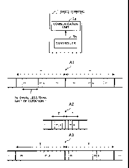
FIG. 1 explains a radio terminal according to a
first embodiment. As illustrated in FIG. 1, a radio
terminal 1 has a communication unit la and a controller lb.
CA 02862789 2014-07-08
-8-
Arrows Al to A3 illustrated in FIG. 1 indicate timing of
measurement of a base station, not illustrated, and timing
of monitoring of a paging signal performed by the radio
terminal 1. In FIG. 1, m indicates timing of measurement
of a base station, not illustrated, and p indicates timing
of monitoring of a paging signal performed by the radio
terminal 1.
The communication unit la intermittently performs
measurement of a base station, not illustrated, and
monitoring of a paging signal within the duration of a
periodic duration T.
For example, T illustrated in FIG. 1 indicates DRX.
The communication unit la intermittently performs
measurement (m) of a base station and monitoring of a
paging signal (p) within a DRX cycle of the DRX.
The controller lb controls the communication unit
la so as to perform measurement, within the duration T,
with intervals intervals less than half of the duration T.
Further, it is also made possible to perform filtering of
sample values (specifically, values of RSRP and RSRQ) of
radio quality obtained by measurement where the sample
values are spaced by less than half of the duration T.
For example, as indicated by the arrow Al, the
controller lb controls the communication unit la so as to
perform measurement where the sample values are spaced by
less than half of the duration T. Specifically, the
controller lb controls the communication unit la so as to
CA 02862789 2014-07-08
-9-
perform measurement where the sample values are spaced by
less than half of the DRX cycle.
The arrow A2 indicates an example of the
conventional timing of measurement and monitoring of a
paging signal. As described previously, it is specified
that decision of whether or not to perform measurement and
cell selection is performed at least with intervals of the
DRX cycle. Here, in order to suppress the power
consumption of the radio terminal 1, the length (DRX
cycle) of the duration T is increased as indicated by the
arrow A3.
The arrow A3 indicates another example of the
conventional timing of measurement and monitoring of a
paging signal. Without violating the specification,
measurement is performed with intervals of half the DRX
cycle (DRX cycle / 2). Further, in the calculation of
measured values of measurement, sample values of the
measurement are averaged and the averaged values are
measurement result of the radio quality of each cell. By
performing measurement and calculation of measured values,
it is possible to maintain the accuracy of measurement
even if the length (DRX cycle) of the duration T increases.
However, the conventional interval of measurement
increases as the DRX cycle increases, and therefore, the
averaging interval of measurement increases and the
accuracy of measurement deteriorates.
In contrast to this, as described above, the
CA 02862789 2014-07-08
-10-
controller lb controls the communication unit la so as to
perform measurement with intervals less than half of the
length of the duration T. Further, also in the filtering
of sample values (specifically, values of RSRP and RSRQ)
of the radio quality obtained by measurement, it is made
possible to perform filtering where the sample values are
spaced by less than half of the length. Due to this, the
radio terminal I may shorten the averaging interval of
measurement as well as suppressing power consumption, and
may suppress deterioration in measurement.
As described above, the communication unit la of
the radio terminal 1 performs measurement of the base
station and monitoring of a paging signal within the
duration of the periodic duration T. Then, the controller
lb controls the communication unit la so as to perform
measurement with intervals less than half of the length of
the duration T within the duration T. Due to this, the
radio terminal 1 may prevent the interval of measurement
from increasing and may suppress deterioration in
measurement even if the length of the duration T is
increased in order to suppress power consumption.
(Second embodiment)
Next, a second embodiment is explained in detail
with reference to drawings.
FIG. 2 illustrates a radio communication system
according to the second embodiment. FIG. 2 illustrates a
base station 11 and a radio terminal 12. The base station
=
CA 02862789 2014-07-08
=
-11-
11 and the radio terminal 12 perform radio communication
by the LTE-A or LTE communication system.
The radio terminal 12 is built in a device, such
as a gas meter and an electricity meter. The radio
terminal 12 transmits information such as an anomaly and a
usage fee detected by the device, for example, a gas meter
and an electricity meter, to the base station 11. The
information transmitted to the base station 11 is
transmitted to, for example, a gas company or an
electricity company.
The device as described above has communication
characteristics different from those of a mobile telephone
etc. For example, the device does not move and the amount
of communication is small. Consequently, it is thought
that the device is in the idle mode in most of time and
rarely enters the connected mode.
In the case where the device is installed in a
condominium etc., the base station 11 may be, for example,
a home eNB (evolved Node B). Further, the device may be
built in a sensor or a health meter for managing human
health condition, not limited to the above-described meter.
FIG. 3 is a function block diagram of a radio
terminal. As illustrated in FIG. 3, the radio terminal 12
has a communication unit 21 and a controller 22. The
controller 22 has a radio controller 22a, a control plane
layer controller 22b, and an application layer controller
22c.
CA 02862789 2014-07-08
-12-
The communication unit 21 performs control of
radio communication. For example, the communication unit
21 performs base band (BB) processing and radio frequency
(RF) processing of a signal transmitted to and received
from the base station 11. Further,
the power of the
communication unit 21 is turned on and off by the control
of the radio controller 22a of the controller 22.
The radio controller 22a controls the BB
processing and the RF processing of the communication unit
21. Further, the radio controller 22a performs turning on
and off control of the power of the communication unit 21.
The control plane layer controller 22b performs
control of an RRC (Radio Resource Control) layer and an
NAS layer.
The application layer controller 22c performs
control of an application layer.
The communication unit 21 corresponds to, for
example, the communication unit la in FIG. 1. The radio
controller 22a and the control plane layer controller 22b
correspond to, for example, the controller lb in FIG. 1.
FIG. 4 illustrates a hardware configuration
example of a radio terminal. As illustrated in FIG. 4, the
radio terminal 12 has a processor 31, a main memory 32, a
ROM (Read Only Memory) 33, a storage 34, a communication
interface 35, an input and output device 36, a display 37,
and a bus 38.
To the processor 31, the maim memory 32, the ROM
CA 02862789 2014-07-08
-13-
33, the storage 34, the communication interface 35, the
input and output device 36, and the display 37 are
connected via the bus 38. The whole of the radio terminal
12 is controlled by the processor 31. The processor 31 is,
for example, a CPU (Central Processing Unit) or a DSP
(Digital Signal Processor).
In the main memory 32, data and programs used in
various kinds of processing of the processor 31 are
temporarily stored. In the ROM 33, static information,
such as a protocol to specify the operation of the radio
terminal 12, is stored. For example, in the ROM 33,
information for the processor 31 to perform data plane
processing, control plane processing,
scheduling
processing, or the like is stored. In the storage 34, data
and programs used in various kinds of processing of the
processor 31 are stored. The communication interface 35
performs radio communication with the base station 11. For
example, the communication interface 35 converts a base
band signal into a radio frequency and outputs the radio
frequency to an antenna, not illustrated. Further, the
communication interface 35 frequency-converts a radio
signal received by an antenna, not illustrated, into a
base band signal.
The input and output device 36 is, for example, a
key, a speaker, or a microphone. For example, the key
receives a character or a numeral input by a user. The
speaker, for example, converts a voice signal received
CA 02862789 2014-07-08
-14-
from the base station 11 into voice and outputs the voice.
The microphone converts voice of a user into an electric
signal. The display 37 is, for example, an LCD (Liquid
Crystal Display). The display 37 displays, for example,
data received from the base station 11.
The function of the communication unit 21 in FIG.
3 is implemented by, for example, the communication
interface 35. The function of the controller 22 is
implemented by, for example, the processor 31.
FIG. 5 is a function block diagram of a base
station. As illustrated in FIG. 5, the base station 11 has
a communication unit 41 and a controller 42. The
controller 42 has a radio controller 42a and a control
plane layer controller 42b.
The communication unit 41 performs control of
radio communication. For example, the communication unit
41 performs BB processing and RF processing of a signal
transmitted to and received from the radio terminal 12.
The radio controller 42a controls BB processing
and RF processing of the communication unit 41.
The control plane layer controller 42b performs
control of the RRC layer and the NAS layer.
FIG. 6 illustrates a hardware configuration
example of a base station. As illustrated in FIG. 6, the
base station 11 has a processor 51, a main memory 52, a
ROM 53, a storage 54, a communication interface 55, and a
bus 56.
CA 02862789 2014-07-08
-15-
To the processor 51, the main memory 52, the ROM
53, the storage 54, and the communication interface 55 are
connected via the bus 56. The whole of the base station 11
is controlled by the processor 51. The processor 51 is,
for example, a CPU or a DSP.
In the main memory 52, data and programs used in
various kinds of processing of the processor 51 are
temporarily stored. In the ROM 53, static information,
such as a protocol to specify the operation of the base
station 11, is stored. For example, in the ROM 53,
information for the processor 51 to perform data plane
processing, control plane processing, scheduling
processing, or the like is stored. In the storage 54, data
and programs used in various kinds of processing of the
processor 51 are stored. The communication interface 55
performs radio communication with the radio terminal 12.
For example, the communication interface 55 converts a
base band signal into a radio frequency and outputs the
radio frequency to an antenna, not illustrated. Further,
the communication interface 55 frequency-converts a radio
signal received by an antenna, not illustrated, into a
base band signal. Furthermore, the communication interface
55 performs wired communication with a high-level
apparatus, such as an S-GW (Serving-Gateway).
FIG. 7 is part 1 of a timing chart of a radio
terminal. In FIG. 7, m indicates timing of measurement of
the radio terminal 12. Further, p indicates timing of
CA 02862789 2014-07-08
-16-
monitoring of a paging signal of the radio terminal 12.
In the example in FIG. 7, the timings of m and p
are different between before and after an event detected
by the application layer. An event occurs by, for example,
a charge report of an electricity meter or the like and an
anomaly report.
The radio terminal 12 uses a long DRX cycle longer
than the normal DRX cycle in order to, for example, reduce
power consumption.
Here, the measured value of the conventional
measurement is calculated by averaging samples of
measurement having at least an interval of "DRX cycle / 2".
Therefore, the interval of measurement increases, for
example, as indicated by the arrow A3 in FIG. 1 and the
measurement accuracy of measurement deteriorates.
In contrast to this, in the radio terminal 12,
measurement is performed at least once within the DRX
duration as conventionally. Consequently, it is possible
to perform measurement a plurality of times within the DRX
duration. However, a
measured value is calculated by
filtering a sample value of measurement wherein the sample
values are spaced by 'long DRX cycle / n' (n > 2).
Consequently, the radio terminal 12 performs measurement
with intervals of 'X' illustrated in FIG. 7.
The radio terminal 12 calculates a measured value
of measurement by, for example, averaging two measurements.
For example, the radio terminal 12 calculates a measured
CA 02862789 2014-07-08
-17-
value using sample values of two measurements of m on the
left side and of m on the right side in the long DRX cycle
before an event occurs illustrated in FIG. 7. Further, the
radio terminal 12 calculates a measured value using sample
values of measurements of the first m and the second m
from the left in the long DRX cycle after the occurrence
of the event. Further, the radio terminal 12 calculates a
measured value using sample values of measurements of the
third m and the fourth m from the left.
After the occurrence of the event, the number of
times of measurement within the long DRX cycle has
increased compared to that before the occurrence of the
event. For example, in FIG. 7, before the occurrence of
the event, the number of times of measurement is two, but
after the occurrence of the event, the number of times is
four. The reason for this is that camping on an
appropriate cell and appropriate notification of event
information to the base station are enabled by increasing
the number of times of measurement to improve the accuracy
of evaluation of measurement. When determining that it is
not possible to connect to the previous cell by the
measurement after the occurrence of the event, the radio
terminal 12 performs cell selection to attempt detection
of a new cell. Further, after transmitting UL data for the
event, the radio terminal 12 returns to the operation
before the occurrence of the event.
FIG. 8 is part 2 of the timing chart of the radio
CA 02862789 2014-07-08
-18-
terminal. In the timing chart in FIG. 8, the interval of
measurement after the occurrence of an event is short,
i.e., an interval Y, with respect to the timing chart in
FIG. 7. In other words, in FIG. 8, the frequency of
measurement is increased compared to that in FIG. 7. Due
to this, the power consumption of the radio terminal 12
increases compared to that in FIG. 7, but the accuracy of
measurement improves because the interval at which each
sample is averaged is shortened in calculation of a
measured value of measurement.
However, this does not mean that the shorter the
averaging interval, the better the measurement accuracy in
calculation of a measured value of measurement. If the
averaging interval is too short, there is a possibility
that an evaluation is made only in the instant of
excellent radio propagation condition or conversely, a
possibility that an evaluation is made only in the instant
of poor radio propagation condition. Therefore, it is
recommended to set the interval between each sample with
keeping some interval. For example, in FIG. 7, the
interval of filtering of measurement is set to 'X / 2' and
in FIG. 8, the interval of filtering of measurement is set
to 'Y / 2'.
Note that, the radio terminal 12 may resume the
usual measurement interval after the occurrence of the
event. For
example, the radio terminal 12 may perform
measurement with intervals of 'DRX cycle / 2' after the
CA 02862789 2014-07-08
-19-
occurrence of the event.
Acquisition of n that determines the interval of
measurement is explained. For example, n is notified from
the base station 11 by broadcast information.
Specifically, after the power is turned on, the
radio terminal 12 makes an initial cell search and camps
on a cell of good radio quality (suitable cell). At this
time, the radio terminal 12 performs an NAS Attach
procedure. When camping on a cell, the radio terminal 12
acquires the broadcast information of the cell from the
base station 11 and acquires n from the acquired broadcast
information. Due to this, the radio terminal 12 may
calculate the interval of measurement.
As illustrated in FIG. 8, when the interval of
measurement is changed between before and after the
occurrence of the event, the radio terminal 12 may notify
the base station 11 that an event has occurred and the
base station 11 may notify the radio terminal 12 of new n.
The base station 11 may also change n in accordance with,
for example, the type of the event (e.g., whether or not
the event is an emergency event).
Further, n may be determined in advance or may be
calculated from the device ID. For example, the device ID
is indicated by a value of 12 bits. The radio terminal 12
may divide the device ID of the radio terminal 12 by, for
example, an appropriate value, such as 4,000, and may set
the remainder to n.
CA 02862789 2014-07-08
-20-
The base station 11 may also notify the radio
terminal 12 of the number of times of measurement within
the long DRX cycle by broadcast information. Further, the
base station 11 may notify the number of times of
measurement within the long DRX cycle when receiving event
notification from the radio terminal 12.
FIG. 9 is a flowchart of a radio terminal.
(Step S1) The power of the radio terminal 12 is
turned on.
(Step S2) The control plane layer controller 22b
receives broadcast information from the base station 11.
In other words, the control plane layer controller 22b
receives 'n' which is used to calculate the interval of
measurement.
(Step S3) The control plane layer controller 22b
performs the NAS Attach procedure.
(Step S4) The control plane layer controller 22b
calculates the interval of measurement from the received
'n'. The radio controller 22a turns on and off the
communication unit 21 so as to perform measurement with
intervals calculated by the control plane layer controller
22b. The control plane layer controller 22b averages the
measured measurements to evaluate the quality thereof.
The control plane layer controller 22b performs
monitoring of paging with, for example, timing that
satisfies the following expression.
SFN mod T = (T div N) * (UE-ID mod N)
CA 02862789 2014-07-08
-21-
SFN is a system frame number. T is a DRX cycle
(long DRX cycle). UE-ID is an ID of the radio terminal. N
is a value determined by the DRX cycle.
(Step S5) The application layer controller 22c
stands by for an event.
(Step S6) The application layer controller 22c
determines whether or not an event has occurred. In the
case where an event has occurred, the application layer
controller 22c proceeds to step S7. In the case where no
event has occurred, the application layer controller 22c
proceeds to step S5.
(Step S7) The control plane layer controller 22b
and the radio controller 22a perform measurement with new
settings and make an evaluation of the quality thereof.
For example, the control plane layer controller 22b
performs measurement with new settings as explained in FIG.
8. The control plane layer controller 22b may perform
measurement as illustrated in FIG. 7.
FIG. 10 is a flowchart of a base station.
(Step S11) The control plane layer controller 42b
notifies the radio terminal 12 of broadcast information
via the radio controller 42a. The broadcast information
includes 'n' which is used to calculate the interval of
measurement.
(Step S12) The control plane layer controller 42b
performs the NAS Attach procedure.
(Step S13) The control plane layer controller 42b
CA 02862789 2014-07-08
-22-
stands by for an event report from the radio terminal 12.
(Step S14) The control plane layer controller 42b
determines whether or not the event report from the radio
terminal 12 is received. In the case where the event
report from the radio terminal 12 is received, the control
plane layer controller 42b proceeds to step S15. In the
case where the event report from the radio terminal 12 is
not received, the control plane layer controller 42b
proceeds to step S13.
(Step S15) The control plane layer controller 42b
notifies the radio terminal 12 of new 'n'.
As described above, the control plane layer
controller 22b and the radio controller 22a control the
communication unit 21 so as to perform filtering of
measurement, within the long DRX cycle, with intervals
less than half of the length of the long DRX cycle. Due to
this, the radio terminal 12 may suppress an increase in
the interval of measurement and may suppress deterioration
in the accuracy of measurement even if the long DRX cycle
is adopted in order to suppress power consumption.
Further, the control plane layer controller 22b
and the radio controller 22a, after the occurrence of the
event, increase the number of times of measurement within
the long DRX cycle compared to that before the event. Due
to this, the radio terminal 12 may improve the quality of
measurement.
Further, the control plane layer controller 22b
CA 02862789 2014-07-08
-23-
and the radio controller 22a, after the occurrence of the
event, reduce the interval of measurement compared to that
before the event. Due to this, the radio terminal 12 may
improve the quality of measurement
(Third embodiment)
Next, a third embodiment is explained in detail
with reference to drawings. In the third embodiment,
masking is performed on the conventional DRX to provide a
duration in which the DRX is not performed and the DRX is
performed periodically. Although the conventional DRX may
be performed in the duration in which the DRX is performed,
in order to improve the quality of measurement, it may
also be possible to perform measurement a plurality of
times within the DRX cycle and to perform filtering of
measurement with intervals less than half of the length of
the DRX cycle.
Note that, the radio communication system
according to the third embodiment is the same as that in
FIG. 2. The block of the radio terminal 12 is the same as
that in FIG. 3, but the function of the control plane
layer controller 22b is different. The hardware
configuration of the radio terminal 12 is the same as that
in FIG. 4. The block of the base station 11 is the same as
that in FIG. 5, but the function of the control plane
layer controller 42b is different. The hardware
configuration of the base station 11 is the same as that
in FIG. 6.
CA 02862789 2014-07-08
-24-
FIG. 11 is a timing chart of a radio terminal
according to the third embodiment. In FIG. 11, the long
DRX cycle in FIG. 7 is replaced with the DRX cycle. Other
portions in FIG. 11 are the same as those in FIG. 7, and
therefore, explanation thereof is omitted.
The radio terminal 12 acts so that, before an
event occurs, the DRX cycle is masked in which measurement
is not performed and the DRX is performed periodically
(thick line in FIG. 11). The radio terminal 12 performs
measurement and monitoring of a paging signal within the
DRX cycle not masked.
In the section not masked, the radio terminal 12
performs measurement at intervals of 'DRX cycle / n' (n >
2) as illustrated in FIG. 11. Consequently, the radio
terminal 12 performs filtering of measurement at intervals
of 'X' illustrated in FIG. 11.
After the occurrence of the event, the radio
terminal 12 does not mask the DRX cycle. In other words,
the radio terminal 12 performs measurement and monitoring
of a paging signal in each DRX cycle as illustrated in FIG.
11.
FIG. 12 explains a mask pattern of the DRX. The
control plane layer controller 22b of the radio terminal
12 releases the mask of the DRX in synchronization with
the BCCH (Broadcasting Control Channel) modification
period, which is the period to check a change of the
broadcast information.
CA 02862789 2014-07-08
-25-
Double-headed arrows All, Al2 illustrated in FIG.
12 indicate the BCCH modification period. The control
plane layer controller 22b releases the mask of the DRX
with timing of dotted lines A13, A14 illustrated in FIG.
12. For example, the control plane layer controller 22b
controls the radio controller 22a so as to turn on the
communication unit 21 (so as to perform DRX) with the
timing of the dotted lines A13, A14.
The alternate long and short dash line illustrated
in FIG. 12 indicates the period of time during which the
mask of the DRX cycle is released (period of time during
which DRX is performed). The rectangle and the rectangle
with slashes illustrated in FIG. 12 indicate the broadcast
information (SIB: System Information Block) notified to
the radio terminal 12 from the base station 11.
The control plane layer controller 22b monitors
SIB1 (rectangle with slashes rising toward the right in
FIG. 12) or a paging signal to check whether or not there
is a change in the broadcast information. The control
plane layer controller 22b turns on the communication unit
21 to monitor the SIB1 and paging signal. The
control
plane layer controller 22b performs measurement and
monitoring of a paging signal by utilizing this timing.
The rectangle with slashes falling toward the right
indicates the SIB whose information has been changed.
The period of time during which the mask is
released may be notified by, for example, broadcast
CA 02862789 2014-07-08
-26-
information, or may be determined in advance. Further, the
period of time may be calculated from the device ID of the
radio terminal 12. Furthermore, the radio terminal 12 may
freely release the mask by implementation thereof.
In the above, it is described that the mask
pattern synchronizes with the BCCH modification period,
and now a setting example of another mask pattern is
explained.
Example 1: The base station 11 broadcasts a
masking pattern by broadcast information. For example, the
base station 11 broadcasts within which DRX cycle to
perform the DRX by broadcast information. The control
plane layer controller 22b of the radio terminal 12
releases the mask within the DRX cycle included in the
received broadcast information and performs measurement
and monitoring of a paging signal. The period of time
during which the mask is released may be broadcasted by,
for example, broadcast information, or may be determined
in advance. Further, the period of time may be calculated
from the device ID of the radio terminal 12.
Example 2: A masking pattern is notified by a
paging signal. For example, when the radio terminal 12
camps on, the base station 11 notifies a masking pattern
of the DRX by a paging signal.
Example 3: When the radio terminal 12 camps on,
the location is registered in an MME (Mobility Management
Entity). The location registration is performed in the NAS
CA 02862789 2014-07-08
-27-
layer and the NAS Attach procedure is performed. The radio
terminal 12 receives a masking pattern by an NAS Attach
Accept of an NAS message transmitted and received by the
NAS Attach procedure.
Example 4: Each time the DRX is masked N times,
the masking of the DRX is released. N may be notified by
broadcast information from the base station 11 or may be
determined in advance by the base station 11 and the radio
terminal 12. Further, N may be calculated from the device
ID of the radio terminal 12.
Example 5: Based on an IMSI (International Mobile
Subscriber Identity), which is an identifier of a radio
terminal, a radio frame in which the mask of the DRX is
released is determined. For example, the mask of the DRX
is released in the radio frame in which the SFN mod DRX
cycle and func (IMSI) become equal to each other. The func
( ) is an appropriate function and for example, a function
that outputs a value by the IMSI.
FIG. 13 is a flowchart of a radio terminal.
(Step S21) The power of the radio terminal 12 is
turned on.
(Step S22) The control plane layer controller 22b
receives broadcast information from the base station 11.
(Step S23) The control plane layer controller 22b
performs the NAS Attach procedure.
(Step S24) The control plane layer controller 22b
receives a mask pattern of the DRX by performing the NAS
CA 02862789 2014-07-08
-28-
Attach procedure. The flowchart in FIG. 13 illustrates a
processing example in the case of Example 3 described
above.
(Step S25) The control plane layer controller 22b
controls the radio controller 22a so as to perform the DRX
with the received mask pattern. The radio controller 22a
turns on and off the communication unit 21 in accordance
with the control of the control plane layer controller 22b
so that measurement and monitoring of a paging signal are
performed. The control plane layer controller 22b averages
measured measurements to evaluate the quality thereof.
(Step S26) The application layer controller 22c
stands by for an event.
(Step S27) The application layer controller 22c
determines whether or not the event has occurred. In the
case where the event has occurred, the application layer
controller 22c proceeds to step S28. In the case where no
event has occurred, the application layer controller 22c
proceeds to step S26.
(Step S28) The control plane layer controller 22b
releases all the masks. For example, the control plane
layer controller 22b controls the radio controller 22a so
that measurement and monitoring of a paging signal are
performed in each DRX cycle as illustrated after the
occurrence of the event in FIG. 11.
FIG. 14 is a flowchart of a base station.
(Step S31) The control plane layer controller 42b
CA 02862789 2014-07-08
29403-12
-29-
notifies the radio terminal 12 of broadcast information via the
radio controller 42a.
(Step S32) The control plane layer controller 42b
performs the NAS Attach procedure.
(Step S33) The control plane layer controller 42b
transmits a mask pattern of the DRX by the NAS Attach
procedure. The flowchart in FIG. 14 illustrates a processing
example in the case of Example 3 described above.
(Step S34) The control plane layer controller 42b
stands by for an event report from the radio terminal 12.
(Step S35) The control plane layer controller 42b
determines whether or not the event report from the radio
terminal 12 is received. In the case where the event report
from the radio terminal 12 is received, the control plane layer
controller 42b ends the processing. In the case where the
event report from the radio terminal 12 is not received, the
control plane layer controller 42b proceeds to step S34.
As described above, the control plane layer
controller 42b acts so that a duration during which the DRX is
not performed is set and the DRX is performed periodically.
Then, the control plane layer controller 42b and the radio
controller 42a perform filtering of measurement at intervals
less than half the cycle length of the DRX cycle within the DRX
cycle of the DRX performed periodically. Due to this, the
radio terminal 12 may
CA 02862789 2014-07-08
-30-
suppress an increase in the interval of measurement and
may suppress deterioration in measurement within the DRX
cycle of the DRX performed periodically in order to
suppress power consumption.
(Fourth embodiment)
Next, a fourth embodiment is explained in detail
with reference to drawings. In the fourth embodiment, the
base station specifies the DRX to be performed next.
The radio communication system according to the
fourth embodiment is the same as that in FIG. 2. The block
of the radio terminal 12 is the same as that in FIG. 3,
but the function of the control plane layer controller 22b
is different. The hardware configuration of the radio
terminal 12 is the same as that in FIG. 4. The block of
the base station 11 is the same as that in FIG. 5, but the
function of the control plane layer controller 42b is
different. The hardware configuration of the base station
11 is the same as that in FIG. 6.
FIG. 15 is a timing chart of a radio terminal
according to the fourth embodiment. In FIG. 15, the DRX to
be performed next is specified by a paging signal, which
is different from FIG. 11. Other portions in FIG. 15 are
the same as those in FIG. 11, and therefore, explanation
thereof is omitted.
When camping on a cell of the base station 11, the
control plane layer controller 22b of the radio terminal
12 performs measurement and monitoring of a paging signal.
CA 02862789 2014-07-08
-31-
The base station 11 specifies within which DRX the radio
terminal 12 next performs measurement and monitoring of a
paging signal by a paging signal. The control plane layer
controller 22b performs measurement and monitoring of a
paging signal within the specified DRX.
The period of time during which the DRX is
performed may be specified by the paging signal or
notified by broadcast information. Further, the period of
time may be determined in advance or may be calculated
from the device ID of the radio terminal 12. Furthermore,
the period of time may be determined by implementation of
the radio terminal. For example, the base station 11
specifies the start of the DRX by broadcast information
and the period of time of the DRX is determined by
implementation of the radio terminal 12.
The base station 11 may specify to perform the DRX
by the NAS. For example, when the radio terminal 12 camps
on, the location is registered in the MME. The location
registration is performed in the NAS layer and the NAS
Attach procedure is performed. The base station 11
specifies the DRX to be performed next by the NAS Attach
Accept of the NAS message transmitted and received by the
NAS Attach procedure. The period of time during which the
DRX is performed may be notified by the NAS Attach Accept
or notified by broadcast information. Further, the period
of time may be determined in advance or may be determined
by the device ID of the radio terminal 12.
CA 02862789 2014-07-08
-32-
FIG. 16 is a flowchart of a radio terminal.
(Step S41) The power of the radio terminal 12 is
turned on.
(Step S42) The control plane layer controller 22b
receives broadcast information from the base station 11.
(Step S43) The control plane layer controller 22b
performs the NAS Attach procedure.
(Step S44) The control plane layer controller 22b
receives the DRX to be performed next by a paging signal
or by performing the NAS Attach procedure.
(Step S45) The control plane layer controller 22b
controls the radio controller 22a so as to perform the DRX
specified by the base station 11 (step S44). The control
plane layer controller 22b performs measurement by the DRX
and makes an evaluation thereof.
(Step S46) The application layer controller 22c
stands by for an event.
(Step S47) The application layer controller 22c
determines whether or not the event has occurred. In the
case where the event has occurred, the application layer
controller 22c proceeds to step S48. In the case where no
event has occurred, the application layer controller 22c
proceeds to step S46.
(Step S48) The control plane layer controller 22b
performs all the DRXs. For example, as illustrated after
the occurrence of the event in FIG. 15, the control plane
layer controller 22b controls the radio controller 22a so
CA 02862789 2014-07-08
-33-
that measurement and monitoring of a paging signal are
performed in each DRX cycle.
FIG. 17 is a flowchart of a base station.
(Step S51) The control plane layer controller 42b
notifies the radio terminal 12 of broadcast information
via the radio controller 42a.
(Step S52) The control plane layer controller 42b
performs the NAS Attach procedure.
(Step S53) The control plane layer controller 42b
transmits the DRX to be performed next by a paging signal
or by performing the NAS Attach procedure.
(Step S54) The control plane layer controller 42b
stands by for an event report from the radio terminal 12.
(Step S55) The control plane layer controller 42b
determines whether or not to have received an event report
from the radio terminal 12. In the case of having received
an event report from the radio terminal 12, the control
plane layer controller 42b ends the processing. In the
case of not having received an event report from the radio
terminal 12, the control plane layer controller 42b
proceeds to step S54.
As described above, the control plane layer
controller 42b receives the DRX to be performed next by a
paging signal or the NAS. Then, the control plane layer
controller 42b and the radio controller 42a perform
filtering of measurement at intervals less than half the
cycle length of the DRX cycle within the DRX cycle of the
CA 02862789 2014-07-08
-34-
DRX to be performed next. Due to this, the radio terminal
12 may suppress deterioration in measurement as well as
suppressing power consumption.
(Fifth embodiment)
Next, a fifth embodiment is explained in detail
with reference to drawings. In the fifth embodiment, two
DRX cycles are set and measurement and monitoring of a
paging signal are performed.
The radio communication system according to the
fifth embodiment is the same as that in FIG. 2. The block
of the radio terminal 12 is the same as that in FIG. 3,
but the function of the control plane layer controller 22b
is different. The hardware configuration of the radio
terminal 12 is the same as that in FIG. 4. The block of
the base station 11 is the same as that in FIG. 5, but the
function of the control plane layer controller 42b is
different. The hardware configuration of the base station
11 is the same as that in FIG. 6.
FIG. 18 is a timing chart of a radio terminal
according to the fifth embodiment. FIG. 18 illustrates a
short DRX cycle and a long DRX cycle whose period of time
is longer than that of the short DRX cycle. The short DRX
cycle is, for example, the conventional DRX cycle and the
long DRX cycle is made longer in cycle than the short DRX
cycle in order to suppress power consumption of the radio
terminal 12.
The radio terminal 12 performs the DRX in the
CA 0627139 213107-138
29403-12
-35-
short DRX cycle, for example, for a predetermined period of
time and after that, performs the DRX in the long DRX cycle for
a predetermined period of time. Then, the radio terminal 12
repeats these operations. The period of time during which the
DRX in the short DRX cycle is performed and the period of time
during which the DRX in the long DRX cycle is performed are
notified by broadcast information, for example.
If the DRX cycle is lengthened simply, the interval
of time during which measurement is performed is also
lengthened, and therefore, the control plane layer controller
22b of the radio terminal 12 performs measurement, within the
long DRX, at least once with conventional intervals of the DRX.
Consequently, it is possible to perform measurement a plurality
of times within a DRX duration. However, measurement is
performed with intervals of 'long DRX cycle / n' (n > 2).
Consequently, the radio terminal 12 performs control so as to
perform filtering of measurement at least with an interval of
'X' as illustrated in FIG. 18. The control plane layer
controller 22b may perform measurement as conventionally in the
short DRX cycle, but in order to improve measurement accuracy,
performs filtering of measurement at least with an interval of
'short DRX cycle / 2'.
The radio terminal 12 averages two measurements to
calculate a measured value of measurement. For example, the
radio terminal 12 performs filtering of two sample values of m
on the left side and of m on the right side in the long DRX
cycle illustrated in FIG. 18.
As a modification example, if the DRX cycle is
lengthened simply, it is obvious that the interval of time
CA 02862789 2014-07-08
29403-12
-36-
during which measurement is performed is lengthened, and
therefore, there is also a method in which measurement and
monitoring of a paging signal are not at all performed in the
long DRX cycle.
In the above, the period of time during which the DRX
in the short DRX cycle is performed and the period of time
during which the DRX in the long DRX cycle is performed are
notified by broadcast information, and here, another example is
explained.
Example 1: When the radio terminal 12 camps on, the
base station 11 notifies a period of time during which the DRX
is performed by a paging signal.
Example 2: When the radio terminal 12 camps on, the
location is registered in the MME. The location registration
is performed in the NAS layer and the NAS Attach procedure is
performed. The radio terminal 12 receives a period of time
during which the DRX is performed by the NAS Attach Accept of
the NAS message transmitted and received by the NAS Attach
procedure.
Example 3: The control plane layer controller 22b
performs the DRX in the short DRX cycle N times, and then,
performs the DRX in the long DRX cycle M times. The values
CA 02862789 2014-07-08
-37-
of N and M may be notified by broadcast information or
values determined in advance may be used. Further, the
control plane layer controller 22b may calculate the
values of N and M from the device ID of the radio terminal
12.
Example 4: The control plane layer controller 22b
switches the DRX cycles in conjunction with the BCCH
modification period explained in FIG. 12. For example, the
control plane layer controller 22b performs the DRX in the
short DRX cycle every N modification boundaries (the
dotted lines A13, A14 in FIG. 12). The period of time
during which the DRX in the short DRX cycle is performed
may be notified by, for example, broadcast information or
a value determined in advance may be used. Further, the
control plane layer controller 22b may calculate a period
of time during which the DRX in the short DRX cycle is
performed from the device ID of the radio terminal 12.
Example 5: The control plane layer controller 22b
starts the DRX in the short DRX cycle in the radio frame
in which the SFN mod DRX cycle and the func (IMSI) become
equal to each other. The control plane layer controller
22b performs the DRX in the short DRX cycle in N
successive radio frames. N may be notified by, for example,
broadcast information or a value determined in advance may
be used. Further, the control plane layer controller 22b
may calculate N from the device ID of the radio terminal
12. When ending the DRX in the short DRX cycle, the
CA 02862789 2014-07-08
-38-
control plane layer controller 22b performs the DRX in the
long DRX cycle.
FIG. 19 is a flowchart of a radio terminal.
(Step S61) The power of the radio terminal 12 is
turned on.
(Step S62) The control plane layer controller 22b
receives broadcast information from the base station 11.
(Step S63) The control plane layer controller 22b
performs the NAS Attach procedure.
(Step S64) The control plane layer controller 22b
acquires a period of time during which the DRX in the
short DRX cycle is performed and a period of time during
which the DRX in the long DRX cycle is performed by the
NAS Attach Accept, for example. The control plane layer
controller 22b may also acquire a period of time during
which the DRX in the short DRX cycle is performed and a
period of time during which the DRX in the long DRX cycle
is performed from broadcast information.
(Step S65) The control plane layer controller 22b
controls the radio controller 22a so as to perform the DRX
in the short DRX cycle and in the long DRX cycle specified
by the base station 11 (step S64). The control plane layer
controller 22b performs measurement by the DRX and makes
an evaluation thereof.
FIG. 20 is a flowchart of a base station.
(Step S71) The control plane layer controller 42b
notifies the radio terminal 12 of broadcast information
CA 02862789 2014-07-08
-39-
via the radio controller 42a.
(Step S72) The control plane layer controller 42b
performs the NAS Attach procedure.
(Step S73) The control plane layer controller 42b
transmits the period of time during which the DRX in the
short DRX cycle and the DRX in the long DRX cycle are
performed by broadcast information or by performing the
NAS Attach procedure, for example.
As described above, the control plane layer
controller 42b performs the DRX in the short DRX cycle and
in the long DRX cycle. Due to this, the radio terminal 12
may improve accuracy of measurement by the short DRX cycle
as well as suppressing power consumption by the long DRX
cycle.
(Sixth embodiment)
Next, a sixth embodiment is explained in detail
with reference to drawings. In the sixth embodiment, after
the power of the radio terminal 12 is turned on, the NAS
Attach procedure and the NAS Detach procedure are
performed. After that, the radio terminal 12 turns off the
power of the communication unit 21. After that, if an
event is detected in the application layer, the radio
terminal 12 performs measurement and monitoring of a
paging signal by the DRX and for example, transmits
information of the event to the base station 11 by the UL.
The radio communication system according to the
six embodiment is the same as that in FIG. 2. The block of
CA 02862789 2014-07-08
-40-
the radio terminal 12 is the same as that in FIG. 3, but
the function of the control plane layer controller 22b is
different. The hardware configuration of the radio
terminal 12 is the same as that in FIG. 4. The block of
the base station 11 is the same as that in FIG. 5, but the
function of the control plane layer controller 42b is
different. The hardware configuration of the base station
11 is the same as that in FIG. 6.
FIG. 21 is a timing chart of a radio terminal
according to the sixth embodiment. An arrow A21 in FIG. 21
indicates performing of the NAS Attach procedure and an
arrow A22 indicates performing of the NAS Detach procedure.
When the power is turned on, the radio terminal 12 makes a
cell search and registers the location by performing the
NAS Attach procedure as indicated by the arrow A21. Then,
the radio terminal 12 turns off the power of the
communication unit 21 by performing the NAS Detach
procedure as indicated by the arrow A22.
When detecting an event having occurred in the
application layer, the application layer controller 22c of
the radio terminal 12 notifies the control plane layer
controller 22b of the detection. The control plane layer
controller 22b controls the radio controller 22a so as to
turn on the communication unit 21.
The control plane layer controller 22b registers
the location by performing the NAS Attach procedure as
indicated by an arrow A23. The control plane layer
CA 02862789 2014-07-08
-41-
controller 22b performs the DRX in the short DRX cycle to
perform measurement and monitoring of a paging signal.
The control plane layer controller 22b transmits
event information to the base station 11 as UL data and
performs the NAS Detach procedure as indicated by an arrow
A24. Then, the control plane layer controller 22b turns
off the power of the communication unit 21.
After that, when an event is detected by the
application layer controller 22c, the control plane layer
controller 22b performs the same operation as that
described above.
FIG. 22 explains the operations of the NAS Attach
procedure and the NAS Detach procedure.
(Step S81) The control plane layer controller 22b
of the radio terminal 12 transmits an NAS Attach Request
to the base station 11.
(Step S82) The control plane layer controller 42b
of the base station 11 transmits the NAS Attach Accept to
the radio terminal 12.
(Step S83) The control plane layer controller 22b
of the radio terminal 12 transmits an NAS Attach Complete
to the base station 11.
(Step S84) The control plane layer controller 22b
of the radio terminal 12 transmits an NAS Detach Request
to the base station 11.
(Step S85) The control plane layer controller 42b
of the base station 11 transmits the NAS Detach Accept to
CA 02862789 2014-07-08
-42-
the radio terminal 12.
FIG. 23 is a flowchart of a radio terminal.
(Step S91) The power of the radio terminal 12 is
turned on.
(Step S92) The control plane layer controller 22b
performs the NAS Attach procedure and the NAS Detach
procedure. For example, the control plane layer controller
22b performs what is indicated by the arrow A21 and what
is indicated by the arrow A22 illustrated in FIG. 21.
(Step S93) The application layer controller 22c
stands by for an event.
(Step S94) The application layer controller 22c
determines whether or not an event has occurred. In the
case where an event has occurred, the application layer
controller 22c proceeds to step S95. In the case where no
event has occurred, the application layer controller 22c
proceeds to step S93.
(Step S95) The radio controller 22a turns on the
communication unit 21 in accordance with the control of
the control plane layer controller 22b.
(Step S96) The control plane layer controller 22b
causes the DRX to be performed.
(Step S97) The control plane layer controller 22b
performs the NAS Attach procedure.
(Step S98) The communication unit 21 transmits
event information in the UL to the base station 11.
(Step S99) The control plane layer controller 22b
CA 02862789 2014-07-08
-43-
performs the NAS Detach procedure.
FIG. 24 is a flowchart of a base station.
(Step S101) The control plane layer controller 42b
performs the NAS Attach procedure.
(Step S102) The control plane layer controller 42b
communicates with the radio terminal 12 via the radio
controller 42a and the communication unit 41.
(Step S103) The control plane layer controller 42b
performs the NAS Detach procedure. The above-described
processing is the same before and after the event.
As described above, the control plane layer
controller 42b controls the radio controller 22a so as to
perform the DRX in conjunction with event detection by the
application layer controller 22c. Due to this, the radio
terminal 12 may suppress power consumption before an event
occurs.
The above only illustrates the principles of the
invention. Further, it is possible for a person skilled in
the art to make various modifications and alterations and
the present invention is not limited to the accurate
configurations and applied examples illustrated and
explained as above and all corresponding modification
examples and equivalents thereof are regarded within the
scope of the present invention according to the attached
claims and equivalents thereof.
Reference Signs List
CA 02862789 2014-07-08
-44-
1 radio terminal
la communication unit
lb controller