Note: Descriptions are shown in the official language in which they were submitted.
81781534
DEVICES AND METHODS FOR TREATING ACCIDENTAL BOWEL LEAKAGE
CROSS-REFERENCE TO RELATED APPLICATIONS
[0001] This application claims priority to U.S. Provisional Patent
Application
Serial No. 61/593,052, filed January 31,2012 and titled "ABL FLUSHABLE
WIPE/BODY
LINER", to U.S. Provisional Patent Application Serial No. 61/649,749, filed on
May 21, 2012
and titled"BODY LINER FORMAL LEAKAGE", to U.S. Design Patent Application No.
29/422,461, filed May 21, 2012 and titled "BODY LINER FOR ANAL LEAKAGE", and
to
U.S. Design Patent Application No. 29/437,530, filed November 16, 2012 and
titled "BODY
LINER FOR ANAL LEAKAGE':
FIELD
[0002] Described here are body liners and. methods for treating
fecal
incontinence.
BACKGROUND
[0003] Accidental bowel leakage (ABL), also known as fecal
incontinence., is a
widespread, debilitating condition, affecting millions worldwide. ABL is
typically characterized
by small amounts (typically about 1 nil or less) of viscoelastic bowel
discharge including feces
or otherwise-contaminated moisture, which may travel away from the anus to
soil the gluteal
cleft and potentially the sufferer's garment& As opposed to defecation (which
occurs when the
anus is opened by the anal sphincter muscles), the discharge associated with
ABL may ocCur
even when the sphincter muscles are clenched. ABL is often unpredictable, and
has a significant
impact on the quality of life for affected individuals. People at risk for ABL
include, but are not
limited to, mature persons with chronic bowel disturbances (e.g., dianfiea and
IBS), who smoke,
are obese, have neurological disorders (e.g, resulting from diabetes, MS, or
spine and/or rectal
injuries), or have undergone cholecystectomy, lower spine and/or rectal zone
surgeries, women
who have given birth, and men who have had prostrate treatment.
[0004] Current incontinence pads and devices do not provide an
adequate
solution for those suffering from ABL. Invasive approaches, including ostomy
collectors,
, .
CA 2863163 2019-04-15
CA 02863163 2014-07-29
WO 2013/116391 PCT/US2013/023928
valves, plugs, and injectable gels can be intrusive, carry health risks, and
may be excessive for
instances of mild or moderate bowel leakage, where relatively small amounts of
discharge (e.g.,
about 1 ml or less) is released. Traditional incontinence pads and diapers can
be bulky,
conspicuous, and embarrassing, and may not prevent fecal matter from exiting
the intergluteal
cleft. This may require additional cleanup, and may contribute to feelings of
uncleanliness.
Further, the bulk may make discreetly carrying replacements more difficult. A
lack of
satisfactory solutions may drive ABL sufferers to attempt makeshift solutions
(e.g., wads of
toilet paper placed in the intergluteal cleft, which are easily displaced
during movement), or to
avoid an active lifestyle altogether. Accordingly, it is desirable to provide
discreet, non-invasive
treatment devices for people suffering from ABL.
BRIEF SUMMARY
[00051 Described here are devices and methods for treating fecal
incontinence.
Generally, the devices described here comprise a body liner sized and
configured to be placed at
least partially within the intergluteal cleft. The body liner generally
comprises at least one body
liner layer and is configured to absorb fluid from a load of ABL. In some
variations, the body
liner has a body-facing surface and a rear surface opposite the body-facing
surface, wherein the
body liner is formed from a plurality of liner layers and comprises at least
one adhesive region
on the body-facing surface of the body liner. The plurality of liner layers
may comprise a top
sheet, a back sheet, and a core member, and each of the plurality of liner
layers may be liquid
absorbent. In some of these variations, the top sheet may form the body-facing
surface of the
body liner and the back sheet may form the rear surface of the body liner. The
body-facing
surface may have a higher coefficient of friction than a coefficient of
friction of the rear surface.
In other variations the body-facing surface may have a coefficient of friction
less than that of the
rear surface, or equal to that of the rear surface. In some variations, the
coefficient of friction of
the rear surface may be less than 0.15. In some of these variations, the
coefficient of friction of
the front surface is greater than 0.25.
[0006] In some variations when the body liner comprises a top sheet,
a back
sheet, and a core member, the core member may be positioned between the top
sheet and the
back sheet. The core member may be any suitable shape, such as, for example,
circular or oval.
The body liner may have any suitable shape, such as, for example, a butterfly
shape, a
rectangular shape, an oval shape, or the like. In some variations, the body
liner may have a
2
CA 02863163 2014-07-29
WO 2013/116391 PCT/US2013/023928
longitudinal axis, and the top sheet may have a shape comprising a first lobe
on a first side of the
longitudinal axis and a second lobe on a second side of the longitudinal axis.
In some of these
variations, the shape of the top sheet may further comprise a third lobe on
the first side of the
longitudinal axis and a fourth lobe on the second side of the longitudinal
axis. In some of these
variations, the back sheet may have a shape that is the same as the shape of
the top sheet.
[0007] In some variations where the body liner comprises a top sheet
and a back
sheet, the back sheet and the top sheet may be at least partially bonded
together. In some of
these variations, the back sheet and top sheet may be bonded together around a
periphery of the
top sheet. In some of these variations, the back sheet and top sheet may be
bonded together such
that at least 80 percent of the top sheet remains unbonded. In some of these
variations, the back
sheet and top sheet may be bonded together such that at least 90 percent of
the top sheet remains
unbonded. In some variations the body liner may be configured to be flushable.
In some of
these variations, at least 90 percent of the body liner may be formed from one
or more
biodegradable materials.
[0008] In variations where the body liner comprises a top sheet, the
top sheet may
be configured to move fluid within the top sheet at a first wicking rate in a
first direction, a
second wicking rate in a second direction, and a third wicking rate in a third
direction, wherein
first and second directions are within a plane of the body liner, the first
direction is perpendicular
to the second direction, and the third direction is perpendicular to the plane
of the body liner. In
some of these variations, the top sheet may be configured such that the third
wicking rate in the
top sheet is greater than the first and second wicking rates in the top sheet.
In some of these
variations, the top sheet may be configured such that the first wicking rate
in the top sheet is
greater than the second wicking rate in the top sheet. In some of these
variations, the body liner
has a longitudinal axis along which the body liner may be folded when placed
at least partially in
the intergluteal cleft, and the first direction may be parallel to the
longitudinal axis. In others of
these variations, the body liner has a longitudinal axis along which the body
liner is folded when
placed at least partially in the intergluteal cleft, and the second direction
may parallel to the
longitudinal axis.
[0009] In variations where the body liner comprises a back sheet, the
back sheet
may be configured to move fluid within the back sheet at a first wicking rate
in the first
direction, a second wicking rate in the second direction, and a third wicking
rate in the third
3
CA 02863163 2014-07-29
WO 2013/116391 PCT/US2013/023928
direction, wherein the third wicking rate in the back sheet may be greater
than the first wicking
rate in back sheet and greater than the second wicking rate in the back sheet.
In some of these
variations, the third wicking rate in the back sheet may be the same as the
third wicking rate in
the top sheet. In others of these variations, the first wicking rate in the
back sheet may be greater
than the second wicking rate in the back sheet. In some of these variations,
the first wicking rate
in the top sheet may be greater than the second wicking rate in the top sheet.
[0010] In other variations of the devices described here, the devices
may
comprise a body liner sized and configured to be placed at least partially
within the intergluteal
cleft and having a body-facing surface and a rear surface opposite the body-
facing surface,
wherein the body liner is formed from at least one liner layer, wherein the
body-facing surface
has a coefficient of friction and the rear surface has a coefficient of
friction. In some of these
variations, the coefficient of friction of the body-facing surface is greater
than the coefficient of
friction of the rear surface. In others of these variations, the coefficient
of friction of rear surface
may be greater than the coefficient of friction of the body-facing surface. In
yet other variations,
the body-facing surface and rear surface may have equal coefficient of
frictions. The body-
facing and rear facing surfaces may have any suitable coefficients of
friction. In some
variations, the coefficient of friction of the body-facing surface may be
greater than 0.25. In
some of these variations, the coefficient of friction of the body-facing
surface may be greater
than 0.3. In some variations, the coefficient of friction of the rear surface
may be less than 0.15.
In some variations, the coefficient of friction of the rear surface may be
less than 0.1. The body
liner may, in some variations, comprise at least one adhesive region on the
body-facing surface
of the body liner
[0011] When the body liner is formed from at least one liner layer,
one or more
portions of the body liner may be configured to be fluid absorbent. In some
variations, each liner
layer of the at least one liner layer may be fluid absorbent. In some
variations, the at least one
liner layer may comprise a top sheet and a core member, and one or both of the
top sheet and
core member may be fluid absorbent. In some of these variations, at least one
liner layer further
may comprise a back sheet, which in some variations may be positioned between
the top sheet
and the back sheet. The back sheet may also be fluid absorbent.
[0012] In some instances when the body liner is configured to absorb
fluid, the
body liner may be further configured to move fluid within the body liner at a
first wicking rate in
4
CA 02863163 2014-07-29
WO 2013/116391 PCT/US2013/023928
a first direction, a second wicking rate in a second direction, and a third
wicking rate in a third
direction, wherein the first and second directions are within a plane of the
body liner, the first
direction is perpendicular to the second direction, and the third direction is
perpendicular to the
plane of the body liner. In some of these variations, the third wicking rate
in the body liner may
be greater than the first wicking rate in the body liner and may be greater
than the second
wicking rate in the body liner. In some of these variations, the first wicking
rate in the body liner
may be greater than the second wicking rate in the body liner. In some of
these variations, the
body liner has a longitudinal axis along which the body liner may be folded
when placed at least
partially within the intergluteal cleft, and wherein the second direction is
parallel to the
longitudinal axis. In others of these variations, the body liner has a
longitudinal axis along
which the body liner may be folded when placed at least partially within the
intergluteal cleft,
wherein the first direction is parallel to the longitudinal axis. In some
variations, the first wicking
rate in the body liner may be greater than the second wicking rate in the body
liner.
[0013] As mentioned above, the body liner may have any suitable
shape. For
example, in some variations, the body liner has a longitudinal axis along
which the body liner
may be folded when placed at least partially within the intergluteal cleft,
and wherein the body
liner may have a shape comprising a first lobe on a first side of the
longitudinal axis and a
second lobe on a second side of the longitudinal axis. In some of these
variations, the shape of
the body liner may further comprise a third lobe on the first side of the
longitudinal axis and a
fourth lobe on the second side of the longitudinal axis. In some variations,
the rear surface of the
body liner may be configured to have a reduced coefficient of friction (e.g.,
may be polished,
may comprise one or more friction-reducing coatings, combinations thereof and
the like). In
other variations, the body-facing surface of the body liner may be configured
to enhance the
coefficient of friction of the body-facing surface (e.g., the body-facing
surface may be textured
or roughened, or the like). In some variations, the body liner may be
configured to be flushable.
In some variations, each liner layer of the at least one liner layer may be
formed from one or
more cellulosic materials.
[0014] In still other variations of the devices described here, the
devices may
comprise a body liner sized and configured to be placed at least partially
within the intergluteal
cleft, the body liner having a longitudinal axis along which the body may be
folded when placed
at least partially with the intergluteal cleft, a body-facing surface, and a
rear surface opposite the
CA 02863163 2014-07-29
WO 2013/116391 PCT/US2013/023928
body-facing surface, wherein the body liner is formed from at least one liner
layer, wherein the
body liner may be configured to move fluid within the body liner at a first
wicking rate in a first
direction, a second wicking rate in a second direction, and a third wicking
rate in a third
direction, wherein first and second directions are within a plane of the body
liner, the first
direction is perpendicular to the second direction, and the third direction is
perpendicular to the
plane of the body liner, and wherein the third wicking rate in the body liner
is greater than the
first wicking rate in the body liner and is greater than the second wicking
rate in the body liner.
In some of these variations, the first wicking rate in the body liner may be
greater than the
second wicking rate in the body liner. In some of these variations, the first
direction may be
parallel to the longitudinal axis. In others of these variations, the second
direction may be
parallel to the longitudinal axis.
[0015] In some variations the body liner may be configured such that
when
folded along the longitudinal axis, fluid applied to a portion of the body-
facing surface on a first
side of the longitudinal axis is transferred in the third direction to the a
portion of the rear surface
on the first side of the longitudinal axis, and may be further transferred to
a portion of the rear
surface on a second side of the longitudinal axis. In some variations, the
body liner may
comprise at least one adhesive region on the body-facing surface of the body
liner. In some
variations, each liner layer of the at least one liner layer may be fluid
absorbent. The at least one
liner layer may comprise a top sheet and a core member. In some of these
variations, at least one
liner layer may further comprise a back sheet. In some of these variations,
the core member may
be positioned between the top sheet and the back sheet. In some variations,
the body-facing
surface may have a coefficient of friction greater than a coefficient of
friction of the rear surface.
[0016] In still other variations of the devices described here, a
device may
comprise a body liner sized and configured to be placed at least partially
within the intergluteal
cleft, the body liner having a longitudinal axis along which the body liner
may be folded when
placed at least partially with the intergluteal cleft, a body-facing surface,
and a rear surface
opposite the body-facing surface, wherein the body liner may be formed from at
least one liner
layer, wherein the body liner may be configured to move fluid within the body
liner at a first
wicking rate in a first direction, a second wicking rate in a second
direction, and a third wicking
rate in a third direction, wherein first and second directions are within a
plane of the body liner,
the first direction is perpendicular to the second direction, and the third
direction is perpendicular
6
CA 02863163 2014-07-29
WO 2013/116391
PCT/US2013/023928
to the plane of the body liner, and wherein the second wicking rate in the
body liner is greater
than the first wicking rate in the body liner. In some of these variations,
the third wicking rate in
the body liner is greater than the second wicking rate in the body liner. In
others of these
variations, the first direction is parallel to the longitudinal axis. In still
others of these variations,
the second direction is parallel to the longitudinal axis.
[0017] In some
variations, the body liner may be configured such that when
folded along the longitudinal axis, fluid applied to a portion of the body-
facing surface on a first
side of the longitudinal axis may be transferred in the third direction to the
a portion of the rear
surface on the first side of the longitudinal axis, and may be further
transferred to a portion of the
rear surface on a second side of the longitudinal axis. The body liner
comprises at least one
adhesive region on the body-facing surface of the body liner. In some
variations, each liner layer
of the at least one liner layer is fluid absorbent. The at least one liner
layer may comprise a top
sheet and a core member. In some of these variations, the at least one liner
layer may further
comprise a back sheet. In some of these variations, the core member may be
positioned between
the top sheet and the back sheet. In some instances, the body-facing surface
may have a
coefficient of friction greater than a coefficient of friction of the rear
surface.
[0018] In yet
other variations of the devices described here, the devices may
comprise a body liner sized and configured to be placed at least partially
within the intergluteal
cleft, the body liner having a longitudinal axis along which the body is
folded when placed at
least partially with the intergluteal cleft, a latitudinal axis perpendicular
to the longitudinal axis
and intersecting the longitudinal axis at a target point, a body-facing
surface, and a rear surface
opposite the body-facing surface, wherein the body liner is formed from at
least one liner layer,
wherein the body liner has a shape comprising a first lobe, a second lobe, a
third lobe, and a
fourth lobe, wherein the first and second lobes are positioned on a first side
of the longitudinal
axis and the third and fourth lobes are positioned on a second side of a
longitudinal axis. In
some variations, the first and third lobes may be positioned on a first side
of the latitudinal axis,
and the second and fourth lobes may be positioned on a second side of the
latitudinal axis. In
some of these variations, a height of the first lobe along the longitudinal
axis may be greater than
a height of the second lobe along the longitudinal axis. In others of these
variations, a height of
the third lobe along the longitudinal axis may be greater than a height of the
fourth lobe along
the longitudinal axis.
7
CA 02863163 2014-07-29
WO 2013/116391 PCT/US2013/023928
[0019] In some variations, each liner layer of the at least one liner
layer may be
fluid absorbent. In some variations, the at least one liner layer may
comprises a top sheet and a
core member. In some of these variations, the core member may have a circular
or oval shape,
and the shape of the top sheet may be the same shape as the body liner. In
some variations, the
core member may have a shape that is the same as the overall shape of the body
liner except that
it is a smaller size. In some of these variations, the at least one liner
layer further comprises a
back sheet. In some of these variations, the core member may be positioned
between the back
sheet and the top sheet. In some of these variations, the back sheet and the
top sheet may be at
least partially bonded together. In some of these variations, the back sheet
and top sheet may be
bonded together around a periphery of the top sheet. In some of these
variations, the back sheet
and top sheet may bonded together such that at least 80 percent of the top
sheet remains
unbonded.
[0020] In some variations, the body-facing surface may have a higher
coefficient
of friction than a coefficient of friction of the rear surface. In some
variations, the body liner
may be configured to be flushable. In some variations the body liner may
comprise at least one
adhesive region on the skin-facing surface. In some variations the devices may
further comprise
a release liner removably attached to the body liner. In some variations, the
body liner may be
configured to move fluid within the body at a first wicking rate in a first
direction, a second
wicking rate in a second direction, and a third wicking rate in a third
direction, wherein first and
second directions are within a plane of the body liner, the first direction is
perpendicular to the
second direction, and the third direction is perpendicular to the plane of the
body liner. In some
of these variations, the body liner may be configured such that the third
wicking rate in the body
liner is greater than the first and second wicking rates in the body liner. In
other variations, the
body liner may be configured such that the first wicking rate in the body
liner is greater than the
second wicking rate in the body liner.
[0021] In still other variations of the devices described here, the
devices may
comprise a flushable body liner sized and configured to be placed at least
partially within the
intergluteal cleft and having a longitudinal axis, a body-facing surface and a
rear surface
opposite the body-facing surface, and at least one adhesive region on the body-
facing surface of
the body liner. In some of these variations, the at least one adhesive region
may comprise a first
adhesive region on a first side of the longitudinal axis and a second adhesive
region on a second
8
.81781534
side of the longitudinal axis. The body liner may comprise a first adhesive
zone on the body-
facing surface on a first side of the longitudinal axis and a second adhesive
zone on the body-
facing surface on a second side of the longitudinal axis, wherein the body
liner does not
include adhesive regions outside of the first and second adhesive zones. In
some of these
variations, each of the first and second adhesive zones comprise an arc
segment having an
outer radius of curvature less than about 5.1 cm and an inner radius of
curvature of at least
about 1 cm. In some of these variations, the arc segments of each of the first
and second
adhesive zones may be separated from the longitudinal axis by a distance of at
least .65 cm.
[0021a] According to some embodiments disclosed herein, there is provided a
device for treating accidental bowel leakage comprising: a body liner sized
and configured to
be placed at least partially within the intergluteal cleft, the body liner
having a longitudinal
axis, a body-facing surface and a rear surface opposite the body-facing
surface, wherein the
body liner comprises at least one adhesive region of the body-facing surface
of the body liner,
wherein the body liner is formed from a plurality of liquid absorbent liner
layers comprising a
top sheet, a back sheet, and a core member positioned between the respective
top and bottom
sheets, wherein the core member is circular or oval, and wherein the top sheet
has a shape
comprising a first lobe on a first side of the longitudinal axis, a second
lobe on a second side
of the longitudinal axis, a third lobe on the first side of the longitudinal
axis and a fourth lobe
on the second side of the longitudinal axis.
[0021b] According to some embodiments disclosed herein, there is provided a
device for treating accidental bowel leakage comprising: a butterfly-shaped
body liner
comprising four separate lobes, the body liner sized and configured to be
placed at least
partially within the intergluteal cleft and having a longitudinal axis, a body-
facing surface and
a rear surface opposite the body-facing surface, wherein the body liner
comprises at least one
adhesive region on the body-facing surface of the body liner, wherein the body
liner is formed
from a plurality of liquid absorbent liner layers including a top sheet, a
back sheet, and a core
member, and wherein the top sheet has a shape comprising a first lobe on a
first side of the
longitudinal axis and a second lobe on a second side of the longitudinal axis.
[0021c] According to some embodiments disclosed herein, there is provided a
9
CA 2863163 2019-04-15
,81781534
method for treating fecal incontinence comprising: placing a body liner at
least partially
within the intergluteal cleft, the body liner having a longitudinal axis, a
body-facing surface
and a rear surface opposite the body-facing surface, wherein the body liner
comprises at least
one adhesive region on the body-facing surface of the body liner, and wherein
the body liner
is formed from a plurality of liner layers including a top sheet, a back
sheet, and a core
member, wherein each of the plurality of liner layers is liquid absorbent, and
wherein placing
the body liner at least partially within the intergluteal cleft places the
body-facing surface into
contact with skin of the intergluteal cleft and comprises folding the body
liner along the
longitudinal axis, wherein the core member is positioned between the top sheet
and the back
sheet, and wherein the top sheet has a shape comprising a first lobe on a
first side of the
longitudinal axis and a second lobe on a second side of the longitudinal axis.
BRIEF DESCRIPTION OF THE DRAWINGS
[0022] FIGS. IA and 1B show atop view and a bottom view, respectively of a
variation of the body liners described here. FIGS. 1C-1E depict cross-section
side views of
variations of the body liner shown in FIGS. lA and 1B. FIG. 1F shows the body
liner of
FIGS. lA and 1B placed at least partially in the intergluteal cleft.
[0023] FIG. 2A depicts a side view of an illustrative variation of
the body liners
described here. FIG. 28 depicts a front view of the body liner of FIG. 2A.
[0024] FIG. 3A depicts a top view of one variation of the body liners
described
here. FIG. 3B depicts the body liner of FIG. 3A placed at least partially
within the intergluteal
cleft. FIGS. 3C-3E depict cross-sectional side views of variations of the body
liner shown in
FIG. 3A.
[0025] FIGS. 4A and 4E depict top views of variations of the body liners
described here. FIGS. 4B-4D depict cross-sectional side views of variations of
the body liner
shown in FIG. 4A.
[0026] FIG. 5A depicts a top view of one variation of the body liners
described
here. FIG. 5B depicts a cross-sectional side view of the body liner shown in
FIG. 5A.
9a
CA 2863163 2019-04-15
S1781534
10027] FIG. 6A depicts a top view of a variation of the body liners described
here. FIG. 6B depicts the body liner of FIG. 6A placed at least partially
within the intergluteal
cleft. FIGS. 6C and 6D depict top views of variations of the body liners
described here.
9b
CA 2863163 2019-04-15
CA 02863163 2014-07-29
WO 2013/116391 PCT/US2013/023928
[0028] FIG. 7A depicts a top view of one variation of the body liners
described
here. FIG. 7B depicts the body liner of FIG. 7A placed at least partially
within the intergluteal
cleft. FIGS. 7C-7E depict cross-sectional side views of variations of the body
liner shown in
FIG. 7A.
[0029] FIGS. 8A and 8E depict top views of variations of the body
liners
described here. FIGS. 8B-8D depict cross-sectional side views of variations of
the body liner
shown in FIG. 8A.
[0030] FIG. 9A depicts a top view of one variation of the body liners
described
here. FIG. 9B depicts a cross-sectional side view of the body liner shown in
FIG. 9A.
[0031] FIG. 10A depicts a top view of a variation of the body liners
described
here. FIG. 10B depicts the body liner of FIG. 10A placed at least partially
within the intergluteal
cleft. FIGS. 10C and IOD depict top views of variations of the body liners
described here.
[0032] FIGS. 11A and 11F depict top views of variations of the body
liners
described here. FIG. 11B depicts the body liner of FIG. 11A placed at least
partially within the
intergluteal cleft. FIGS. 11C-11E depict cross-sectional side views of
variations of the body
liner shown in FIG. 11A.
[0033] FIGS. 12A and 12B, 13A and 13B, and 14 depict variations of
body liners
comprising one or more adhesive regions.
[0034] FIG. 15A shows a top view of a body liner comprising barrier
elements.
FIG. 15B shows the body liner of FIG. 15A positioned at least partially in the
intergluteal cleft.
[0035] FIGS. 16A and 16B depict top views of variations of body
liners
comprising score lines.
[0036] FIGS. 17A-17C depict variations of a body liner comprising one
or more
adhesive regions.
[0037] FIGS. 18A and 18B depict variations of a body liner comprising
one or
more adhesive zones.
CA 02863163 2014-07-29
WO 2013/116391 PCT/US2013/023928
DETAILED DESCRIPTION
[0038] Described here are body liners and methods of using body
liners to treat
accidental bowel leakage. These body liners, which may be absorbent and/or
flushable, are
generally sized and configured to be placed at least partially within the
intergluteal cleft (i.e.,
between the buttocks) and near the anus. When placed at least partially within
the intergluteal
cleft, the body liners may provide a wearer with physical feedback which may
reassure or
otherwise provide emotional confidence to the wearer. In some instances, the
body liners may
include one or more features or may otherwise be configured to be promote
maintenance of the
body liner in a position at least partially within the intergluteal cleft, and
may also be configured
to help minimize the risk of displacement or dislodgement of the body liner
(such as, for
example, during movement of the wearer or during actions such as urination).
For example, in
some variations the body liners may comprise one or more adhesive regions
which may adhere
to the skin of the wearer (e.g., skin of the buttocks) to help maintain the
placement and
positioning of the body liner. The body liners described here may be worn
while presenting little
or no visual indication of use by the wearer, and may be of a sufficiently
small size such that
replacements may discreetly carried by a wearer (e.g., in a pocket or purse).
Additionally, the
body liners may be configured to be retrieved in a manner that does not
require wearers to reach
into the intergluteal cleft or otherwise soil their fingers. Accordingly, the
body liners described
here may present a discreet, comfortable, and sanitary treatment option for
ABL.
[0039] When placed at least partially within the intergluteal cleft,
the body liners
described here may be configured to absorb and retain accidental anal
discharge. This discharge
may include small amounts of fecal matter having relatively high water
content. Accordingly,
the body liners may be configured to be at least partially fluid absorbent,
such that the body liner
is capable of absorbing fluid from the anal discharge. By absorbing fluid from
anal leakage, the
body liners can dewater the feces, which may act to immobilize any fecal
matter that the body
liner may be unable to absorb (e.g., by virtue of the size and/or consistency
of the fecal matter).
Placing an absorbent portion of the body liner at or near the anus may allow
the body liner to
dewater anal discharge before the discharge can move too far from the anus,
which may help
reduce the risk of soiling a wearer's undergarments or other clothing as well
as minimizing odors
that may otherwise occur by spread of fecal matter. Additionally, immobilizing
discharge at or
near the anus may give a wearer time to find a restroom and may provide for
discreet disposal.
11
CA 02863163 2014-07-29
WO 2013/116391 PCT/US2013/023928
Limiting the spread or movement of the discharge may allow for reduced
cleanup, providing a
hygienic treatment option.
[0040] The body liners may be formed from one or more liner layers,
and some or
all of the liner layers may be configured to be fluid absorbent. Generally, an
absorbent liner
layer may be configured to absorb and at least partially retain fluid that
contacts the liner layer,
and may be configured to transfer fluid to adjoining absorbent liner layers as
appropriate. In
some of the variations in which a body comprises multiple liner layers, each
of the liner layers is
at least partially fluid absorbent. In these variations, the body liner may
not include any fluid
impermeable layer. It should be appreciated, however, that these body liners
may be packaged
with one or more fluid-impermeable release liners that may be removed prior to
placement of the
body liner in the intergluteal cleft. Additionally, as will be described in
more detail below, in
some variations one or more portions of the body liner (namely a portion or
portion configured
to extend out of the intergluteal cleft) may be configured to have a reduced
absorbency.
[0041] The body liners are generally configured as a substantially
flat sheet
having a body-facing surface and a rear surface opposite the body-facing
surface, and which may
be folded when placed in the intergluteal cleft. The body liners, however, may
vary in thickness
along the length and/or width of the body liner, and may have one or more
features (e.g., a
barrier member or the like) which may project or otherwise extend from the
body-facing surface
and/or rear surface of the body liner. When the body liner is folded for
placement at least
partially within the intergluteal cleft, such folding may position the body-
facing surface of the
body liner in contact with the wearer's skin (e.g., the skin of the buttocks)
and to position the
rear surface of the body liner into contact with itself (i.e., at least a
portion of the rear surface on
one side of the fold may contact at least a portion the rear surface on the
other side of the fold).
When a body liner comprises one or more adhesive regions (as will be described
in more detail
below) on the body-facing surface of the body liner, folding the body liner at
least partially into
the intergluteal cleft may position the one or more adhesive regions such that
they adhere to the
skin of the wearer's buttocks, which may help position and hold the body liner
in place relative
to the skin and anus of the wearer.
[0042] The one or more liner layers of the body liner may define the
body-facing
and rear surfaces of the body liners described here. For example, when the
body liner comprises
a single liner layer, the liner layer may have a body-facing side and a rear
side opposite the body-
12
CA 02863163 2014-07-29
WO 2013/116391 PCT/US2013/023928
facing side. Since the liner layer is the only layer of the body liner, the
body-facing side of the
liner layer may form the body-facing surface of the body liner and the rear
side of the liner layer
may form the rear surface of the body liner. In variations where the body
liner comprises
multiple liner layers (e.g., a top sheet and/or a core member and/or a back
sheet, such as will be
described in more detail below), each liner layer may have a body-facing side
and a rear side
opposite the body-facing side. The body-facing sides of some or all of the
liner layers may form
the body-facing surface of the body liner, while the rear sides of some or all
of the liner layers
may form the rear surface of the body liner. For example, in some variations
where a body liner
includes a top sheet and a core member that is smaller than the top sheet and
attached thereto, the
body-facing side of the top sheet may form the body-facing surface of the body
liner. The rear
surface of the body liner, however, may be formed from a combination of the
rear side of the
core member as well as the portions of the rear side of the top sheet that are
not covered by the
core member. In another example, a body liner may comprise a top sheet, a back
sheet having
the same size and shape as the top sheet, and a core member enclosed
therebetvveen. In these
variations, a body-facing side of the top sheet may form the body-facing
surface of the body liner
while a rear side of the back sheet may form the rear surface of the body
liner. The core
member, by virtue of its enclosure between the top sheet and the back sheet,
may not form any
portion of the external surfaces of the body liner.
[0043] The body liners described here may include any suitable number
of liner
layers. In some variations, the body liner may comprise a single liner layer.
In other variations,
the body liner may comprise a plurality of liner layers. In some variations,
the body liner may
comprise two liner layers. In some of these variations, the body liner may
comprise only two
liner layers. In other variations, the body liner may comprise three liner
layers. In some of these
variations, the body liner may comprise only three liner layers. It should be
appreciated that
when the body liners are described here as having a specific number of liner
layers (e.g., a single
liner layer, only two liner layers, etc.), it should be appreciated that that
the body liner may be
packaged with one or more removable release liners that are removed prior to
use, as described
in more detail below, but that the release liners are not considered a liner
layer. It should also be
appreciated that the body liner may comprise one or more coatings, barrier
members, or the like
and that these additional features are not considered a separate body liner
layer.
13
CA 02863163 2014-07-29
WO 2013/116391 PCT/US2013/023928
[0044] When the body liners described here comprise multiple liner
layers, the
body liners generally comprise a top sheet, and may further comprise a core
member and/or a
back sheet. For example, in some variations, a body liner may comprise a first
liner layer and a
second liner layer, such that the first liner layer is a top sheet, and the
second layer is a core
member. In some of these variations, the only liner layers of the body liner
are the top sheet and
the core member (i.e., the body liner does not include any additional liner
layers). In other
variations, a body liner may comprise a first liner layer and a second liner
layer, wherein the first
liner layer is a top sheet and the second liner layer is a back sheet. In some
of these variations,
only liner layers of the body liner are the top sheet and the back sheet are
the only liner layers.
In still other variations, the body liner may not include a top sheet. For
example, in some
variations a body liner may comprise a core member as a first liner layer and
a back sheet as a
second liner layer, and may not include a top sheet.
[0045] In some variations, the body liners described here may
comprise at least
three liner layers. For example, in some variations, the body liner may
comprise a first layer, a
second layer, and a third layer, wherein the first layer is a top sheet, the
second layer is a core
member, and the third layer is a back sheet. In some of these variations, the
only liner layers of
the body liner are the top sheet, core member, and back sheet. In other
variations, the body liner
may comprise one or more additional liner layers. For example, in some
variations a body liner
may comprise two or more core members. The top sheets, core members, and back
sheets
suitable for use with the body liners described here will each be described in
more detail below,
but it should be appreciated that when a body liner is described here as
including a top sheet,
core member, and/or back sheet, the body liner may include any combination of
top sheets, core
members and/or back sheets such as those described below.
Top Sheet
[0046] In variations where a body liner includes is a top sheet, the
top sheet is
typically the topmost layer of the body liner (although it should be
appreciated, as described
above, that one or more release liners may be temporarily attached to the top
sheet). When a
body liner including a top sheet is placed in the intergluteal cleft, the top
sheet may be placed
into contact with skin of the buttocks. Accordingly, it may be desirable to
configure the top
sheet from a soft and comfortable material. In some instance the top sheet may
be formed from
one or more nonwoven materials. For example, in some variations the top sheet
may be formed
14
CA 02863163 2014-07-29
WO 2013/116391 PCT/US2013/023928
from one or more air-laid non-woven materials, such as Gladfelter DT075.100.
In other
variations, the top sheet may be formed from one or spun-laid or spun-bound
materials, wet-laid
materials, electrostatically-laid materials, combinations thereof or the like.
In still other
variations, the top sheet may be formed from one or more woven materials. The
top sheet is
preferably formed from one or more biodegradable materials, which may
contribute to the
flushability of the body liner, as will be described in more detail below. In
some instances, the
top sheet may be configured to increase the softness of the top sheet. For
example, in some
variations one or more needles, combs, air jets and/or water jets may separate
fibers of the top
sheet layer to increase the loft of the top sheet.
[0047] The top sheet is also preferably configured to be fluid
absorbent, and may
be configured to have any suitable absorbency. For example, in some variations
the top sheet
may have an absorbency of at least about 15 g/g. When a body comprises a top
sheet and a back
sheet and/or core member, the top sheet may be configured to transfer fluid
absorbed by the top
sheet to the back sheet and/or core member, such as will be described in more
detail below. In
these instances, it may be also desirable for the top sheet to retain at least
a portion of the fluid
absorbed by the top sheet. Some individuals may not realize when an incidence
of ABL has
occurred. By retaining fluid within the top sheet, the soiled portions of the
top sheet may feel
wet to the skin contacting the top sheet (as opposed to a dry sensation
provided by the top sheet
when the body liner is unsoiled), which may provide an indication to the
wearer that an anal
leakage incident has occurred and that the body liner should be replaced. This
indication may
occur prior to the spread of odor (which may be minimized by the body liner
immobilizing
leakage near the anus), and this may allow the wearer to avoid a potentially
embarrassing
incident.
[0048] The top sheet may have any suitable size and shape, such as
will be
described in more detail below. For example, the top sheet may have a circular
shape, an oval
shape, a rectangular shape, a lobed shape (e.g. a butterfly shape), or the
like. The body liner may
have a thickness, which may at least partially depend on the number of liner
layers of a body
liner. For example, in some variations where a body liner comprises a single
liner layer
including a top sheet, the top sheet may have a thickness of about 1.5 mm,
between about 1.25
and about 1.75 mm, or the like. In some variations where a body liner
comprises a plurality of
CA 02863163 2014-07-29
WO 2013/116391 PCT/US2013/023928
liner layers (e.g., a top sheet and a core member and/or a back sheet), the
top sheet may have a
thickness of about .5 mm, between about .25 and about .75 mm, or the like.
[0049] In variations, the top sheet may configured such that one or
more portion
of the body liner may be at least partially viewed therethrough (e.g., the top
sheet may be porous
and/or formed from one or more partially-translucent materials). In variations
where the body
liner comprises a top sheet, a back sheet, and a core member positioned
between the top sheet
and the back sheet, top sheet may be configured to allow for visualization of
the core member
through the top sheet.
Core Member
[0050] When the body liners described here comprise one or more core
members,
core members are typically positioned beneath the top sheet of the body liner.
The core
members are preferably configured to absorb fluid, and may have any suitable
absorbency. For
example, in some variations the core member has an absorbency of at least 20
g/g. When a body
liner comprises a top sheet and a core member, the core member may have an
absorbency equal
to that of a top sheet. In other variations, the core member may have a
greater absorbency than
the top sheet. For example, in some variations a body liner may comprise a
core member having
a greater absorbency than a top sheet, wherein the top sheet has an absorbency
of at least about
15 g/g and the core member has an absorbency of at least about 20 g/g. The
core member may
be formed from any suitable non-woven or woven material, such as described in
more detail
above. In some variations, the core member may be preferably formed from a non-
entangled,
wet-laid pulp, such as EAM Novathin J1400 . The core member may preferably be
formed
from one or more biodegradable materials, which may contribute to the
flushability of the body
liner, as described in more detail below.
[0051] When positioned beneath a top sheet, the core member may
receive and
absorb fluid from the top sheet. Additionally, in variations where the body
liner comprises a top
sheet, a core member, and a back sheet, at least some of the fluid absorbed by
the core member
may be transferred to the back sheet. The core member may have any suitable
thickness. In
some variations, the core member may have a thickness of at least 1 mm. In
other variations, the
core member may have a thickness of at least 2 mm. The thickness of the core
member may be
increased to increase the absorbency of the body liner.
16
CA 02863163 2014-07-29
WO 2013/116391 PCT/US2013/023928
Back Sheet
[0052] When the body liners described here comprise a back sheet, the
back sheet
is typically the bottom-most layer of the body liner. In variations where the
body liner
additionally comprises one or more core members, the core members may be
positioned between
the top sheet and the back sheet. The back sheet is also preferably configured
to be fluid
absorbent. For example, in some variations the back sheet may have an
absorbency of at least
about I g/g. The back sheet may have an absorbency greater than that that of
the top sheet, equal
to that of the top sheet, or less than that of the top sheet. In variations
where the body liner
comprises one or more core members, the back sheet may have an absorbency
greater than that
that of the core member, equal to that of the core member, or less than that
of the core member.
For example, in some variations the back sheet may have an absorbency less
than both the top
sheet and the core member. Generally, it may be preferable to configure that
back sheet to have
greater structural integrity than the top sheet and/or core member.
[0053] When the back sheet is fluid absorbent, the back sheet
typically receives
fluid from top sheet and/ or a core member (in variations in which the body
liner comprises a
core member). When the body liner is folded and placed in the intergluteal
cleft, a portion of the
back sheet on one side of the fold may be placed in contact with a portion of
the back sheet on
the other side of the fold. An absorbent body liner may be able to transfer
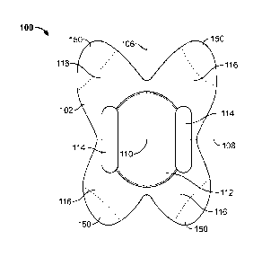
fluid from the back
sheet on one side of the fold to the back sheet on the other side of the fold
by virtue of this
contact.
[0054] The back sheet may be made from any suitable non-woven or
woven
materials, such as described in more detail above. For example, in some
variations the back
sheet may formed from one or more hydroentangled non-woven materials, such as,
for example
Suominen WL784450. The back sheet is preferably formed from one or more
biodegradable
materials, which may contribute to the flushability of the body liner. The
back may have any
suitable size. For example, the back sheet may have a thickness of about 1 mm,
between about
0.5 mm and about 1.5 mm, or the like. In some variations, the back sheet may
be configured
such that one or more portions of the body liner may be at least partially
visualized through the
back sheet, such as described above. For example, in variations where the body
liner comprises
a top sheet, a back sheet, and a core member positioned between the top sheet
and the back sheet,
17
CA 02863163 2014-07-29
WO 2013/116391 PCT/US2013/023928
the back sheet may be configured to allow for visualization of the core member
through the back
sheet.
Exemplary body liner construction
[0055] FIGS. 1A-1E depicts an illustrative variation of the body
liners described
here. FIGS. 1A and 1B show top and bottom views, respectively of a variation
of a body liner
(100). The body liner (100) may have a body-facing surface (102) (as shown in
FIG. 1A) and a
rear surface (104) (shown in FIG. 1B) opposite the body-facing surface (102).
The body liner
(100) may include a longitudinal axis (106) and a lateral axis (108) within
the plane of the body
liner (100). The longitudinal (106) and lateral (108) axes are orthogonal, and
may intersect at a
target point (110). When the body liner (100) is placed at least partially
within the intergluteal
cleft, it is intended that the body liner be positioned such that the target
point (110) is positioned
over the anus at or near the anus of the wearer and the body liner (100) be
folded substantially
along the longitudinal axis (106). It should be appreciated that the
longitudinal axis, the lateral
axis, and the target point are relative terms which may be useful in
describing the size, shape,
and features of the body liners described here. While the target point (110)
is shown in FIGS.
lA and 1B as positioned near the center of the body liner (100), it should be
appreciated that in
some instances it may be desirable to configure a body liner such that the
target point is offset
from the center of the body liner. For example, in some variations a target
point may positioned
closer to a front end of the body liner than a back end of the body liner,
which may facilitate
urination when the body liner is in place.
[0056] Also shown in FIGS. IA and 1B is a target zone (112).
Generally, a target
zone (112) surrounds the target point (110) and is intended as the primary
region of the body
liner for receiving bowel leakage. When the target zone (112) receives a load
of bowel leakage,
the target zone (112) may be configured to dewater and immobilize the leakage.
It may be
desirable to configure the body liner (100) to allow the target zone (112) to
dewater an
anticipated ABL load. For example, the target zone (112) may be configured to
dewater an ABL
load of at least about .05 ml. In some of these variations, the target zone
(112) may be
configured to dewater an ABL load of .25 ml or more, and in some of these
variations the target
zone (112) may be configured to dewater an ABL load of 5 ml or more. The
target zone (112)
may be any suitable size or shape. In some variations, the target zone (112)
may have an area
between about 25 cm2 and about 55 cm2. In some of these variations, the target
zone (112) may
18
CA 02863163 2014-07-29
WO 2013/116391 PCT/US2013/023928
preferably have an area between about 30 cm2 and about 50 cm2. In some of
these variations, the
target zone (112) may have an area between about 35 cm2 and about 45 cm2. In
some instances
that target zone may have at least a 3 cm radius from the target point. The
target zone (112) may
be oval, rectangular, hourglass shaped, irregularly shaped, or the like, as
will be described in
more detail below.
[0057] Additionally, in some variations it may be desirable to limit
the amount of
absorbed fluid that travels beyond the target zone (112). For example, when
one or more
portions of the body liner is configured to extend at least partially from the
intergluteal cleft
(e.g., so that a wearer can grasp the exposed portion or portions to remove
the body liner),
limiting the ability of fluid absorbed to travel past the target zone and to
the exposed portions of
the body liner may reduce the likelihood that the wearer will soil his or her
fingers when
removing the body liner (100). While the target zone (112) is shown in FIGS.
IA and I B as
being centered on the target point (110), the target zone (112) need not be.
In some variations,
the boundaries of the target zone may be defined by the boundaries of a core
member, such as
will be described in more detail below.
[0058] The target zone of a body liner may be configured to have one
or more
properties that are different than those of surroundings portions of the body
liner. In some
variations, the target zone of a body liner may be configured to have a
greater absorbency than
surrounding portions of the body liner. For example, in some variations the
target zone may
have a thickness greater than the thickness of surrounding portions of the
body liner, which may
allow for greater fluid absorption relative to thinner portions of the body
liner. Additionally or
alternatively, the target zone may include one or more additional liner layers
which may increase
the absorbency of the target zone. Additionally or alternatively, the target
zone may be formed
from a different material or materials than the material or materials of the
surrounding portions
of the body liner. In these variations, the material or combination of
materials forming the target
zone may be more absorbent than the material or combination of materials
forming the
surrounding portions of the body liner. Additionally or alternatively, the
target zone may be
imbedded with one or more absorbent particles, such as one or more super
absorbent polymers,
which may increase the absorbency of the target zone.
[0059] The body liner (100) shown in FIGS. lA and 1B has a target
zone (112)
having an oval shape, but it should be appreciated that the body liners
described here (including
19
CA 02863163 2014-07-29
WO 2013/116391 PCT/US2013/023928
the body liner (100)) may have a target zone having any suitable shape (e.g.,
a circular shape, a
square or rectangular shape, a triangular shape, an hourglass shape, an
irregular shape, or the
like). Additionally, the body liner (100) shown in FIGS. lA and 1B is shown as
having an
overall butterfly shape having four lobes (116) extending from the target zone
(112), it should be
appreciated that the body liners described here may have any suitable shape,
such as will be
described in more detail below.
[0060] In some instances, it may be desirable to configure the body
liners
described here to avoid contact with or occlusion of the genitals of the
wearer. For example, in
instances in which a female wearer positions a body liner at least partially
in the intergluteal cleft
to position a target point at the intergluteal cleft, it may be desirable to
configure the body liner
to not occlude the vagina. If a portion of the body liner occludes the vagina
or is positioned too
close to the vagina, the body liner may absorb urine or menstrual fluid from
the vagina, which
may require removal of the body liner. In other variations, contact between
the body liner and
the genitals may cause bunching of the body liner and/or discomfort to the
wearer. Accordingly,
the body liner may be configured to avoid contact with or occlusion of
genitals. For example, in
the illustrative variation of the body liner (100) shown in FIGS. IA and I B,
the length of the
body liner (100) along the longitudinal axis (106) between the target point
(110) and the front
end of the body liner (100) may be less than the distance between the anus and
the genitals. In
some variations the length of the body liner (100) along the longitudinal axis
(106) between the
target point (110) and the front end of the body liner (100) may be less may
be less than about
3.5 cm.
[0061] The body liner (100) shown in FIGS. lA and 1B may be formed
from one
or more liner layers, such as discussed briefly above. FIGS. 1C-1E depict
different variations in
which the body liner (100) may be formed from one or more liner layers. FIG.
1C depicts a
cross-sectional side view (taken along the longitudinal axis (106)) of a
variation in which the
body liner (100) may be formed from a first liner layer (118) (e.g., a top
sheet such as those
described above). In some of these variations, the first liner layer (118) may
be the only liner
layer of the body liner (100). As shown in FIG. 1C, the first liner layer
(118) may have a body-
facing side (120) and a rear side (122) opposite the body-facing side (120).
The body-facing side
(120) of the first liner layer (118) may form the body-facing surface (102) of
the body liner (100)
and the rear side (122) of the first liner layer (118) may form the rear
surface (104) of the body
CA 02863163 2014-07-29
WO 2013/116391 PCT/US2013/023928
liner (100). In some variations, such as that shown in FIG. 1C, the first
liner layer (118) may
have a greater thickness in the target zone (112) than in the surrounding
portions of the body
liner (100). The increased thickness of the target zone (112) may increase the
overall
absorbency of the target zone (112). It should be appreciated, however, that
in other instances
the target zone (112) may have the same thickness as or a smaller thickness
than surrounding
portions of body liner (for example, in instances where the target zone (112)
may comprise one
or more absorbent agents imbedded therein).
[0062] FIG. 1D depicts a cross-sectional side view (taken along the
longitudinal
axis (106)) of a variation in which the body liner (100) may comprise two
liner layers. As shown
there, the body liner (100) may comprise a top sheet (124) and a core member
(126). In some of
these variations, the top sheet (124) and core member (126) may be the only
liner layers of the
body liner. The top sheet (124) and the core member (126) may be any
combination of the top
sheets and core members such as those described in more detail above. The top
sheet (124) and
core member (126) may each have a body-facing side ((128) and (132),
respectively) and a rear
side ((130) and (134), respectively) opposite the body-facing side. At least a
portion of the
body-facing side (132) of the core member (126) may be attached to the rear
side (130) of the
top-sheet (124) to connect the liner layers, as will be described in more
detail below. In the
variation shown in FIG. 1D, the body-facing side (128) of the top sheet (124)
may form the
body-facing surface (102) of the body liner (100), while the rear side (134)
of the core member
(126) and the portion of the rear side (130) of the top sheet (124) not
covered by the core
member (126) may form the rear surface (104) of the body liner (100).
Additionally, in some of
these variations, the size and shape of the core member (126) may define the
boundaries of the
target zone (112).
[0063] FIG. lE depicts a cross-sectional side view (taken along the
longitudinal
axis)) of a variation in which the body liner (100) may comprise three liner
layers. As shown
there, the body may comprise a top sheet (124) and a core member (126) (which
are labeled as
set forth in FIG. 1D), and may further comprise a back sheet (127). In some
variations, the top
sheet (124), core member (126), and back sheet (127) may be the only liner
layers of the body
liner. The back sheet (127) may have a body-facing side (136) and a rear side
(138) opposite the
body-facing side (136). In the variation shown in FIG. 1E, the core member may
be enclosed
between the top sheet (124) and the back sheet (127). In these variations, top
sheet (124) and
21
CA 02863163 2014-07-29
WO 2013/116391 PCT/US2013/023928
back sheet (127) may be connected, as will be described in more detail below.
In some of these
variations, the core member (126) may also be attached to top sheet (124)
and/or the back sheet
(127). In the variation shown in FIG. 1E, the body-facing side (128) of the
top sheet (124) may
form the body-facing surface (102) of the body liner (100) and the rear side
(138) of the back
sheet (127) may form the rear surface (104) of the body liner (100). In some
of these variations,
the size and shape of the core member (126) may define the boundaries of the
target zone (112).
[0064] As shown in FIGS. IA, the body liner (100) may comprise one or
more
adhesive regions (114) on the body-facing surface (102) of the body liner
(100). In the variation
shown in FIG. 1A, the body liner (100) has an adhesive region (114) on each
side of the
longitudinal axis (106), although it should be appreciated that in some
variations the body liner
(100) may only have one or more adhesive regions (114) on one side of the
longitudinal axis
(106). In some variations, the body liner (100) may have one or more adhesive
regions that cross
the longitudinal axis (106). In still other variations, the body liner (100)
may not comprise any
adhesive regions. The size, shape, and placement of adhesive regions for use
with the body
liners described here will be described in more detail below.
Body liner Retrieval
[0065] The body liners described here may be constructed and arranged
to allow
for removal of the body liner from the intergluteal cleft. Specifically, it
may be desirable to
configure the body liners to allow for removal of the body liner while
minimizing the likelihood
that the wearer soils his or her fingers during removal of the body liner. For
example, one or
more retrieval devices may be attached to the body liner. In some of these
variations, a string,
ribbon, tab, or the like may be attached to one or more portions of the body
liner (e.g., via an
adhesive, welding, or the like). In these variations, when the body liner is
placed at least
partially within the intergluteal cleft, the string or ribbon may be
positioned to extend at least
partially out of the intergluteal cleft. To remove the body liner (e.g., after
a bowel leakage
incident), a wearer may pull on the string or ribbon to pull the body liner
away from the
intergluteal cleft.
[0066] In some variations, the body liner may be sized and configured
to extend
at least partially from the intergluteal cleft when positioned. For example,
in variations in which
the body liner comprises one or more lobes, one or more of the lobes may
extend at least
22
CA 02863163 2014-07-29
WO 2013/116391 PCT/US2013/023928
partially from the intergluteal cleft. FIG. 1F shows the illustrative
variation of the body liner
(100) (described above with respect to FIGS. lA and 1B) placed at least
partially within the
intergluteal cleft (140). As shown there, the body liner (100) may be folded
along the
longitudinal axis (106) and positioned such that the target point (110) is
positioned at or near the
anus (142). The body liner (100) may be sized such that when the target point
(110) is
positioned at or near the anus (142), at least a portion of one or more of the
lobes (116) may
extend at least partially outside of the intergluteal cleft. The portion of
the body liner that
extends from the intergluteal cleft is preferably large enough to allow a
wearer to grasp the
exposed portion of the body liner. In some of these variations, the body liner
may be sized and
configured such that at least a portion of the body liner (e.g., one or more
lobes) extends at least
1 cm from the intergluteal cleft when the target point (110) is positioned at
or near the anus
(142)). The wearer of the body liner may grab one or more of the exposed
portions of the body
liner, and may pull on the body liner to remove the body liner from the
intergluteal cleft. By
allowing the wearer to remove the body liner without reaching into the
intergluteal cleft, a
wearer is less likely to soil his or her fingers when removing the body liner.
[0067] While it may be desirable for at least a portion of the body
liner to extend
from the intergluteal cleft, it may also be desirable to limit the amount of
extension of the body
liner from the intergluteal cleft. If the body liner extends too far from the
intergluteal cleft,
clothing may catch or snag the body liner (e.g., when putting on or removing
undergarments or
pants) which may dislodge or displace the body liner from its intended
position. Accordingly, in
some variations the body liner may be sized, configured, and positioned such
that at least a
portion of the body liner extends out of the intergluteal cleft and the
portions of the body liner
extending out of the intergluteal cleft extend less than about 2.5 cm from the
intergluteal cleft.
In some of these variations, at least a portion of the portions of the body
liner extending out of
the intergluteal cleft may extend at least 1 cm out of the intergluteal cleft.
[0068] When the body liners described here are configured to extend
at least
partially from the intergluteal cleft, such as described immediately above, it
may be desirable to
limit the absorbance of the exposed portions of the body liner. In these
variations, decreasing the
absorbance of the exposed portions of the body liner may reduce the ability of
absorbed fluid to
reach the exposed portions of the body liner, thereby reducing the likelihood
that a wearer will
grab a soiled portion of the body liner during removal of the body liner. In
some variations, the
23
CA 02863163 2014-07-29
WO 2013/116391 PCT/US2013/023928
exposed portions of the body liner may be crimped, crushed, or otherwise
compressed to reduce
the absorbance of the exposed portions. For example, when the body liner
comprises one or
more lobes that are configured to extend at least partially from the
intergluteal cleft (such as
lobes (116) of the body liner (100) described above with respect to FIG. 1F),
the lobes may be
crimped, crushed, or otherwise compressed. Additionally or alternatively, the
exposed portions
of the body liner may be covered by one or more fluid-impervious materials. In
these variations,
if fluid absorbed by the body liner reaches the exposed portions of the body
liner, the fluid-
impervious covering may prevent fluid from being transferred to the wearer's
fingers. For
example, in some of the variation of the body liner (100) described above with
respect to FIGS.
lA and 1B, lobes (116) may comprise coated regions (150) which may be coated
with one or
more fluid-impervious materials. While each of the lobes (116) are shown in
FIGS lA and 1B
as having a coated region (150), it should be appreciated that only some of
the lobes (e.g., only
the lobes on a first side of the lateral axis (108), only the lobes on a first
side of the longitudinal
axis (106), or the like) may comprise a coated region (150).
Flushability
[0069] In some variations, the body liners described here may be
configured to be
entirely flushable. Panty liners, menstrual pads and incontinence pads
generally are not
flushable, by virtue of their relatively large size and/or the presence of
fluid-impermeable layers.
When a product is not flushable, a wearer must find alternative means of
disposal for the
product, or risk clogging a toilet by attempting to flush the device (which
may create an
embarrassing situation for the wearer). The odors associated with anal leakage
may make
discreet disposal of fecal incontinence pads difficult, especially in public
restrooms where trash
receptacles are generally not provided in individual stalls. Accordingly, it
may be desirable to
configure the body liners described here to be flushable for discreet disposal
in a toilet.
[0070] When the body liners described here are configured to be
flushable, they
may be configured to be flushable based on INDA and/or EDANA guidelines (e.g.,
the body
liner may clear properly-maintained toilets and pipe systems under expected
product usage
conditions and may be compatible with existing wastewater disposal systems).
In some of these
variations, the body liner may be configured to dispersible based on INDA
and/or EDANA
guidelines. In some variations, the body liner may be configured to use little
or no non-
biodegradable materials. In some of these variations, less than 10% of the
mass of the body liner
24
CA 02863163 2014-07-29
WO 2013/116391 PCT/US2013/023928
may be formed from non-biodegradable materials. In some of these variations,
less than 5% of
mass of the body liner may formed from non-biodegradable materials. In some
variations, each
of the liner layers is formed from one or more biodegradable materials (each
liner layer may be
formed from the same biodegradable material or combination of biodegradable
materials, or
different liner layers may be formed from different biodegradable materials or
combinations of
biodegradable materials). In some variations, each of the liner layers is
formed from a
dispersible material. In some variations where the body liner comprises one or
more adhesive
regions, one or more adhesives of the adhesive regions may be the only non-
biodegradable
component of the body liner. In these variations, the size and placement of
adhesive regions
may be configured so as to not interfere with the flushability of the body
liners.
[0071] When a body liner is configured to be flushable, the body
liner is
preferably made using materials that facilitate or otherwise promote
dissolution of the product
when disposed in a toilet. For example, in variation where a body liner
comprises two or more
liner layers that may be at least partially bonded together, as will be
described in more detail
below, the liner layers may be bonded using one or more water-soluble resins.
The liner layers
of the flushable body liners are preferably made of cellulosic materials, such
as one or more
woven or nonwoven materials formed using cellulosic fibers. These cellulosic
materials need
not include long synthetic fibers, which may promote di spersibility of the
body liner. For
example, in variations where a body liner comprises a combination of a top
sheet, a core
member, and/or a back sheet such as those described above, each of the liner
layers may be
formed from one or more cellulosic materials. Because the body liners are
typically removed
shortly after soiling, the body liner may be removed prior to significant
dissolution of the
dissolvable or dispersible body liner components. When the body liner is
packaged with one or
more release liners, it should be appreciated that the release liner need not
be flushable, although
the release liner may also be flushable.
[0072] It may also be desirable to minimize the overall size of a
body liner to
facilitate flushing of the body liner. By placing a target point (and in some
instances a target
zone) of the body liner at or near the anal opening, the body liner may trap
ABL loads near the
anal opening, which may allow the overall bulk of the body liners to be
reduced relative to panty
liners, diapers, and the like. Additionally, in some variations, the body
liners may be
impregnated with one or more absorbent materials (e.g., one or more super-
absorbent polymers)
CA 02863163 2014-07-29
WO 2013/116391 PCT/US2013/023928
which may allow for increased absorption by the body liner without
significantly increasing the
overall bulk of body liner. In these variations, any liner layer or liner
layers (e.g., a top sheet, a
back sheet, a core member, combinations thereof, or the like) may be
impregnated with these
polymers. It should be appreciated, however, that the body liner described
here may be able to
immobilize and/or absorb a load of anal leakage without the need for super
absorbent polymers.
Furthermore, in variations of the body liners described here that do not
include a fluid-
impermeable layer, the absence of a fluid-impermeable layer may reduce the
size of the body
liners (and also may remove the flushing liability that may occur due to the
layer's fluid
impermeability).
Multi-Ply construction
[0073] When the body liners described here comprise a plurality of
liner layers,
some or all of the plurality of liner layers may be connected in any suitable
manner. The layers
may be formed individually from the respective raw materials for each layer.
For example, in
some variations, a top sheet layer may be formed from an airlaid non-woven
material having a
high loft and softness, a core member layer may be formed from a wet-laid non-
woven material,
and a back sheet may be formed from a hydroentangled non-woven material. The
individual
layers of the body liner may be placed in contact with each other, and may be
connected in one
or more manners. For example, two core layers may be bonded together using one
or more
adhesives. Additionally or alternatively, two layers may be mechanically
connected.
[0074] When two liners layers are connected using one or more
adhesives, one or
more adhesives may be applied to one or both of the liner layers and the liner
layers may be
placed into contact with each other such that the one or more adhesive joins
the liner layers. The
adhesive may be any suitable adhesive (e.g., one or more hot melt adhesives
such as DEMRA-
TAK H 542B, Henkel EASYMELTO 34-375C, one or more solvent-based adhesives, one
or
more water-based adhesives, one or more energy-, heat-, or chemically-cured
adhesives,
combinations thereof and the like) and may be applied in any suitable manner
(e.g., spray
application, slot die coating, or the like). Rolling drums, one or more
presses, or the like may be
used to apply pressure to the liner layers. In some instances, these devices
may be heated or
cooled to help control the adhesive properties.
26
CA 02863163 2014-07-29
WO 2013/116391 PCT/US2013/023928
[0075] When the two layers are mechanically connected, they may be
connected
in any suitable manner, such as, for example, sewing, embossing, crimping,
ultrasonic bonding,
thermal bonding, needle punching, entanglement (e.g., fluid entanglement), or
the like. For
example, in some instances, two or more layers may be joined via entanglement.
In these
instances, a needle or other penetrating mechanism (e.g., a high pressure air
or water stream)
may penetrate through the liner layers to entangle fibers of the liner layers.
Additionally or
alternatively, the penetration mechanism may drive one or more long fibers
through the liner
layers to mechanically tie the liner layers together.
[0076] For example, in some variations where the body liner comprises
a top
sheet and a core member in contact with the top sheet, such as described in
more detail below,
the core member may be connected directly to the top sheet. In some
variations, the core
member may be bonded to the top sheet using one or more adhesives. For
example, in some
variations, the core member may be bonded to the top sheet using a water
soluble resin.
Additionally or alternatively, the core member may be mechanically connected
to the top sheet,
such as described in more detail above.
[0077] In variations where a body liner further comprises a core
member and a
back sheet in contact with the core member, the core member may be attached to
the back sheet
in any manner such as described immediately above. In variations where a body
liner comprises
a top sheet, a back sheet, and a core member positioned between the top sheet
and the back sheet,
any or all of the liner layers may be joined together in any suitable manner
such as those
described above (e.g., adhesive bonding and/or mechanical connection). For
example, in some
of these variations, the top sheet and back sheet may be directly connected,
and the core member
may be attached to one or both of the top sheet and back sheet.
[0078] When the core member is enclosed between a top sheet and a
back sheet,
the core member need not be directly attached to either the top sheet or the
back sheet. In these
variations, the top sheet and the back sheet may be connected to enclose and
retain the core
member in between the top sheet and back sheet. It may still be desirable for
the core member to
be attached to the top sheet and/or back sheet to help prevent relative
movement between the
core member and the top and back sheets. In these instances, only a small
portion of the core
member need be attached to the top sheet and/or the back sheet. For example,
in some
variations, the core member may be directly connected to the back sheet (e.g.,
using adhesive
27
CA 02863163 2014-07-29
WO 2013/116391 PCT/US2013/023928
bonding and/or mechanical connection) such that less than about 15% of the
surface area of the
core member may be attached to the back sheet. Additionally or alternatively,
the core member
may be directly connected to the top sheet (e.g., using adhesive bonding
and/or mechanical
connection) such that less than about 15% of the surface area of the core
member may be
attached to the top sheet.
[0079] In variations where a body liner comprises a back sheet and a
top sheet
(and, in some variations, a core member positioned therebetween), the back
sheet and the top
sheet may be directly connected and/or indirectly connected (e.g., connected
via a common
attachment to a liner layer such as a core member). In some instances, it may
be desirable for the
back sheet and the top sheet to be substantially unconnected. For example,
friction between
folded-over rear surfaces may cause the body liner to slip relative to skin of
the buttocks during
movement, which may result in bunching or displacement of the body liner, as
described in more
detail above. When the top sheet and back sheet are largely unconnected, the
top sheet may be
able to slip relative to the back sheet during wearer movement, and this
movement may help
prevent dislodgement and/or bunching of the body liner (especially in
variations where the rear
surface of the body liner has a low coefficient of friction). Additionally,
adhesive bonding
between liner layers may interfere with the ability of the body liner to
absorb fluid, may affect
the flushability of the liner layer, and/or may increase the stiffness of the
body liner (which may
decrease the level of comfort provided by the body liner). Accordingly, it may
be desirable to
join liner layers while minimizing the proportion of the surface area of the
liner layers that are
connected. In some variations, the top sheet and the back sheet may be
connected such that at
least 80 percent of surface areas of the top sheet and back sheet remain
unconnected. In some of
these variations, at least 90 percent of the surface areas of the top sheet
and the back sheet
remain unconnected.
[0080] When the back sheet and top sheet are directly connected, they
may be
connected in any suitable manner such as described in more detail above (e.g.,
via adhesive
bonding and/or mechanical attachment). In some variations, the back sheet and
the top sheet
may be connected around the periphery of the top sheet and/or back sheet. In
some of these
variations, the back sheet and the top sheet may be connected around the
entire periphery of the
top sheet and/or back sheet. In variations where the top sheet and the back
sheet have the same
shape, the top sheet and the back sheet may be joined around the peripheries
of both the top sheet
28
CA 02863163 2014-07-29
WO 2013/116391 PCT/US2013/023928
and the back sheet. In variations where the top sheet is larger than the back
sheet, the top sheet
and back sheet may be joined around the periphery of the back sheet, or vice
versa.
[0081] When multiple layers are joined to form a body liner, the
shape of the
body liner may be created before or after the liner layers are joined. For
example, in some
variations the shape of individual liner layers may be set prior to joining
the liner layers (e.g.,
individual liner layers may be cut to the desired shape of the body liner
prior to construction of
the body liner) or the body liner may be set into a desired shape after the
liner layers have been
joined (e.g., the multi-layer construction may be cut into the desired body
liner shape).
Additionally, in some instances (such as described in more detail below), one
or more adhesive
regions may be applied to the body liner. The body liner or individual liner
layers may be cut in
any suitable manner, such as die cutting, laser cutting, water jet cutting, or
the like.
Absorption
[0082] As mentioned above, the body liners described here may be
configured to
be fluid absorbent. The body liners described here may be able to absorb any
suitable amount of
fluid, depending on the size and materials of the body liners. In some
variations, a body liner
may have an overall absorbency index of at least about 1.25 g/g. When fluid is
absorbed by the
body liner, the absorbent material may be configured acquire, distribute, and
store fluid absorbed
by the liner (e.g., via porosity and/or capillarity of the materials). In some
variations, at least a
portion of the body liner may be configured to be absorbent such that is may
pass body fluid
from a body-facing surface to an opposite-facing rear surface of the body
liner. In these
variations, the body liner may be configured to wick or otherwise transfer
fluid via rear surface-
to-rear surface contact between body liner portions of different sides of a
fold line (such as when
folded along a longitudinal axis such as described in more detail above), such
as when the rear
surfaces of body liner include absorbent materials. When the body liners
described here
comprise a plurality of liner layers (e.g., a top sheet and a back sheet
and/or core member), some
or all of the liner layers may be configured to be fluid absorbent. In some
variations, each of the
liner layers may be configured to be fluid absorbent. In these variations, the
body liner may be
able to transfer fluid from a body-facing surface through the plurality of
liner layers and to a rear
surface of the body liner (e.g., each liner layer may be able to transfer
fluid from a body-facing
side of the liner layer to a rear side of the liner layer). Additionally, the
absorbent nature of the
29
CA 02863163 2014-07-29
WO 2013/116391 PCT/US2013/023928
body liner (and the liner layers thereof) may allow for gas to pass
therethrough, which may
thereby provide breathability of the body liner and reduce of moisture by the
body liner.
[0083] In some variations above, it may be desirable to configure the
body liner
to selectively distribute fluid absorbed by the body liner. Specifically, the
body liner may be
configured to have different fluid wicking rates in different directions. FIG.
2A shows a
perspective view of an illustrative variation of a body liner (200). The body
liner (200) may be
any of the body liners described hereinthroughout, and may have any suitable
size, shape, and
configuration of features. As shown in FIG. 2A, movement of fluid at a given
point (201) may
be divided into three component directions (i.e., a first direction (202), a
second direction (204),
and a third direction (206)). As shown there, the first (202) and second (204)
directions may be
perpendicular to each other within the plane of the body liner (200). The
third direction (206)
may be perpendicular to the plane of the body liner (200) (and may thereby be
perpendicular to
both the first (202) and second (204) directions) and may extend across the
thickness of the body
liner (200). The body liners described here may be configured to selectively
control the rate of
fluid movement in the first, second, and third directions.
[0084] For example, in some variations, it may be desirable to
configure a body
liner (or one or more liner layers of a body liner) such that fluid moves more
quickly through the
thickness of a body liner (or liner layer thereof) than it does within the
plane of the body liner (or
liner layer thereof). For example, in the illustrative variation of the body
liner (200) shown in
FIG. 2A, the body liner (200) may have a wicking rate in the third direction
(206) that is greater
than wicking rates in the first (202) and second (204) directions. In these
instances, fluid that
contacts the body liner (e.g., from a load of bowel leakage) may pass more
quickly through the
body liner (e.g., from a skin-facing surface of the body liner toward a rear
surface of the body
liner) than it spreads across the body liner. This may promote absorption
across the thickness of
the body liner and may reduce the spreading of the fluid load when applied to
the body liner.
Reducing spread of the fluid absorbed by the body liner may reduce the
likelihood that fluid will
reach the exterior portion of the body liner, thereby reducing the likelihood
that a wearer will
touch a soiled portion of the body liner when removing the body liner.
[0085] Additionally, when the body liner is substantially folded back
on itself
(e.g., folded along the longitudinal axis when placed at least partially in
the intergluteal cleft),
the fluid that contacts the body liner on one side of the fold line may be
transferred through the
CA 02863163 2014-07-29
WO 2013/116391 PCT/US2013/023928
thickness of body liner and may be further transferred to a portion of the
body liner on the other
side of the fold (e.g., via the rear surface-to-rear surface contact). For
example, FIG. 2B shows a
front view of the body liner (200) shown in FIG. 2A, in which the body liner
(200) has been
folded in half along a longitudinal axis (not shown). As shown there, fluid
passing in the third
direction (206) relative to point (201) will move toward the opposite half of
the body liner along
the third direction (206), and may be absorbed by the opposite half of the
body liner along the
third direction (206). This may increase the overall amount of fluid that is
absorbed in the third
direction (206), which may further reduce the amount of fluid that may spreads
in the first (202)
and second (204) directions for a given fluid load. This may help to localize
fluid relative to its
initial contact point, which is typically close to the anus. When one or more
portions of the body
liner extends at least partially out of the intergluteal cleft, this
localization may reduce the
likelihood that fluid reaches the exposed portion or portions of the body
liner.
[0086] In some variations it may be desirable to configure the body
liner (or a
liner layer thereof) to transfer fluid at different rates within the plane of
the body liner (or liner
layer thereof). For example, in variations where the body liner comprises one
or more air-laid
non-woven materials, the fibers of the material may be laid such that fibers
are more aligned in a
first direction than a second direction. For example, in the illustrative
variation of the body liner
(200) shown in FIGS. 2A and 2B, a wicking rate in the first direction (202)
may be greater than a
wicking rate in the second direction (204) (or vice versa). In these
variations, a fluid load
applied to the body liner (200) may spread more in the first direction (202)
than in the second
direction (204). This may find particular utility in instances where one or
more portions of a
body liner extend beyond the intergluteal cleft to act as a retrieval portion
which the wearer can
grasp and pull to remove the body liner from the intergluteal cleft. In these
variations, it may be
desirable to minimize the likelihood that fluid reaches the retrieval portions
of the body liners.
For example, in the variation of the body liner (100) described above with
respect to FIGS. 1A-
1E, the body liner (100) may be configured such that at least a portion of one
or more of these
lobes (116) may extend at least partially from the intergluteal cleft when the
body liner (100) is
placed at least partially within the intergluteal cleft. These exposed
portions of the lobes (116)
are positioned either above or below the lateral axis (108). Accordingly, in
these variations, it
may be desirable to configure the body liner (100) such that a wicking rate in
a direction parallel
to lateral axis (108) is greater than a wicking rate in a direction parallel
to the longitudinal axis
(106). In these variations, when a load of anal leakage contacts the body
liner (e.g., in the target
31
CA 02863163 2014-07-29
WO 2013/116391 PCT/US2013/023928
zone (112)), fluid from the load may spread across the width of the body liner
faster than it
spreads along the length of the body liner. Accordingly, a smaller amount of
fluid may spread
along the longitudinal axis toward the lobes (116), which may decrease the
likelihood that fluid
will be able to travel far enough to reach the exposed portions of the lobes
(116).
[0087] When the body liners described here are configured to have a
wicking rate
in a first direction within a plane of the body liner (e.g., first direction
(202) of body liner (200))
that is greater than a wicking rate in a second direction within a plane of
the body liner (e.g.,
second direction (204) of the body liner (200)), the first and second
directions may be any
suitable direction in the body liner. For example, in some of the variations,
the first direction
may be parallel to the longitudinal axis and the second direction may be
parallel to the lateral
axis (e.g., fluid may travel along the longitudinal axis faster than it
travels along the lateral axis).
In others of these variations, the first direction may be parallel to the
lateral axis, and the second
direction may be parallel to the longitudinal axis (e.g., fluid may travel
along the lateral axis
faster than it travels along the longitudinal axis). In still others of these
variations, the first
direction may be angled relative to the longitudinal axis. In these
variations, the angle between
the first direction and the longitudinal axis may be any suitable angle (e.g.,
about 30 degrees.
about 45 degrees. about 60 degrees, or the like). Because the first and second
directions are
perpendicular to each other, the angle between the second direction and the
lateral axis may be
the same as the angle between the first direction and the longitudinal axis.
[0088] When the body liners described here are configured to have a
wicking rate
in a first direction within a plane of the body liner (e.g., first direction
(202) of body liner (200))
that is greater than a wicking rate in a second direction within a plane of
the body liner (e.g.,
second direction (204) of the body liner (200)), the wicking rate across the
thickness of the body
liner (e.g., third direction (204) of the body liner (200)) may be any
suitable value relative to the
wicking rates in the first and second directions. For example, in some
variations, the wicking
rate in the third direction may be greater than the wicking rates of both the
first and second
directions, such as described in more detail above. In other variations, the
wicking rate in the
third direction may be approximately equal to the wicking rate in the first
direction. In still other
variations, the wicking rate in the third direction may be less than the
wicking rate in the first
direction, but may be greater than the wicking rate in the second direction.
In yet other
variations, the wicking rate in the third direction may be approximately equal
to the wicking rate
32
CA 02863163 2014-07-29
WO 2013/116391 PCT/US2013/023928
in the second direction. In still other variations, the wicking rate in the
third direction may be
less than the wicking rates in both the first and second directions. It should
be appreciated that
while described above as having different wicking rates in the first, second,
and/or third
directions, it should be appreciated that in some variations, a body liner (or
a liner layer thereof)
may be configured to uniformly distribute absorbed fluid (e.g., the wicking
rates in each
direction of the body liner are approximately equal).
[0089] In variations where the body liner comprises a plurality of
layers, any or
all of the liner layers may be configured to selectively distribute fluid in
any manner as described
above. The movement of fluid within each liner layer may be characterized
based on wicking
rates in three component directions. specifically a first direction in a plane
of the body liner, a
second direction in a plane of the body liner that is perpendicular to the
first direction, and a third
direction extending through the thickness of the body liner and perpendicular
to both the first and
second directions, such as described above. The wicking rate for a given
direction in one liner
layer may be the same as or different from the wicking rate for that direction
in another liner
layer.
[0090] For example, in some variations where a body liner comprises a
top sheet,
the top sheet may be configured to have a wicking rate in the top sheet in the
third direction that
is greater than a wicking rate in the top sheet in the first direction and
greater than a wicking rate
in the top sheet in the second direction. In these variations, fluid may be
transferred across the
thickness of the top sheet more quickly than it spreads across the body liner,
which may allow
for effective transfer of fluid from the top sheet to one or more additional
liner layers (e.g., a core
member and/or a back sheet). In some of these variations the wicking rate in
the first direction
may be greater than the wicking rate in the second direction, or vice versa.
In others of these
variations, the wicking rate in the first direction may be equal to wicking
rate in the second
direction.
[0091] In other variations, the top sheet may be configured to have a
wicking rate
in the top sheet in the third direction that is less than a wicking rate in
the top sheet in the first
direction and less than a wicking rate in the top sheet in the second
direction. In these variations,
absorbed fluid may spread across the top sheet faster than it is transferred
across the thickness of
the top sheet. In some of these variations the wicking rate in the first
direction may be greater
33
CA 02863163 2014-07-29
WO 2013/116391 PCT/US2013/023928
than the wicking rate in the second direction, or vice versa. In others of
these variations, the
wicking rate in the first direction may be equal to wicking rate in the second
direction.
[0092] In still other variations the top sheet may be configured to
have a wicking
rate in the top sheet in a third direction that is less than a wicking rate in
the top sheet in a first
direction and greater than a wicking rate in the top sheet in a second
direction. In yet other
variations, the top sheet may be configured to have a wicking rate in the top
sheet in a third
direction that is equal to the wicking rate in the top sheet in the first
direction. In some of these
variations, the top sheet may be configured such that a wicking rate in the
top sheet in the second
direction is greater than the wicking rates in the first and third directions.
In others of these
variations, the top sheet may be configured such that a wicking rate in the
top sheet in the second
direction is less than the wicking rates in the first and third directions. In
still other variations,
the top sheet may be configured to uniformly distribute fluid within the top
sheet (i.e., the top
sheet may be configured such that a wicking rate in the top sheet in the third
direction is equal to
a wicking rate in the top sheet in the first direction and a wicking rate in
the top sheet in a second
direction).
[0093] In some variations where a body liner comprises a core member,
the core
member may be configured to have a wicking rate in the core member in the
third direction that
is greater than a wicking rate in the core member in the first direction and
greater than a wicking
rate in the core member in the second direction (which may prioritize
absorption through the
thickness of the core member over spreading of the fluid sample across the
core member, such as
discussed above). In some of these variations the wicking rate in the first
direction may be
greater than the wicking rate in the second direction, or vice versa. In
others of these variations,
the wicking rate in the first direction may be equal to wicking rate in the
second direction.
[0094] In other variations, the core member may be configured to have
a wicking
rate in the core member in the third direction that is less than a wicking
rate in the core member
in the first direction and less than a wicking rate in the core member in the
second direction
(which may prioritize spread of the fluid over absorption across the thickness
of the core
member). In some of these variations the wicking rate in the first direction
may be greater than
the wicking rate in the second direction, or vice versa. In others of these
variations, the wicking
rate in the first direction may be the same as the wicking rate in the second
direction.
34
CA 02863163 2014-07-29
WO 2013/116391 PCT/US2013/023928
[0095] In still other variations the core member may be configured to
have a
wicking rate in the core member in a third direction that is less than a
wicking rate in the core
member in a first direction and greater than a wicking rate in the core member
in a second
direction. In yet other variations, the core member may be configured to have
a wicking rate in
the core member in a third direction that is equal to the wicking rate in the
core member in the
first direction. In some of these variations, the core member may be
configured such that a
wicking rate in the core member in the second direction is greater than the
wicking rates in the
first and third directions. In others of these variations, the core member may
be configured such
that a wicking rate in the core member in the second direction is less than
the wicking rates in the
first and third directions. In still other variations, the core member may be
configured to evenly
distribute fluid (e.g., may be configured such that a wicking rate in the core
member in the third
direction is equal to that a wicking rate in the core member in the first
direction and a wicking
rate in the core member in a second direction).
[0096] In some variations where a body liner comprises a back sheet,
the back
sheet may be configured to have a wicking rate in the back sheet in the third
direction that is
greater than a wicking rate in the back sheet in the first direction and
greater than a wicking rate
in the back sheet in the second direction (which may prioritize absorption
through the thickness
of the back sheet over spreading of the fluid sample across the core member,
such as discussed
above). In some of these variations the wicking rate in the first direction
may be greater than the
wicking rate in the second direction, or vice versa. In others of these
variations, the wicking rate
in the first direction may be the same as the wicking rate in the second
direction.
[0097] In other variations, the back sheet may be configured to have
a wicking
rate in the back sheet in the third direction that is less than a wicking rate
in the back sheet in the
first direction and less than a wicking rate in the back sheet in the second
direction (which may
prioritize spread of the fluid across the back sheet over absorption through
the thickness of the
back sheet). In some of these variations, the wicking rate in the first
direction may be greater
than the wicking rate in the second direction, or vice versa. In others of
these variations, the
wicking rate in the first direction may be equal to wicking rate in the second
direction.
[0098] In still other variations the back sheet may be configured to
have a
wicking rate in the back sheet in a third direction that is less than a
wicking rate in the back sheet
in a first direction and greater than a wicking rate in the back sheet in a
second direction. In yet
CA 02863163 2014-07-29
WO 2013/116391 PCT/US2013/023928
other variations, the back sheet may be configured to have a wicking rate in
the back sheet in a
third direction that is the same as the wicking rate in the back sheet in the
first direction. In some
of these variations, the back sheet may be configured such that a wicking rate
in the back sheet in
the second direction is greater than the wicking rates in the first and third
directions. In others of
these variations, the back sheet may be configured such that a wicking rate in
the back sheet in
the second direction is less than the wicking rates in the first and third
directions. In still other
variations, the back sheet may be configured to evenly distribute fluid (e.g.,
may be configured
such that a wicking rate in the back sheet in the third direction is equal to
that a wicking rate in
the back sheet in the first direction and a wicking rate in the back sheet in
a second direction.
[0099] When the body liners described here comprise a plurality of
liner layers
(e.g., a top sheet and a core member, a top sheet and a back sheet, or a top
sheet, a core member,
and a back sheet), the liner layers may be configured to transfer fluid in any
combination of
manners described above. For example, in some variations where a body liner
comprises a top
sheet, a back sheet, and a core member, the top sheet may be configured to
have a wicking rate
in the top sheet in the third direction that is greater than a wicking rate in
the top sheet in the first
direction and greater than a wicking rate in the top sheet in the second
direction. Similarly, the
back sheet may be configured to have a wicking rate in the back sheet in the
third direction that
is greater than a wicking rate in the back sheet in the first direction and
greater than a wicking
rate in the back sheet in the second direction. In some of these variations,
both the top sheet and
the back sheet may be configured to have wicking rates in the top sheet and
back sheet,
respectively, in the first direction that are greater than the wicking rates
in the top sheet and back
sheet, respectively, in the second direction. In others of these variations,
the top sheet may be
configured to have a greater wicking rate in the top sheet in the first
direction than a wicking rate
in the second direction and the back sheet may be configured to distribute
fluidly evenly between
the first and second directions, or vice versa. The core member may be
configured to distribute
fluid evenly within the core (e.g., the core member may be configured to have
equal wicking
rates in each of the first, second. and third directions) or may be configured
to selectively
transfer fluid such as described in more detail above. In some variations, the
core member may
be configured to have a wicking rate in the core member in the third direction
that is greater than
a wicking rate in the core member in the first direction and greater than a
wicking rate in the core
member in the second direction. The wicking rates in a given direction (e.g.,
in the third
36
CA 02863163 2014-07-29
WO 2013/116391 PCT/US2013/023928
direction) in each of the top sheet, back sheet, and core member may all be
the same, or may be
different.
[0100] In some instances, it may be desirable to configure the body
liners
described here such that fluid spreads faster in the body liner (i.e., within
the plane of the body
liner, in the first and second directions as described above) near the rear
surface than it spreads
near the body-facing surface. In these instances, when an ABL load contacts
and is absorbed by
the body liner, a larger portion of the fluid load will be absorbed and
retained near the rear
surface of the body liner. The absorbed bowel leakage may be more concentrated
toward the
rear surface of the body liner (which is folded over itself) and may result in
a smaller visible
soiled "spot" on the body-facing surface of the body liner, which may provide
the wearer with an
additional sense of security and reduce the likelihood that fecal matter
absorbed by the body liner
may rub off against the skin during removal of the body liner. In variations
where the body liner
comprises a single liner layer, the liner layer may be configured to spread
fluid in the plane of
the liner layer faster toward the rear surface than it spreads fluid near the
body-facing surface.
For example, the liner layer is formed from one or more non-woven materials,
the fibers of the
liner layer may have a higher distribution of horizontally-oriented fibers
near the rear surface
than near the body-facing surface, which promote spreading near the rear
surface. In variations
where the body liner comprises a plurality of liner layers, different liner
layers may be
configured to spread fluid at different rates. For example, in variations
where the body liner
comprises a top sheet, a core member, and optionally a back sheet, the core
member may be
configured to spread fluid in the plane of the body liner faster than the top
sheet spreads fluid in
the plane of the body liner. In variations where the body liner comprises a
back sheet, the back
sheet may be configured to spread fluid in the plane of the body liner faster
than the top sheet
and/or core member spreads fluid.
Body Liner Shape
[0101] The body liners described here may have any suitable shape,
such as, for
example, a circular or oval shape, a rectangular shape, a triangular shape, an
hourglass shape, a
lobed shape (e.g., a butterfly shape), an irregular shape, combinations
thereof and the like. It
should be appreciated that regardless of the shape of the body liner, the body
liner may be
configured to have any combination of features and liner layers described
hereinthroughout. The
overall shape of the body liner may be a factor of the shape of some or all of
the liner layers. For
37
CA 02863163 2014-07-29
WO 2013/116391 PCT/US2013/023928
example, in variations where a body liner comprises a single liner layer, the
shape of the body
liner may be the same as the shape of the single liner layer. In variations
where a body liner
comprises a plurality of liner layers, the shape of the body liner may be
dependent on how the
individual liner layers are positioned with respect to each other. For
example, in some instances
the largest liner layer may define the overall shape of the body liner. In
other instances where
two or more liner layers partially overlap, the overall shape of the body
liner may be defined by
the two or more liner layers.
[0102] As mentioned above, in some variations, the body liners may
have a
circular or oval shape. For example. FIGS. 3A-3E depict variations of a body
liner having an
oval shape. Specifically, FIG. 3A shows a top view of body liner (300) having
an oval shape.
As shown there, body liner (300) may have a longitudinal axis (306) and a
lateral axis (304)
perpendicular to the longitudinal axis (306) and intersecting the longitudinal
axis (306) at a
target point (308). When the body liner (300) is placed at least partially
within the intergluteal
cleft the body liner (300) may be folded along the longitudinal axis (306) to
position the target
point (308) at or near the opening of the anus. While the target point (308)
is shown in FIG. 3A
as being positioned at the center of the body liner (300), it should be
appreciated that the target
point (308) may be positioned at any suitable location on the body liner.
Additionally, while the
longitudinal axis (306) is shown in FIGS. 3A-3E as positioned along the minor
axis of the
overall oval shape of the body liner (300), it should be appreciated that the
longitudinal axis
(306) may be positioned along any suitable portion of the body liner. The body
liner (300) may
comprise one or more adhesive regions (not shown), as will be described in
more detail below.
[0103] Generally, the body liner (300) may be sized such that when
placed at
least partially within the intergluteal cleft, at least a portion of the body
liner (300) may extend
out of the intergluteal cleft. For example, FIG. 3B shows a cross-sectional
side view of a person
with the body liner (300) placed partially within the intergluteal cleft
(309). As shown there, the
body liner (300) may be positioned such that the target point (308) is
positioned at or near the
anus (311) and the body liner (300) is folded substanially along the
longitudinal axis (306).
When positioned as shown in FIG. 3B, at least a portion of the body liner
(300) extends outside
of the intergluteal cleft (309). Generally, the exposed portion of the body
liner (300) may extend
far enough outside the intergluteal cleft enough to allow a wearer to grasp
the body liner (300),
38
CA 02863163 2014-07-29
WO 2013/116391 PCT/US2013/023928
but not so far that the body liner (300) is snagged by clothing, such as
described in more detail
above.
[0104] The body liner (300) shown in FIGS. 3A and 3B may be made from
one
or more liner layers. For example, FIG. 3C shows a cross-sectional side view
(taken along the
longitudinal axis (306)) of a variation of the body liner (300) in which the
body liner (300)
comprises a single liner layer (310). In these variations, overall oval shape
of the body liner
(300) may be defined by the oval shape of the liner layer (310). Additionally,
a body-facing side
of the liner layer (310) may form the body-facing surface (312) of the body
liner (300) and an
opposite rear side of the liner layer (310) may form the rear surface (314) of
the body liner (300).
It should be appreciated that the body-facing surface (312) and rear surface
(314) of the body
liner (300) may be configured to have any respective coefficients of friction,
such as described in
more detail below.
[0105] The liner layer (310) may be configured to absorb fluid, such
as described
in more detail above. In some variations, the liner layer (310) may be
configured to selectively
transfer fluid as described above. For example, in some variations, the liner
layer (310) may be
configured to transfer fluid across the thickness of a body liner (e.g., in a -
third direction" as
discussed above, which may perpendicular to both the longitudinal axis (306)
and the lateral axis
(304)) at a wicking rate that is greater than wicking rates at which fluid is
transferred within the
plane of the body liner (e.g., in a "first direction" and "second direction"
as discussed above).
When the body liner (300) is folded over the longitudinal axis (306), a
greater wicking rate
across the thickness of the body liner (300) may promote transfer of fluid
from a contact point on
the body-facing surface (312) of the body liner on one side of the fold to the
rear surface (314)
on that side of the fold, and may further promote transfer from the rear
surface (314) to a
contacting rear surface (314) on the opposite side of the fold, as described
in more detail above.
Additionally or alternatively, the liner layer (310) may be configured to
transfer fluid in a first
direction in the plane of the body liner (300) at a wicking rate that is
faster than the wicking rate
in a second direction in the plane of the body liner (300) that is
perpendicular to the first
direction. For example, in some variations, the liner layer (310) may be
configured to transfer
fluid in a first direction parallel to the longitudinal axis (306) at a
wicking rate that is faster than
a wicking rate in a second direction parallel to the lateral axis (304). When
the body liner (300)
is placed at least partially in the intergluteal cleft as shown in FIG. 3B,
fluid absorbed by the
39
CA 02863163 2014-07-29
WO 2013/116391 PCT/US2013/023928
body liner (300) must travel parallel to the lateral axis (304) in order to
reach the portions of the
body liner (300) extending from the intergluteal cleft. Accordingly, having a
faster wicking rate
along the longitudinal axis (306) than a wicking rate along the lateral axis
(304) may reduce the
amount of fluid that the liner layer (302) transmits along the lateral axis
(304) toward the portion
of the exposed portions of the body liner (300), which may help prevent the
wearer from
grabbing a soiled portion of the body liner (300) during removal of the body
liner.
[0106] In other variations, the body liners described here may
comprise two or
more liner layers. For example, FIG. 3D shows a variation of body liner (300)
in which the body
liner is formed from a top sheet (316) and a core member (318) in contact with
the top sheet
(316). In some variations, the top sheet (316) and core member (318) may be
the only liner
layers of the body liner (300). The top sheet (316) and core member (318) may
be any
combination of top sheet and core member, such as those described in more
detail above. In
these variations, the top sheet (316) and core member (318) may have the same
oval shape,
which may be the overall shape of the body liner (300). As shown in FIG. 3D, a
body-facing
side of the top sheet (316) may form the body-facing surface (312) of the body
liner (300) and a
rear side of the core member may form the rear surface (314) of the body liner
(300).
[0107] The top sheet (316) and/or core member (318) may be configured
to be
fluid absorbent, such as described in more detail above. In some variations,
both the top sheet
(316) and the core member (318) are configured to be fluid absorbent. In some
variations, one or
both of the top sheet (316) and core member (318) may be configured to
selectively transfer fluid
within the respective liner layers, such as described above. For example, in
some variations, the
top sheet (316) may be configured to transfer fluid across the thickness of a
top sheet (316) (e.g.,
in a -third direction", which may be perpendicular to both the longitudinal
axis (306) and the
lateral axis (304)) at a wicking rate that is greater than wicking rates at
which fluid is transferred
within the plane of the top sheet (e.g., in a -first direction" and "second
direction" as discussed
above). This may promote transfer of fluid through the thickness of the top
sheet (316) and into
the core member (318). In some of these variations, the core member (318) may
be configured
to transfer fluid across the thickness of a core member (318) at a wicking
rate that is greater than
wicking rates at which fluid is transferred within the plane of the core
member (318). When the
body liner (300) is folded over the longitudinal axis (306), a greater wicking
rate across the
thickness of the core member (318) may promote transfer of fluid from between
portions of the
CA 02863163 2014-07-29
WO 2013/116391 PCT/US2013/023928
rear surface (314) on either side of the fold via rear surface-to-rear sufface
contact. In other
variations, the core member (318) may be configured to distribute fluid evenly
through the core
member (318).
[0108] In some variations, the top sheet (316) may be configured to
transfer fluid
in a direction parallel to the longitudinal axis (306) at a wicking rate that
is faster than a wicking
rate in a direction parallel to the lateral axis (304). In these variations,
fluid absorbed by the top
sheet (316) may be less likely to reach portions of the body liner (300)
extending from the
intergluteal cleft, such as described above. Additionally or alternatively,
the core member (318)
may be configured to transfer fluid in a direction parallel to the
longitudinal axis (306) at a
wicking rate that is faster than a wicking rate in a direction parallel to the
lateral axis (304). In
these variations, fluid absorbed by the core member (318) may be less likely
to reach portions of
the body (300).
[0109] In other variations, the body liner (300) may comprise three
or more liner
layers. For example, FIG. 3E shows a variation of body liner (300) in which
the body liner may
be formed from a top sheet (316), a core member (318) in contact with the top
sheet (316), and a
back sheet (320) in contact with the core member (318). In some variations,
the top sheet (316),
core member (318), and back sheet (320) may be the only liner layers of the
body liner (300).
The top sheet (316), core member (318), and back sheet (320) may include any
combination of
top sheets, core members, and back sheets, such as those described in more
detail above. In the
variation shown in FIG. 3E, the top sheet (316), core member (318), and back
sheet (320) may
each have the same oval shape, which may be the same overall size and shape of
the body liner
(300). As shown there, a body-facing side of the top sheet (316) may form the
body-facing
surface (312) of the body liner (300) while a rear side of the back sheet
(320) may form the rear
surface (314) of the body liner (300). It should be appreciated that the body-
facing surface (312)
and rear surface (314) of the body liner (300) may be configured to have any
respective
coefficients of friction, such as described in more detail below.
[0110] The top sheet (316), core member (318), and/or back sheet
(320) may be
configured to be fluid absorbent, such as described in more detail above. In
some variations,
each of the top sheet (316), the core member (318), and back sheet (320) may
be configured to
be fluid absorbent. Some or all of the top sheet (316), core member (318), and
back sheet (320)
may be configured to selectively transfer fluid as described above. For
example, in some
41
CA 02863163 2014-07-29
WO 2013/116391 PCT/US2013/023928
variations, the top sheet (316) may be configured to transfer fluid across the
thickness of a top
sheet (316) (e.g., in a "third direction", which may be perpendicular to both
the longitudinal axis
(306) and the lateral axis (304)) at a wicking rate that is greater than
wicking rates at which fluid
is transfened within the plane of the top sheet (e.g., in a "first direction"
and "second direction"
as discussed above). This may promote quicker transfer of fluid through the
thickness of the top
sheet (316) and to the core member (318). In some of these variations, the
core member (318)
may be configured to transfer fluid across the thickness of a core member
(318) at a wicking rate
that is greater than a wicking rate or rates at which fluid is transfened
within the plane of the
core member (318), which may promote quicker transfer of fluid through the
thickness of the
core member (318) and to the back sheet (320). In some variations, the core
member (318) may
be configured to distribute fluid absorbed by the core member (318) evenly
though the core
member. In some variations, the back sheet (320) may also be configured to
transfer fluid across
the thickness of the back sheet (320) at a wicking rate that is greater than
wicking rates at which
fluid is transfened within the plane of the back sheet (320). When the body
liner (300) is folded
over the longitudinal axis (306), a greater wicking rate across the thickness
of the back sheet
(320) may promote transfer of fluid through the thickness of the back sheet
(320) and transfer of
fluid to a portion of the back sheet (320) on the opposite side of the fold
via back sheet-to-back
sheet contact.
[0111] In some variations, the top sheet (316) may be configured to
transfer fluid
in a direction parallel to the longitudinal axis (306) at a wicking rate that
is faster than a wicking
rate in a direction parallel to the lateral axis (304). Additionally or
alternatively, the core
member (318) may be configured to transfer fluid in a direction parallel to
the longitudinal axis
(306) at a wicking rate that is faster than a wicking rate in a direction
parallel to the lateral axis
(304). Additionally or alternatively, the back sheet (320) may be configured
to transfer fluid in
a direction parallel to the longitudinal axis (306) at a wicking rate that is
faster than a wicking
rate in a direction parallel to the lateral axis (304). In these variations,
having a faster wicking
rate parallel to the longitudinal axis in some or all of the top sheet, back
sheet, and core member
may reduce the likelihood the absorbed fluid will reach portions of the body
liner (300)
extending from the intergluteal cleft.
[0112] In some variations, the body liners may comprise a target zone
which may
have one or more different properties than surrounding portions of the body
liner. For example,
42
CA 02863163 2014-07-29
WO 2013/116391 PCT/US2013/023928
FIG. 4A shows a top view of body liner (400) having an oval shape and a target
zone (401). As
shown there, body liner (400) may have a longitudinal axis (406) and a lateral
axis (404)
perpendicular to the longitudinal axis (406) and intersecting the longitudinal
axis (406) at a
target point (408). When the body liner (400) is placed at least partially
into the intergluteal
cleft, such as described above with respect to body liner (300) in FIG. 3B,
the body liner (400)
may be folded along the longitudinal axis (406) to position the target point
(408) at or near the
anus. While the target point (408) is shown in FIG. 4A as being positioned at
the center of the
body liner (400), it should be appreciated that the target point (408) may be
positioned at any
suitable location on the body liner. Additionally, while the longitudinal axis
(406) is shown in
FIG. 4A as positioned along the minor axis of the oval, it should be
appreciated that the
longitudinal axis (406) may be positioned along any suitable portion of the
body liner. The body
liner (400) may comprise one or more adhesive regions (not shown), as will be
described in more
detail below.
[0113] Generally, the body liner (400) may be sized such that when
placed at
least partially within the intergluteal cleft, at least a portion of the body
liner (400) may extend
out of the intergluteal cleft. The body liner (400) may be positioned in the
intergluteal cleft such
as described above with respect to the body liner (300) shown in FIG. 3B. When
so positioned,
at least a portion of the body liner (400) may extend outside of the
intergluteal cleft. Generally,
the exposed portion of the body liner (400) extends far enough outside the
intergluteal cleft
enough to allow a wearer to grasp the body liner (400), but not so far that
the body liner (400) is
snagged by clothing, such as described in more detail above.
[0114] As mentioned previously, the body liner (400) may include a
target zone
(401). The target zone (401) may at least partially surround the target point
(408) and may be
configured to receive a load of anal leakage and absorb fluid therefrom.
Generally, the target
zone (401) may have any suitable size and shape such as described above. While
shown in FIG.
4A as being oval in shape, the target zone (401) may have any suitable shape
(e.g., a circle
shape, a rectangular shape, an irregular shape or the like). When the target
zone (401) is oval in
shape, a major axis of the oval target zone (401) may be aligned parallel to
the longitudinal axis
(406). In other variations, the target zone (401) may be positioned such that
the major axis of the
oval target zone (401) is angled relative to the longitudinal axis (406)
(e.g., perpendicular to
longitudinal axis (406) or the like). Generally the target zone (401) may be
sized such that it
43
CA 02863163 2014-07-29
WO 2013/116391 PCT/US2013/023928
may fit entirely within the intergluteal cleft when the body liner (400) is
placed as discussed
above with respect to the variation of body liner (300) shown above in FIG.
3B. FIG. 4E shows
another variation of the body liner (400) in which the target zone (401) is
formed as a strip (480)
that spans a length of the liner. In the variation shown in FIG. 4E, the strip
(480) spans a height
of the liner along the longitudinal axis (406), although it should be
appreciated that in other
instances the strip (480) may span a width of the liner (e.g., along the
lateral axis (404)). In
instances where the body liner (400) comprises a core member that defines the
size and shape of
the target zone (401), as will be discussed in detail below, the core member
may be sized and
shaped as the strip (480) shown in FIG. 4E.
[0115] The body liner (400) shown in FIG. 4A may be made from one or
more
liner layers. For example. FIG. 4B shows a cross-sectional side view (taken
along the
longitudinal axis (406)) of a variation of the body liner (400) in which the
body liner (400) is
formed from a single liner layer (410). In these variations, the liner layer
(410) may have an
oval shape that defines the overall shape of the body liner (400).
Additionally, a body-facing
side of the liner layer (410) may form the body-facing surface (412) of the
body liner (400) and
an opposite rear side of the liner layer (410) may form the rear surface (414)
of the body liner
(400). The body-facing surface (412) and/or rear surface (414) of the body
liner (400) may be
configured to have any respective coefficients of friction, such as described
in more detail below.
[0116] The liner layer (410) may be configured to absorb fluid, such
as described
in more detail above. In some of these variations, the target zone (401) may
have a different
absorbency than surrounding portions of the body liner (400). In some of these
variations, the
absorbency of the target zone (401) may be greater than the absorbency of the
surrounding
portions of the body liner (400). For example, in some variations, the target
zone (401) may be
formed from a different material than the surrounding portions of the liner
layer. Additionally or
alternatively, the target zone (401) may be embedded with one or more
absorbent materials, such
as one or more super absorbent polymers, such as described in more detail
above.
[0117] In some variations, the liner layer (410) may be configured to
selectively
transfer fluid, such as described above with respect to the variation of liner
layer (310) shown in
FIG. 3C. It should be appreciated that a wicking rate in a particular
direction in the target zone
(401) may be different than a wicking rate in the same direction in
surrounding portions of the
body liner (400). For example, in some variations the target zone (401) may be
configured to
44
CA 02863163 2014-07-29
WO 2013/116391 PCT/US2013/023928
transfer fluid within the target zone (401) faster than it is transferred
within the surrounding
portions of the body liner (400). In these instances, faster wicking within
the target zone (401)
may cause the target zone (401) to absorb more fluid than the surrounding
portions of the body
liner (400), which may limit the amount of fluid that may reach the periphery
of the body liner
(400).
[0118] In other variations, the body liners (400) may comprise two or
more liner
layers. For example, FIG. 4C shows a variation of the body liner (400) in
which the body liner
may be formed from a top sheet (416) and a core member (418) in contact with
and attached to
the top sheet (416). In some variations, the top sheet (416) and core member
(418) may be the
only liner layers of the body liner (400). The top sheet (416) and core member
(418) may be any
combination of top sheets and core members, such as those described in more
detail above. In
some of these variations, the top sheet (416) may have an oval shape that
defines the overall size
and shape of the body liner (400). In some variations, the core member (418)
may be the same
size and shape as the target zone (401), such that core member (418) may
define the overall size
and shape of the target zone (401). In these variations, the core member (418)
may be any
suitable size such as described in more detail above. In the variation shown
in FIG. 4C. a body-
facing side of the top sheet (416) may form the body-facing surface (412) of
the body liner
(400). The rear surface (414) of the body liner (400) may be formed from a
combination of the
rear side of core member (418) and the portion of the rear side of the top
sheet (416) that is not
covered by the core member (418). The body-facing surface (412) and/or rear
surface (414) of
the body liner (400) may be configured to have any respective coefficients of
friction, such as
described in more detail below.
[0119] The top sheet (416) and/or core member (418) may be configured
to be
fluid absorbent, such as described in more detail above. In some variations,
both the top sheet
(416) and the core member (418) are configured to be fluid absorbent. In these
variations, the
addition of the core member (418) to the target zone (401) may increase the
absorbance of the
body liner (400) in the target zone (401) relative to the surrounding portions
of the body liner
(400). The absorbency of the body liner (400) in the target zone (401) may be
further modified
by modification of the body liner materials in the target zone (401) and/or
inclusion of one or
more absorbent materials, such as described immediately above.
CA 02863163 2014-07-29
WO 2013/116391 PCT/US2013/023928
[0120] In some variations, one or both of the top sheet (416) and
core member
(418) may be configured to selectively transfer fluid as described in more
detail above. For
example, the top sheet (416) may be configured to selectively transfer fluid
in any manner such
as those described above with respect to top sheet (316) depicted in FIG. 3D,
while the core
member (418) may be configured to selectively transfer fluid in any manner
such as those
described above with respect to core member (318) depicted in FIG. 3D. In some
variations, the
core member (418) may be configured to distribute fluid more quickly than the
top sheet (416).
In these variations, fluid absorbed by the body liner (e.g., through the top
sheet (316)) may be
distributed more in the core member than the top sheet, which may reduce the
likelihood the
fluid reaches the periphery of the body liner (400).
[0121] In other variations, the body liner (400) may comprise three
or more liner
layers. For example, FIG. 4D shows a variation of body liner (400) in which
the body liner is
formed from a top sheet (416), a back sheet (420), and a core member (418)
positioned between
the top sheet (416) and the back sheet (420). In some variations, the top
sheet (416), core
member (418), and back sheet (420) may be the only liner layers of the body
liner (400). The
top sheet (416), core member (418), and back sheet (420) may be any
combination of top sheets,
core members, and back sheets, such as those described in more detail above.
In the variation
shown in FIG. 4D, the top sheet (416) and the back sheet (418) may each have
the same oval
shape, which may define the overall shape of the body liner (400). The core
member (418) may
be the same size and shape as the target zone (401), such that core member
(418) may define the
overall size and shape of the target zone (401). As shown in FIG. 4D, a body-
facing side of the
top sheet (416) may form the body-facing surface (412) of the body liner (400)
while a rear side
of the back sheet (420) may form the rear surface (414) of the body liner
(400). Additionally, a
body-facing side of the liner layer (410) may form the body-facing surface
(412) of the body
liner (400) and an opposite rear side of the liner layer (410) may form the
rear surface (414) of
the body liner (400). The body-facing surface (412) and/or rear surface (414)
of the body liner
(400) may be configured to have any respective coefficients of friction, such
as described in
more detail below.
[0122] The top sheet (416), core member (418), and/or back sheet
(420) may be
configured to be fluid absorbent, such as described in more detail above. In
some of these
variations, each of the top sheet (416), the core member (418), and back sheet
(420) may be
46
CA 02863163 2014-07-29
WO 2013/116391 PCT/US2013/023928
configured to be fluid absorbent. In these variations, the addition of the
core member (418) to
the target zone (401) may increase the absorbance of the body liner (400) in
the target zone (401)
relative to the surrounding portions of the body liner (400), which may
include only the top sheet
(416) and the back sheet (420). The absorbency of the body liner (400) in the
target zone (401)
may be further modified by altering the materials of the liner layers in the
target zone (401)
and/or inclusion of one or more absorbent materials, such as described
immediately above.
[0123] In some variations, one, two, or each of the top sheet (416),
core member
(418), and back sheet (420) may be configured to selectively transfer fluid as
described in more
detail above. For example, the top sheet (416) may be configured to
selectively transfer fluid in
any manner such as those described above with respect to top sheet (316)
depicted in FIG. 3D,
while the core member (418) may be configured to selectively transfer fluid in
any manner such
as those described above with respect to core member (318) depicted in FIG.
3D, and the back
sheet (420) may be configured to selectively transfer fluid in any manner such
as those described
above with respect to the back sheet (320) depicted in FIG. 3D. In some
variations, the core
member (418) may be configured to distribute fluid more quickly than the top
sheet (416) and
the back sheet (420). In these variations, fluid absorbed by the body liner
(e.g., through the top
sheet (316)) may be distributed more in the core member than the top sheet and
back sheet,
which may reduce the likelihood the fluid reaches the periphery of the body
liner (400) (e.g., by
spreading past the target zone (401) into surrounding portions of the body
liner (400)).
[0124] While the top sheet (416) and back sheet (420) are shown in
FIG. 4C as
having the same size and shape, it should be appreciated that the top sheet
(416) and back sheet
(420) may have a different size and/or shape. For example, FIG. 5A shows a top
view of body
liner (500) having an overall oval shape and a target zone (501). As shown
there, body liner
(500) may have a longitudinal axis (506) and a lateral axis (504)
perpendicular to the
longitudinal axis (506) and intersecting the longitudinal axis (506) at a
target point (508). When
the body liner (500) is placed at least partially into the intergluteal cleft,
such as described above
with respect to the body liner (300) depicted in FIG. 3B, the body liner (500)
may be folded
along the longitudinal axis (506) to position the target point (508) at or
near the anus. While the
target point (508) is shown in FIG. 5A as being positioned at the center of
the body liner (500), it
should be appreciated that the target point (508) may be positioned at any
suitable location on
the body liner. Additionally, while the longitudinal axis (506) is shown in
FIG. 5A as positioned
47
CA 02863163 2014-07-29
WO 2013/116391 PCT/US2013/023928
along the minor axis of the oval, it should be appreciated that the
longitudinal axis (506) may be
positioned along any suitable portion of the body liner. The body liner (500)
may comprise one
or more adhesive regions (not shown), as will be described in more detail
below. Generally, the
body liner (500) may be sized such that when placed at least partially within
the intergluteal
cleft, at least a portion of the body liner (500) may extend out of the
intergluteal cleft, such as
described in more detail above. In some variations, the exposed portion of the
body liner (500)
extends far enough outside the intergluteal cleft enough to allow a wearer to
grasp the body liner
(500), but not so far that the body liner (500) is snagged by clothing.
[0125] As mentioned above, the body liner (500) may include a target
zone (501).
The target zone (501) may at least partially surround the target point (508)
and may be
configured to receive a load of anal leakage and absorb fluid therefrom.
Generally, the target
zone (901) may have any suitable size and shape such as described above. While
shown in FIG.
SA as being oval in shape, the target zone (501) may have any suitable shape
(e.g., a circle
shape, a rectangular shape, an irregular shape or the like). When the target
zone (501) is oval in
shape, a major axis of the oval target zone (501) may be aligned parallel to
the longitudinal axis
(506). In other variations, the target zone (501) may be positioned such that
the major axis of the
oval target zone (501) is angled relative to the longitudinal axis (506)
(e.g., perpendicular to
longitudinal axis (506) or the like).
[0126] The body liner (500) shown in FIG. SA may comprise three
layers,
including a top sheet (516), a core member (518), and a back sheet (520), as
shown in a cross-
sectional side view (taken along the longitudinal axis (506)) in FIG. 5B. In
some variations, the
top sheet (516), core member (518), and back sheet (520) may be the only liner
layers of the
body liner (500). The top sheet (516), core member (518), and back sheet (520)
may be any
combination of top sheets, core members, and back sheets, such as those
described in more detail
above. In the variation shown in FIG. 5B, the top sheet (516) have an oval
shape, which may
define the overall shape of the body liner (500) and the core member (518) may
be the same size
and shape as the target zone (501), such that core member (518) may define the
overall size and
shape of the target zone (501). In these variations, the back sheet (520) may
have a shape larger
than the target zone (501) yet smaller than that of the top sheet (516), such
that the back sheet
(520) may enclose the core member (518) between the top sheet (516) and the
back sheet (520).
The back sheet (520) and top sheet (516) may be connected in any suitable
manner, such as
48
CA 02863163 2014-07-29
WO 2013/116391 PCT/US2013/023928
described in more detail above. In these variations, a body-facing side of the
top sheet (516)
may form the body-facing surface (512) of the body liner (500). The rear
surface (514) of the
body liner (500) may be formed by a combination of a rear side of the back
sheet (520) and the
portions of the rear side of the top sheet (520) which are not covered by the
back sheet (520).
[0127] The size and shape of the back sheet (520) may define the
size and shape
of a second zone (503) as indicated in FIG. 5A. While shown in FIG. 5A as
being oval, the back
sheet (520) (and with it, the second zone (503)) may have any suitable shape
(e.g., a circle, a
rectangle, an irregular shape, or the like). The second zone (503) may at
least partially surround
the target zone (501), and may have different properties from the target zone
(501) and/or
surrounding portions of the body liner (500), as will be described in more
detail below.
[0128] The top sheet (516), core member (518), and/or back sheet
(520) may be
configured to be fluid absorbent. In some variations, each of the top sheet
(516), the core
member (518), and back sheet (520) may be configured to be fluid absorbent. In
these
variations, the inclusion of the top sheet (516), the core member (518), and
the back sheet (520)
in the target zone (501) may allow for greater absorbency in the target zone
(501) relative to the
second zone (503) (which may include just the top sheet (516) and the back
sheet (520), which in
turn may have greater absorbency than the surrounding portions of the body
liner (500) (which
may include just the top sheet (516). The absorbency of the body liner (500)
in the target zone
(501), the second zone (503), and/or the surrounding portions of the body
liner may be further
modified by modification of the materials in one or more of the liner layers
and/or the inclusion
of one or more absorbent materials in one or more of the liner layers, such as
described in more
detail above. It should also be appreciated any or all of the top sheet (516),
core member (518),
and back sheet (520) may be configured to selectively transfer fluid, and may
be configured to
do so in any manner or combination of manners as described in more detail
above.
[0129] While the oval body liners depicted in FIGS. 3A-3E, 4A-4D. and
5A and
5B are shown in those figures as having a minor axis of the overall oval shape
of the body liner
aligned with a longitudinal axis of the body liner, it should be appreciated
that in other instances
the longitudinal axis may be aligned in any suitable manner relative to the
body liner. For
example, FIG. 6A a first variation of a body liner (600) having an oval shape,
and having a
longitudinal axis (602) and lateral axis (604) intersecting the longitudinal
axis (602) at a target
point (606). As shown there, a major axis of the overall oval shape of the
body liner may be
49
CA 02863163 2014-07-29
WO 2013/116391 PCT/US2013/023928
aligned with the longitudinal axis (602). The body liner (600) may be include
any number of
liner layers and may be configured in any suitable manner, such as described
above with respect
to FIGS. 3A-3E. When the body liner (600) is folded along the longitudinal
axis (602) and
placed in the intergluteal cleft (608) to position the target point (606) at
or near the anus (609),
the body liner (600) may be sized such that a portion of the body liner (600)
extends outside of
intergluteal cleft (608), as depicted in FIG. 6B. As shown there, the portions
of the body liner
(600) that extend outside of the intergluteal cleft at one or both ends of the
body liner (600)
along the longitudinal axis (602). In variations where the body liner (600)
(or one or more liner
layers thereof) is configured to selectively transfer fluid in the plane of
the body liner (600) (or
one or more liner layers thereof), it may be desirable to configure the body
liner (600) (or one or
more liner layers thereof) to transfer fluid along the lateral axis (604) at a
faster wicking rate than
a wicking rate long the longitudinal axis (602). In these variations, more
fluid may be
transferred along the lateral axis (604) than the longitudinal axis (606),
which may reduce the
likelihood that fluid absorbed by the body liner (600) will reach the portions
of the body liner
(600) extending from the intergluteal cleft.
[0130] Similarly, FIG. 6C shows a variation of a body liner (610)
having an oval
shape and a target zone (601). The body liner may have a longitudinal axis
(602) and lateral axis
(604) intersecting the longitudinal axis (602) at a target point (606), and
may be configured in
any suitable manner such as those described above with respect to the
variations of the body
liner (400) depicted in FIGS. 4A-4D, except that the major axis of the overall
oval shape of body
liner (610) is aligned with the longitudinal axis (602) (instead of being
aligned with the lateral
axis, such as shown in FIG. 4A). Again, in these variations, it may be
desirable to configure the
body liner (600) (or one or more liner layers thereof) to transfer fluid along
the lateral axis (604)
at a faster wicking rate than a wicking rate long the longitudinal axis (602).
[0131] FIG. 6D shows a variation of a body liner (620) having an oval
shape and
a target zone (601) and a second zone (603). The body liner may have a
longitudinal axis (602)
and lateral axis (604) intersecting the longitudinal axis (602) at a target
point (606), and may be
configured in any suitable manner such as those described above with respect
to the variations of
the body liner (500) depicted in FIGS. 5A-5D, except that the major axis of
the overall oval
shape of body liner (610) is aligned with the longitudinal axis (602) (instead
of being aligned
with the lateral axis, such as shown in FIG. 5A). Again, in these variations,
it may be desirable
CA 02863163 2014-07-29
WO 2013/116391 PCT/US2013/023928
to configure the body liner (600) (or one or more liner layers thereof) to
transfer fluid along the
lateral axis (604) at a faster wicking rate than a wicking rate long the
longitudinal axis (602).
[0132] As mentioned above, in some variations, the body liners may
have a
rectangular shape. For example, FIGS. 7A-7E depict variations of a body liner
having a
rectangular shape. Specifically, FIG. 7A shows a top view of body liner (700)
having a
rectangular shape. As shown there, body liner (700) may have a longitudinal
axis (706) and a
lateral axis (704) perpendicular to the longitudinal axis (706) and
intersecting the longitudinal
axis (706) at a target point (708). When the body liner (700) is placed at
least partially into the
intergluteal cleft the body liner (700) may be folded along the longitudinal
axis (706) to position
the target point (708) at or near the opening of the anus. While the target
point (708) is shown in
FIG. 7A as being positioned at the center of the body liner (700), it should
be appreciated that
the target point (708) may be positioned at any suitable location on the body
liner. Additionally,
while the body liner (700) shown in FIGS. 7A-7E as having a height along the
longitudinal axis
(706) that is less than a width along the lateral axis (704), it should be
appreciated that in some
instances the body liner (700) may have equal height and width, or may have a
width along the
lateral axis (704) that is greater than a height along the longitudinal axis
(706). The body liner
(700) may comprise one or more adhesive regions (not shown), as will be
described in more
detail below.
[0133] Generally, the body liner (700) may be sized such that when
placed at
least partially within the intergluteal cleft, at least a portion of the body
liner (700) may extend
out of the intergluteal cleft. For example, FIG. 7B shows the body liner (700)
placed partially
within the intergluteal cleft (709). As shown there, the body liner (700) may
be positioned such
that the target point (708) is positioned at or near the anus (711) and the
body liner (700) is
folded along the longitudinal axis (706). When positioned as shown in FIG. 7B,
at least a
portion of the body liner (700) extends outside of the intergluteal cleft
(709). Generally, the
exposed portion of the body liner (700) may extend far enough outside the
intergluteal cleft
enough to allow a wearer to grasp the body liner (700), but not so far that
the body liner (700) is
snagged by clothing, such as described in more detail above.
[0134] The body liner (700) shown in FIGS. 7A and 7B may be made from
one
or more liner layers. For example, FIG. 7C shows a cross-sectional side view
(taken along the
longitudinal axis (706)) of a variation of the body liner (700) in which the
body liner (700)
51
CA 02863163 2014-07-29
WO 2013/116391 PCT/US2013/023928
comprises a single liner layer (710). In these variations, overall rectangular
shape of the body
liner (700) may be defined by the rectangular shape of the liner layer (710).
Additionally, a
body-facing side of the liner layer (710) may form the body-facing surface
(712) of the body
liner (700) and an opposite rear side of the liner layer (710) may form the
rear surface (714) of
the body liner (700). It should be appreciated that the body-facing surface
(712) and rear surface
(714) of the body liner (700) may be configured to have any respective
coefficients of friction,
such as described in more detail below.
[0135] The liner layer (710) may be configured to absorb fluid, such
as described
in more detail above. In some variations, the liner layer (710) may be
configured to selectively
transfer fluid as described above. For example, in some variations, the liner
layer (710) may be
configured to transfer fluid across the thickness of a body liner (e.g., in a
"third direction" as
discussed above, which may perpendicular to both the longitudinal axis (706)
and the lateral axis
(704)) at a wicking rate that is greater than wicking rates at which fluid is
transferred within the
plane of the body liner (e.g., in a "first direction" and "second direction"
as discussed above).
When the body liner (700) is folded over the longitudinal axis (706), a
greater wicking rate
across the thickness of the body liner (700) may promote transfer of fluid
from a contact point on
the body-facing surface (712) of the body liner on one side of the fold to the
rear surface (714)
on that side of the fold, and may further promote transfer from the rear
surface (714) to a
contacting rear surface (714) on the opposite side of the fold, as described
in more detail above.
Additionally or alternatively, the liner layer (710) may be configured to
transfer fluid in a first
direction in the plane of the body liner (700) at a wicking rate that is
faster than the wicking rate
in a second direction in the plane of the body liner (700) that is
perpendicular to the first
direction. For example, in some variations, the liner layer (710) may be
configured to transfer
fluid in a first direction parallel to the longitudinal axis (706) at a
wicking rate that is faster than
a wicking rate in a second direction parallel to the lateral axis (704). When
the body liner (700)
is placed at least partially in the intergluteal cleft as shown in FIG. 7B,
fluid absorbed by the
body liner (700) must travel parallel to the lateral axis (704) in order to
reach the portions of the
body liner (700) extending from the intergluteal cleft. Accordingly, having a
faster wicking rate
along the longitudinal axis (706) than a wicking rate along the lateral axis
(704) may reduce the
amount of fluid that the liner layer (702) transmits along the lateral axis
(704) toward the portion
of the exposed portions of the body liner (700), which may help prevent the
wearer from
grabbing a soiled portion of the body liner (700) during removal of the body
liner.
52
CA 02863163 2014-07-29
WO 2013/116391 PCT/US2013/023928
[0136] In other variations, the body liners described here may
comprise two or
more liner layers. For example, FIG. 7D shows a variation of body liner (700)
in which the body
liner is formed from a top sheet (716) and a core member (718) in contact with
the top sheet
(716). In some variations, the top sheet (716) and core member (718) may be
the only liner
layers of the body liner (700). The top sheet (716) and core member (718) may
be any
combination of top sheet and core member, such as those described in more
detail above. In
these variations, the top sheet (716) and core member (718) may have the same
rectangular
shape, which may be the overall shape of the body liner (700). As shown in
FIG. 7D, a body-
facing side of the top sheet (716) may form the body-facing surface (712) of
the body liner (700)
and a rear side of the core member may form the rear surface (714) of the body
liner (700).
[0137] The top sheet (716) and/or core member (718) be configured to
be fluid
absorbent, such as described in more detail above. In some variations, both
the top sheet (716)
and the core member (718) are configured to be fluid absorbent. In some
variations, one or both
of the top sheet (716) and core member (718) may be configured to selectively
transfer fluid
within the respective liner layers, such as described above. For example, in
some variations, the
top sheet (716) may be configured to transfer fluid across the thickness of a
top sheet (716) (e.g.,
in a "third direction", which may be perpendicular to both the longitudinal
axis (706) and the
lateral axis (704)) at a wicking rate that is greater than wicking rates at
which fluid is transferred
within the plane of the top sheet (e.g., in a "first direction" and "second
direction" as discussed
above). This may promote transfer of fluid through the thickness of the top
sheet (716) and into
the core member (718). In some of these variations, the core member (718) may
be configured
to transfer fluid across the thickness of a core member (718) at a wicking
rate that is greater than
wicking rates at which fluid is transferred within the plane of the core
member (718). When the
body liner (700) is folded over the longitudinal axis (706), a greater wicking
rate across the
thickness of the core member (718) may promote transfer of fluid from between
portions of the
rear surface (714) on either side of the fold via rear surface-to-rear surface
contact. In other
variations, the core member (7] 8) may be configured to distribute fluid
evenly through the core
member (718).
[0138] In some variations, the top sheet (716) may be configured to
transfer fluid
in a direction parallel to the longitudinal axis (706) at a wicking rate that
is faster than a wicking
rate in a direction parallel to the lateral axis (704). In these variations,
fluid absorbed by the top
53
CA 02863163 2014-07-29
WO 2013/116391 PCT/US2013/023928
sheet (716) may be less likely to reach portions of the body liner (700)
extending from the
intergluteal cleft, such as described above. Additionally or alternatively,
the core member (718)
may be configured to transfer fluid in a direction parallel to the
longitudinal axis (706) at a
wicking rate that is faster than a wicking rate in a direction parallel to the
lateral axis (704). In
these variations, fluid absorbed by the core member (718) may be less likely
to reach portions of
the body (700).
[0139] In other variations, the body liner (700) may comprise three
or more liner
layers. For example. FIG. 7E shows a variation of body liner (700) in which
the body liner may
be formed from a top sheet (716), a core member (718) in contact with the top
sheet (716), and a
back sheet (720) in contact with the core member (718). In some variations,
the top sheet (716),
core member (718), and back sheet (720) may be the only liner layers of the
body liner (700).
The top sheet (716), core member (718), and back sheet (720) may include any
combination of
top sheets, core members, and back sheets, such as those described in more
detail above. In the
variation shown in FIG. 7E, the top sheet (716), core member (718), and back
sheet (720) may
each have the same rectangular shape, which may be the same overall shape of
the body liner
(700). As shown there, a body-facing side of the top sheet (716) may form the
body-facing
surface (712) of the body liner (700) while a rear side of the back sheet
(720) may form the rear
surface (714) of the body liner (700). It should be appreciated that the body-
facing surface (712)
and rear surface (714) of the body liner (700) may be configured to have any
respective
coefficients of friction, such as described in more detail below.
[0140] The top sheet (716), core member (718), and/or back sheet
(720) may be
configured to be fluid absorbent, such as described in more detail above. In
some variations,
each of the top sheet (716), the core member (718), and back sheet (720) may
be configured to
be fluid absorbent. Some or all of the top sheet (716), core member (718), and
back sheet (720)
may be configured to selectively transfer fluid as described above. For
example, in some
variations, the top sheet (716) may be configured to transfer fluid across the
thickness of a top
sheet (716) (e.g., in a -third direction", which may be perpendicular to both
the longitudinal axis
(706) and the lateral axis (704)) at a wicking rate that is greater than
wicking rates at which fluid
is transferred within the plane of the top sheet (e.g., in a -first direction"
and "second direction"
as discussed above). This may promote quicker transfer of fluid through the
thickness of the top
sheet (716) and to the core member (718). In some of these variations, the
core member (718)
54
CA 02863163 2014-07-29
WO 2013/116391 PCT/US2013/023928
may be configured to transfer fluid across the thickness of a core member
(718) at a wicking rate
that is greater than wicking rate or rates at which fluid is transferred
within the plane of the core
member (718), which may promote quicker transfer of fluid through the
thickness of the core
member (718) and to the back sheet (720). In some variations, the core member
(718) may be
configured to distribute fluid absorbed by the core member (718) evenly though
the core
member. In some variations, the back sheet (720) may also be configured to
transfer fluid across
the thickness of the back sheet (720) at a wicking rate that is greater than
wicking rates at which
fluid is transfened within the plane of the back sheet (720). When the body
liner (700) is folded
over the longitudinal axis (706), a greater wicking rate across the thickness
of the back sheet
(720) may promote transfer of fluid through the thickness of the back sheet
(720) and transfer of
fluid to a portion of the back sheet (720) on the opposite side of the fold
via back sheet-to-back
sheet contact.
[0141] In some variations, the top sheet (716) may be configured to
transfer fluid
in a direction parallel to the longitudinal axis (706) at a wicking rate that
is faster than a wicking
rate in a direction parallel to the lateral axis (704). Additionally or
alternatively, the core
member (718) may be configured to transfer fluid in a direction parallel to
the longitudinal axis
(706) at a wicking rate that is faster than a wicking rate in a direction
parallel to the lateral axis
(704). Additionally or alternatively, the back sheet (720) may be configured
to transfer fluid in
a direction parallel to the longitudinal axis (706) at a wicking rate that is
faster than a wicking
rate in a direction parallel to the lateral axis (704). In these variations,
having a faster wicking
rates parallel to the longitudinal axis in some or all of the top sheet, back
sheet, and core member
may reduce the likelihood the absorbed fluid will reach portions of the body
liner (700)
extending from the intergluteal cleft.
[0142] In some variations, the body liners may comprise a target zone
which may
have one or more different properties than surrounding portions of the body
liner. For example,
FIG. 8A shows a top view of body liner (800) having a rectangular shape and a
target zone
(801). As shown there, body liner (800) may have a longitudinal axis (806) and
a lateral axis
(804) perpendicular to the longitudinal axis (806) and intersecting the
longitudinal axis (806) at a
target point (808). When the body liner (800) is placed at least partially
into the intergluteal
cleft, such as described above with respect to body liner (700) in FIG. 7B,
the body liner (800)
may be folded along the longitudinal axis (806) to position the target point
(808) at or near the
CA 02863163 2014-07-29
WO 2013/116391 PCT/US2013/023928
anus. While the target point (808) is shown in FIG. 8A as being positioned at
the center of the
body liner (800), it should be appreciated that the target point (808) may be
positioned at any
suitable location on the body liner. Additionally, while the body liner (800)
is shown in FIG. 8A
as having a height along the longitudinal axis (806) smaller than a width
along the lateral axis
(804), it should be appreciated that in some instances the body liner (800)
may have equal height
and width, or may have a width along the lateral axis (804) smaller than a
height along the
longitudinal axis (806). The body liner (800) may comprise one or more
adhesive regions (not
shown), as will be described in more detail below.
[0143] Generally, the body liner (800) may be sized such that when
placed at
least partially within the intergluteal cleft, at least a portion of the body
liner (800) may extend
out of the intergluteal cleft. The body liner (800) may be positioned in the
intergluteal cleft such
as described above with respect to the body liner (700) shown in FIG. 7B. When
so positioned,
at least a portion of the body liner (800) may extend outside of the
intergluteal cleft. Generally,
the exposed portion of the body liner (800) extends far enough outside the
intergluteal cleft
enough to allow a wearer to grasp the body liner (800), but not so far that
the body liner (800) is
snagged by clothing, such as described in more detail above.
[0144] As mentioned previously, the body liner (800) may include a
target zone
(801). The target zone (801) may at least partially surround the target point
(808) and may be
configured to receive a load of anal leakage and absorb fluid therefrom.
Generally, the target
zone (901) may have any suitable size and shape such as described above. While
shown in FIG.
8A as being oval in shape, the target zone (801) may have any suitable shape
(e.g., a circle
shape, a rectangular shape, an irregular shape or the like). When the target
zone (801) is oval in
shape, a major axis of the oval target zone (801) may be aligned parallel to
the longitudinal axis
(806). In other variations, the target zone (801) may be positioned such that
the major axis of the
oval target zone (801) is angled relative to the longitudinal axis (806)
(e.g., perpendicular to
longitudinal axis (806) or the like). Generally the target zone (801) may be
sized such that it
may fit entirely within the intergluteal cleft when the body liner (800) is
placed as discussed
above with respect to the variation of body liner (700) shown above in FIG.
7B. FIG. 8E shows
another variation of the body liner (800) in which the target zone (801) is
formed as a strip (880)
that spans a length of the liner. In the variation shown in FIG. 8E, the strip
(880) spans a height
of the liner along the longitudinal axis (806), although it should be
appreciated that in other
56
CA 02863163 2014-07-29
WO 2013/116391 PCT/US2013/023928
instances the strip (880) may span a width of the liner (e.g., along the
lateral axis (804)). In
instances where the body liner (800) comprises a core member that defines the
size and shape of
the target zone (801), as will be discussed in detail below, the core member
may be sized and
shaped as the strip (880) shown in FIG. 8E.
[0145] The body liner (800) shown in FIG. 8A may be made from one or
more
liner layers. For example. FIG. 8B shows a cross-sectional side view (taken
along the
longitudinal axis (806)) of a variation of the body liner (800) in which the
body liner (800) is
formed from a single liner layer (810). In these variations, the liner layer
(810) may have a
rectangular shape that defines the overall shape of the body liner (800).
Additionally, a body-
facing side of the liner layer (810) may form the body-facing surface (812) of
the body liner
(800) and an opposite rear side of the liner layer (810) may form the rear
surface (814) of the
body liner (800). The body-facing surface (812) and/or rear surface (814) of
the body liner (800)
may be configured to have any respective coefficients of friction, such as
described in more
detail below.
[0146] The liner layer (810) may be configured to absorb fluid, such
as described
in more detail above. In some of these variations, the target zone (801) may
have a different
absorbency than surrounding portions of the body liner (800). In some of these
variations, the
absorbency of the target zone (801) may be greater than the absorbency of the
surrounding
portions of the body liner (800). For example, in some variations, the target
zone (801) may be
formed from a different material than the surrounding portions of the liner
layer. Additionally or
alternatively, the target zone (801) may be embedded with one or more
absorbent materials, such
as one or more super absorbent polymers, such as described in more detail
above.
[0147] In some variations, the liner layer (810) may be configured to
selectively
transfer fluid, such as described above with respect to the variation of liner
layer (710) shown in
FIG. 7C. It should be appreciated that a wicking rate in a particular
direction in the target zone
(801) may be different than a wicking rate in the same direction in
surrounding portions of the
body liner (800). For example, in some variations the target zone (801) may be
configured to
transfer fluid within the target zone (801) faster than it is transferred
within the surrounding
portions of the body liner (800). In these instances, faster wicking within
the target zone (801)
may cause the target zone (801) to absorb more fluid than the surrounding
portions of the body
57
CA 02863163 2014-07-29
WO 2013/116391 PCT/US2013/023928
liner (800), which may limit the amount of fluid that may reach the periphery
of the body liner
(800).
[0148] In other variations, the body liners (800) may comprise two or
more liner
layers. For example, FIG. 8C shows a variation of the body liner (800) in
which the body liner
may be formed from a top sheet (816) and a core member (818) attached to the
top sheet (816).
In some variations, the top sheet (816) and core member (818) may be the only
liner layers of the
body liner (800). The top sheet (816) and core member (818) may be any
combination of top
sheets and core members, such as those described in more detail above. In some
of these
variations, the top sheet (816) may have a rectangular shape that defines the
overall size and
shape of the body liner (800). In some variations, the core member (818) may
be the same size
and shape as the target zone (801), such that core member (818) may define the
overall size and
shape of the target zone (801). In these variations, the core member (818) may
be any suitable
size such as described in more detail above. In the variation shown in FIG.
8C, a body-facing
side of the top sheet (816) may form the body-facing surface (812) of the body
liner (800). The
rear surface (814) of the body liner (800) may be formed from a combination of
the rear side of
core member (818) and the portion of the rear side of the top sheet (816) that
is not covered by
the core member (818). The body-facing surface (812) and/or rear surface (814)
of the body
liner (800) may be configured to have any respective coefficients of friction,
such as described in
more detail below.
[0149] The top sheet (816) and/or core member (818) may be configured
to be
fluid absorbent, such as described in more detail above. In some variations,
both the top sheet
(816) and the core member (818) are configured to be fluid absorbent. In these
variations, the
addition of the core member (818) to the target zone (801) may increase the
absorbance of the
body liner (800) in the target zone (801) relative to the surrounding portions
of the body liner
(800). The absorbency of the body liner (800) in the target zone (801) may be
further modified
by modification of the body liner materials in the target zone (801) and/or
inclusion of one or
more absorbent materials, such as described immediately above.
[0150] In some variations, one or both of the top sheet (816) and
core member
(818) may be configured to selectively transfer fluid as described in more
detail above. For
example, the top sheet (816) may be configured to selectively transfer fluid
in any manner such
as those described above with respect to top sheet (716) depicted in FIG. 7D,
while the core
58
CA 02863163 2014-07-29
WO 2013/116391 PCT/US2013/023928
member (818) may be configured to selectively transfer fluid in any manner
such as those
described above with respect to core member (718) depicted in FIG. 7D. In some
variations, the
core member (818) may be configured to distribute fluid more quickly than the
top sheet (816).
In these variations, fluid absorbed by the body liner (e.g., through the top
sheet (716)) may be
distributed more in the core member than the top sheet, which may reduce the
likelihood the
fluid reaches the periphery of the body liner (800).
[0151] In other variations, the body liner (800) may comprise three
or more liner
layers. For example. FIG. 8D shows a variation of body liner (800) in which
the body liner is
formed from a top sheet (816), a back sheet (820), and a core member (818)
positioned between
the top sheet (816) and the back sheet (820). In some variations, the top
sheet (816), core
member (818), and back sheet (820) may be the only liner layers of the body
liner (800). The
top sheet (816), core member (818), and back sheet (820) may be any
combination of top sheets,
core members, and back sheets, such as those described in more detail above.
In the variation
shown in FIG. 8D, the top sheet (816) and the back sheet (818) may each have
the same
rectangular shape, which may define the overall shape of the body liner (800).
The core member
(818) may be the same size and shape as the target zone (801), such that core
member (818) may
define the overall size and shape of the target zone (801). As shown in FIG.
8D, a body-facing
side of the top sheet (816) may form the body-facing surface (812) of the body
liner (800) while
a rear side of the back sheet (820) may form the rear surface (814) of the
body liner (800).
Additionally, a body-facing side of the liner layer (810) may form the body-
facing surface (812)
of the body liner (800) and an opposite rear side of the liner layer (810) may
form the rear
surface (814) of the body liner (800). The body-facing surface (812) and/or
rear surface (814) of
the body liner (800) may be configured to have any respective coefficients of
friction, such as
described in more detail below.
[0152] The top sheet (816), core member (818), and/or back sheet
(820) may be
configured to be fluid absorbent, such as described in more detail above. In
some of these
variations, each of the top sheet (816), the core member (818), and back sheet
(820) may be
configured to be fluid absorbent. In these variations, the addition of the
core member (818) to
the target zone (801) may increase the absorbance of the body liner (800) in
the target zone (801)
relative to the surrounding portions of the body liner (800), which may
include only the top sheet
(816) and the back sheet (820). The absorbency of the body liner (800) in the
target zone (801)
59
CA 02863163 2014-07-29
WO 2013/116391 PCT/US2013/023928
may be further modified by altering the materials of the liner layers in the
target zone (801)
and/or inclusion of one or more absorbent materials, such as described
immediately above.
[0153] In some variations, one, two, or each of the top sheet (816),
core member
(818), and back sheet (820) may be configured to selectively transfer fluid as
described in more
detail above. For example, the top sheet (816) may be configured to
selectively transfer fluid in
any manner such as those described above with respect to top sheet (716)
depicted in FIG. 7D,
while the core member (818) may be configured to selectively transfer fluid in
any manner such
as those described above with respect to core member (718) depicted in FIG.
7D, and the back
sheet (820) may be configured to selectively transfer fluid in any manner such
as those described
above with respect to the back sheet (720) depicted in FIG. 7D. In some
variations, the core
member (818) may be configured to distribute fluid more quickly than the top
sheet (816) and
the back sheet (820). In these variations, fluid absorbed by the body liner
(e.g., through the top
sheet (716)) may be distributed more in the core member than the top sheet and
back sheet,
which may reduce the likelihood the fluid reaches the periphery of the body
liner (800) (e.g., by
spreading past the target zone (801) into surrounding portions of the body
liner (800)).
[0154] While the top sheet (816) and back sheet (820) are shown in
FIG. 8C as
having the same size and shape, it should be appreciated that the top sheet
(816) and back sheet
(820) may have a different size and/or shape. For example, FIG. 9A shows a top
view of body
liner (900) having an overall rectangular shape and a target zone (901). As
shown there, body
liner (900) may have a longitudinal axis (906) and a lateral axis (904)
perpendicular to the
longitudinal axis (906) and intersecting the longitudinal axis (906) at a
target point (908). When
the body liner (900) is placed at least partially into the intergluteal cleft,
such as described above
with respect to the body liner (700) depicted in FIG. 7B, the body liner (900)
may be folded
along the longitudinal axis (906) to position the target point (908) at or
near the anus. While the
target point (908) is shown in FIG. 9A as being positioned at the center of
the body liner (900), it
should be appreciated that the target point (908) may be positioned at any
suitable location on
the body liner. Additionally, while the body liner (900) shown in FIG. 9A as
having a height
along the longitudinal axis (906) smaller than a width along the lateral axis
(904), it should be
appreciated that in some instances the body liner (900) may have equal height
and width, or may
have a width along the lateral axis (904) smaller than a height along the
longitudinal axis (906).
The body liner (900) may comprise one or more adhesive regions (not shown), as
will be
CA 02863163 2014-07-29
WO 2013/116391 PCT/US2013/023928
described in more detail below. Generally, the body liner (900) may be sized
such that when
placed at least partially within the intergluteal cleft, at least a portion of
the body liner (900) may
extend out of the intergluteal cleft, such as described in more detail above.
In some variations.
the exposed portion of the body liner (900) extends far enough outside the
intergluteal cleft
enough to allow a wearer to grasp the body liner (900), but not so far that
the body liner (900) is
snagged by clothing.
[0155] As mentioned above, the body liner (900) may include a target
zone (901).
The target zone (901) may at least partially surround the target point (908)
and may be
configured to receive a load of anal leakage and absorb fluid therefrom.
Generally, the target
zone (901) may have any suitable size and shape such as described above. While
shown in FIG.
9A as being oval in shape, the target zone (901) may have any suitable shape
(e.g., a circle
shape, a rectangular shape, an irregular shape or the like). When the target
zone (901) is oval in
shape, a major axis of the oval target zone (901) may be aligned parallel to
the longitudinal axis
(906). In other variations, the target zone (901) may be positioned such that
the major axis of the
oval target zone (901) is angled relative to the longitudinal axis (906)
(e.g., perpendicular to
longitudinal axis (906) or the like).
[0156] The body liner (900) shown in FIG. 9A may comprise three
layers,
including a top sheet (916), a core member (918), and a back sheet (920), as
shown in a cross-
sectional side view (taken along the longitudinal axis (906)) in FIG. 9B. In
some variations, the
top sheet (916), core member (918), and back sheet (920) may be the only liner
layers of the
body liner (900). The top sheet (916), core member (918), and back sheet (920)
may be any
combination of top sheets, core members, and back sheets, such as those
described in more detail
above. In the variation shown in FIG. 9B, the top sheet (916) have a
rectangular shape, which
may define the overall shape of the body liner (900) and the core member (918)
may be the same
size and shape as the target zone (901), such that core member (918) may
define the overall size
and shape of the target zone (901). In these variations, the back sheet (920)
may have a shape
larger than the target zone (901) yet smaller than that of the top sheet
(916), such that the back
sheet (920) may enclose the core member (918) between the top sheet (916) and
the back sheet
(920). The back sheet (920) and top sheet (916) may be connected in any
suitable manner, such
as described in more detail above. In these variations, a body-facing side of
the top sheet (916)
may form the body-facing surface (912) of the body liner (900). The rear
surface (914) of the
61
CA 02863163 2014-07-29
WO 2013/116391 PCT/US2013/023928
body liner (900) may be formed by a combination of a rear side of the back
sheet (920) and the
portions of the rear side of the top sheet (920) which are not covered by the
back sheet (920).
[0157] The size and shape of the back sheet (920) may define the size
and shape
of a second zone (903) as indicated in FIG. 9A. While shown in FIG. 9A as
being rectangular,
the back sheet (920) (and with it, the second zone (903)) may have any
suitable shape (e.g., a
circle, an oval, an irregular shape, or the like). The second zone (903) may
at least partially
surround the target zone (901), and may have different properties from the
target zone (901)
and/or surrounding portions of the body liner (900), as will be described in
more detail below.
[0158] The top sheet (916), core member (918), and/or back sheet
(920) may be
configured to be fluid absorbent. In some variations, each of the top sheet
(916), the core
member (918), and back sheet (920) may be configured to be fluid absorbent. In
these
variations, the inclusion of the top sheet (916), the core member (918), and
the back sheet (920)
in the target zone (901) may allow for greater absorbency in the target zone
(901) relative to the
second zone (903) (which may include just the top sheet (916) and the back
sheet (920), which in
turn may have greater absorbency than the surrounding portions of the body
liner (900) (which
may include just the top sheet (916). The absorbency of the body liner (900)
in the target zone
(901), the second zone (903), and/or the surrounding portions of the body
liner may be further
modified by modification of the materials in one or more of the liner layers
and/or the inclusion
of one or more absorbent materials in one or more of the liner layers, such as
described in more
detail above. It should also be appreciated any or all of the top sheet (916),
core member (918),
and back sheet (920) may be configured to selectively transfer fluid, and may
be configured to
do so in any manner or combination of manners as described in more detail
above.
[0159] While the rectangular body liners depicted in FIGS. 7A-7E, 4A-
4D, and
5A and 5B are shown in those figures as having a height along a longitudinal
axis smaller than a
width along a lateral axis, it should be appreciated that the body liners may
have any suitable
height and width. For example, FIG. 10A a first variation of a body liner
(1000) having a
rectangular shape, and having a longitudinal axis (1002) and lateral axis
(1004) intersecting the
longitudinal axis (1002) at a target point (1006). The body liner (1000) may
be include any
number of liner layers and may be configured in any suitable manner, such as
described above
with respect to FIGS. 7A-7E, except that the height of the body liner (1000)
along the
longitudinal axis (1002) is greater than the width along the lateral axis
(1004). When the body
62
CA 02863163 2014-07-29
WO 2013/116391 PCT/US2013/023928
liner (1000) is folded along the longitudinal axis (1002) and placed in the
intergluteal cleft
(1008) to position the target point (1006) at or near the anus (1009), the
body liner (1000) may
be sized such that a portion of the body liner (1000) extends outside of
intergluteal cleft (1008),
as depicted in FIG. 10B. As shown there, the portions of the body liner (1000)
that extend
outside of the intergluteal cleft at one or both ends of the body liner (1000)
along the longitudinal
axis (1002). In variations where the body liner (1000) (or one or more liner
layers thereof) is
configured to selectively transfer fluid in the plane of the body liner (1000)
(or one or more liner
layers thereof), it may be desirable to configure the body liner (1000) (or
one or more liner layers
thereof) to transfer fluid along the lateral axis (1004) at a faster wicking
rate than a wicking rate
long the longitudinal axis (1002). In these variations, more fluid may be
transfened along the
lateral axis (1004) than the longitudinal axis (1006), which may reduce the
likelihood that fluid
absorbed by the body liner (1000) will reach the portions of the body liner
(1000) extending
from the intergluteal cleft.
[0160] Similarly, FIG. 10C shows a variation of a body liner (1010)
having a
rectangular shape and a target zone (1001). The body liner may have a
longitudinal axis (1002)
and lateral axis (1004) intersecting the longitudinal axis (1002) at a target
point (1006), and may
be configured in any suitable manner such as those described above with
respect to the variations
of the body liner (800) depicted in FIGS. 8A-8D, except that the height of the
body liner (1000)
along the longitudinal axis (1002) is greater than the width along the lateral
axis (1004). Again,
in these variations, it may be desirable to configure the body liner (1000)
(or one or more liner
layers thereof) to transfer fluid along the lateral axis (1004) at a faster
wicking rate than a
wicking rate long the longitudinal axis (1002).
[0161] FIG. 10D shows a variation of a body liner (1020) having a
rectangular
shape and a target zone (1001) and a second zone (1003). The body liner may
have a
longitudinal axis (1002) and lateral axis (1004) intersecting the longitudinal
axis (1002) at a
target point (1006), and may be configured in any suitable manner such as
those described above
with respect to the variations of the body liner (900) depicted in FIGS. 9A-
9D, except that the
height of the body liner (1000) along the longitudinal axis (1002) is greater
than the width along
the lateral axis (1004). Again, in these variations, it may be desirable to
configure the body liner
(1000) (or one or more liner layers thereof) to transfer fluid along the
lateral axis (1004) at a
faster wicking rate than a wicking rate long the longitudinal axis (1002).
63
CA 02863163 2014-07-29
WO 2013/116391 PCT/US2013/023928
[0162] In some variations, the body liner may have a shape including
one or more
lobes. In these variations, the body liner may have a body portion and one or
more lobes
extending from the body portion. One or more of the lobes may extend from the
intergluteal
cleft when the body liner is placed at least partially in the intergluteal
cleft, which may provide
for a retrieval portion such as described in more detail above. In some
variations, the body liner
may comprise two or more lobes extending from the body portion. In some of
these variations,
the body liner may comprise two or more lobes extending from a body portion on
a first side of
the lateral axis of the body liner. In some of these variations, the at least
one of the two or more
lobes may extend from the body portion on a first side of the longitudinal
axis and at least one of
the two or more lobes may extend from the body portion on a second side of the
longitudinal
axis. In others variations, the body liner may comprise at least one lobe
extending from a body
portion on a first side of the lateral axis and at least one lobe extending
from a body portion on a
second side of the lateral axis.
[0163] In some variations, the body liner may have a shape including
at least four
lobes. In some of these variations, a first lobe and a second lobe may extend
from a body portion
on a first side of the longitudinal axis and a third lobe and a fourth lobe
may extend from the
body portion on a second side of the longitudinal axis. In some of these
variations, the first and
third lobes may extend from the body portion on a first side of the lateral
axis and the second and
fourth lobes may extend from the body portion a second side of the lateral
axis.
[0164] FIG. 11A shows a top view one variation of a body liner (1100)
having a
shape comprising a plurality of lobes. As shown there, the body liner (1100)
may have a body
portion (1102) and first, second, third, and fourth lobes (labeled (1104),
(1106), (1108), and
(1110), respectively) extending from the (1102). The body liner (1100) may
further have a
longitudinal axis (1112) and lateral axis (1114) perpendicularly intersecting
the longitudinal axis
(1112) at a target point (1116), such as described in more detail above. The
first (1104) and
second (1106) lobes may extend from the body portion (1102) on a first side of
the longitudinal
axis (1112) and the third (1108) and fourth (1110) lobes may extend from the
body portion
(1102) on a second side of the longitudinal axis (1112). Additionally, the
first lobe (1104) and
the third lobe (1108) may extend from the body portion (1102) on a first side
of the lateral axis
(1114) and the second lobe (1106) and the fourth lobe (1110) may extend from
the body portion
a second side of the lateral axis. In the variation of body liner (1100) shown
in FIG. 11A, the
64
CA 02863163 2014-07-29
WO 2013/116391 PCT/US2013/023928
body liner may further comprise a target zone (1118), which may have one or
more properties
that may differ from surrounding portions of the body liner (1100), although
in some variations
the body liner (1100) does not include a target zone (1118). Additionally, in
some variations, the
body liner (1100) may comprise one or more adhesive regions (not shown), as
will be described
in more detail below.
[0165] Generally, the body liner (1100) may be sized such that when
placed at
least partially within the intergluteal cleft, at least a portion of the body
liner (1100) may extend
out of the intergluteal cleft. For example, FIG. 11B depicts the body liner
(1100) placed partially
within the intergluteal cleft (1109). As shown there, the body liner (1100)
may be positioned
such that the target point (1116) is positioned at or near the anus (1111) and
the body liner
(1100) is folded along the longitudinal axis (1112). When positioned as shown
in FIG. 11B, at
least a portion of the body liner (1100) extends outside of the intergluteal
cleft (1109). In the
variation shown in FIG. 11B, the first (1104) and/or third lobe (1106) may be
configured to
extend from the intergluteal cleft (only the third lobe (1106) is shown in
FIG. 11B). Generally,
the exposed portion of the first (1104) and third lobes (1106) may extend far
enough to be
grasped by a user, but not so far that the first (1104) or third lobes (1106)
is snagged by clothing,
such as described in more detail above.
[0166] The body liner (1100) and lobes thereof may be any suitable
dimensions.
For example, as shown in FIG. 11A, the body portion (1102) may have a height
(1120) along the
longitudinal axis (1112) and a width (1122) along the lateral axis (1114). In
some variations, the
height (1120) may be at least about 5.1 cm, and may preferably be between
about 7 and 8.3 cm.
In some variations, the width (1122) may be at least about 5.1 cm, and may
also preferably be
between about 7 and 8.3 cm. The height (1102) may be greater than width (1104)
(e.g., the
height-to-width ratio of the body portion (1102) may be at least 1.1 or the
like), may be equal to
width (1104), or may be less than the width (1104) (e.g., the width-to-height
ration of the body
portion (1102) may be at least 1.1 or the like).
[0167] The first (1104) and third (1108) lobes may extend a distance
(1126)
beyond the body portion (1102) along the longitudinal axis (1112), and may
extend a distance
(1124) beyond the body portion (1102) along the lateral axis (1114).
Similarly, the second
(1106) and fourth (1110) may extend a distance (1128) beyond the body portion
(1102) along the
longitudinal axis (1112), and may extend a distance (1130) beyond the body
portion (1102)
CA 02863163 2014-07-29
WO 2013/116391 PCT/US2013/023928
along the lateral axis (1114). In some variations, the distance (1126) of the
first (1104) and third
lobes (1108) along the longitudinal axis may be longer than the distance
(1128) of the second
(1106) and fourth (1108) lobes. This may provide utility in instances where
the first (1104) and
third (1108) lobes are configured to extend at least partially from the
intergluteal cleft after
placement of the body liner (1100), and when the second (1106) and fourth
(1108) lobes are
configured to avoid contact with the genitals of the wearer. In some of these
variations, the
distance (1128) of the second lobe (1106) along the longitudinal axis may be
less than or equal to
about 90 percent of the distance (1124) of the first lobe (1104) along the
longitudinal axis. In
other variations, the distance (1128) may be less than about 1.9 cm. In some
of these variations,
the distance (1128) may be less than about .65 cm.
[0168] In some variations, the distance (1124) of the first (1104)
and third (1108)
lobes may be at least about 5 percent of the height (1120) of the body
portion. In some of these
variations, the distance (1124) of the first (1104) and third (1108) lobes may
be preferably at
least about 15 percent of the height (1120) of the body portion. In some of
these variations, the
distance (1124) of the first (1104) and third (1108) lobes may be preferably
about 30 percent
percent of the height (1120) of the body portion. For example, in variations
where the height
(1120) is about 7.6 cm, the distance (1124) may be about 2.3 cm. In some
variations, the width
(1126) of the lobes beyond the width (1122) of the body portion (1102) may be
any suitable
value (e.g., at least about 1 cm, between about 1 cm and about 2.5 cm, greater
than about 2.5 cm,
or the like).
[0169] The first (1104) and third (1108) lobes may each extend away
from the
body portion (1102) at an angle (1132) relative to the longitudinal axis
(1112) of the body liner
(1100). In some of these variations, it may be desirable for the angle (1132)
to be less than about
45 degrees. Because the intergluteal cleft is deepest at the anal opening and
becomes shallower
towards the coccyx, configuring the angle (1132) to be less than about 45
degrees may reduce
the overall exit length needed for the first (1104) and/or third (1108) lobes
to extend at least
partially out of the intergluteal cleft to act as a retrieval portion of the
body liner (1100). In some
variations it may also be desirable for the angle to be greater than about 10
degrees, which may
help reduce the possibility that the first (1104) and third (1108) lobes may
catch on each other
and bunch. Accordingly, in some variations the angle (1132) may be between
about 10 degrees
66
CA 02863163 2014-07-29
WO 2013/116391 PCT/US2013/023928
and about 45 degrees. In some of these variations, the angle (1132) may
preferably be about 40
degrees.
[0170] As mentioned previously, the body liner (1100) may include a
target zone
(1118). The target zone (1118) may at least partially surround the target
point (1116) and may
be configured to receive a load of anal leakage and absorb fluid therefrom.
Generally, the target
zone (901) may have any suitable size and shape such as described above. While
shown in FIG.
11A as being oval in shape, the target zone (1118) may have any suitable shape
(e.g., a circle
shape, a rectangular shape, an irregular shape or the like). When the target
zone (1118) is oval in
shape, a major axis of the oval target zone (1118) may be aligned parallel to
the longitudinal axis
(1112). In other variations, the target zone (1118) may be positioned such
that the major axis of
the oval target zone (1118) is angled relative to the longitudinal axis (1112)
(e.g., perpendicular
to longitudinal axis (1112) or the like). Generally the target zone (1118) may
be sized such that
it may fit entirely within the intergluteal cleft when the body liner (1100)
is placed as discussed
above with respect to FIG. 11B. FIG. 11F shows another variation of the body
liner (1100) in
which the target zone (1118) is formed as a strip (1180) that spans a length
of the liner. In the
variation shown in FIG. 11F, the strip (1180) spans a height of the liner
along the longitudinal
axis (1112), although it should be appreciated that in other instances the
strip (1180) may span a
width of the liner (e.g., along the lateral axis (1114)). In instances where
the body liner (1100)
comprises a core member that defines the size and shape of the target zone
(1118), as will be
discussed in detail below, the core member may be sized and shaped as the
strip (1180) shown in
FIG. 4F. Also shown there are adhesive regions (1182), such as those described
below.
[0171] The body liner (1100) shown in FIG. 11A may be made from one
or more
liner layers. For example, FIG. 11C shows a cross-sectional side view (taken
along the
longitudinal axis (1112)) of a variation of the body liner (1100) in which the
body liner (1100) is
formed from a single liner layer (1140). In these variations, the liner layer
(1140) may have a
lobed shape (the four-lobed shape shown in FIG. 11A may be a butterfly shape)
that defines the
overall shape of the body liner (1100). Additionally, a body-facing side of
the liner layer (1140)
may form the body-facing surface (1142) of the body liner (1100) and an
opposite rear side of
the liner layer (1140) may form the rear surface (1144) of the body liner
(1100). The body-
facing surface (1142) and/or rear surface (1144) of the body liner (1100) may
be configured to
have any respective coefficients of friction, such as described in more detail
below.
67
CA 02863163 2014-07-29
WO 2013/116391 PCT/US2013/023928
[0172] The liner layer (1140) may be configured to absorb fluid, such
as
described in more detail above. In some of these variations, the target zone
(1118) may have a
different absorbency than surrounding portions of the body liner (1100). In
some of these
variations, the absorbency of the target zone (1118) may be greater than the
absorbency of the
surrounding portions of the body liner (1100). For example, in some
variations, the target zone
(1118) may be formed from a different material than the surrounding portions
of the liner layer.
Additionally or alternatively, the target zone (1118) may be embedded with one
or more
absorbent materials, such as one or more super absorbent polymers, such as
described in more
detail above.
[0173] In some variations, the liner layer (1140) may be configured
to selectively
transfer fluid, such as described above. For example, in some variations, the
liner layer (1140)
may be configured to transfer fluid across the thickness of a body liner
(e.g., in a "third
direction" as discussed above, which may perpendicular to both the
longitudinal axis (1112) and
the lateral axis (1114)) at a wicking rate that is greater than wicking rates
at which fluid is
transferred within the plane of the body liner (e.g., in a "first direction"
and "second direction" as
discussed above). When the body liner (1100) is folded over the longitudinal
axis (1112), a
greater wicking rate across the thickness of the body liner (1100) may promote
transfer of fluid
from a contact point on the body-facing surface (1142) of the body liner on
one side of the fold
to the rear surface (1144) on that side of the fold, and may further promote
transfer from the rear
surface (1144) to a contacting rear surface (1144) on the opposite side of the
fold, as described in
more detail above. Additionally or alternatively, the liner layer (1140) may
be configured to
transfer fluid in a first direction in the plane of the body liner (1100) at a
wicking rate that is
faster than the wicking rate in a second direction in the plane of the body
liner (1100) that is
perpendicular to the first direction. For example, in some variations, the
liner layer (1140) may
be configured to transfer fluid in a first direction parallel to the
longitudinal axis (1112) at a
wicking rate that is slower than a wicking rate in a second direction parallel
to the lateral axis
(1114). When the body liner (1100) is placed at least partially in the
intergluteal cleft as shown
in FIG. 11B, fluid absorbed by the body liner (1100) may need to travel
parallel to the
longitudinal axis (1112) in order to reach the portions of the body liner
(1100) extending from
the intergluteal cleft. Accordingly, having a faster wicking rate along the
lateral axis (1114) than
a wicking rate along the longitudinal axis (1112) may reduce the amount of
fluid that the liner
layer (1140) transmits along the longitudinal axis (1112) toward the portion
of the exposed
68
CA 02863163 2014-07-29
WO 2013/116391 PCT/US2013/023928
portions of the body liner (1100), which may help prevent the wearer from
grabbing a soiled
portion of the body liner (1100) during removal of the body liner.
[0174] It should be appreciated that a wicking rate in a particular
direction in the
target zone (1118) may be different than a wicking rate in the same direction
in surrounding
portions of the body liner (1100). For example, in some variations the target
zone (1118) may be
configured to transfer fluid within the target zone (1118) faster than it is
transferred within the
surrounding portions of the body liner (1100). In these instances, faster
wicking within the target
zone (1118) may cause the target zone (1118) to absorb more fluid than the
surrounding portions
of the body liner (1100), which may limit the amount of fluid that may reach
the periphery of the
body liner (1100).
[0175] In other variations, the body liners (1100) may comprise two
or more liner
layers. For example, FIG. 11D shows a variation of the body liner (1100) in
which the body
liner may be formed from a top sheet (1146) and a core member (1148) attached
to the top sheet
(1146). In some variations, the top sheet (1146) and core member (1148) may be
the only liner
layers of the body liner (1100). The top sheet (1146) and core member (1148)
may be any
combination of top sheets and core members, such as those described in more
detail above. In
some of these variations, the top sheet (1146) may be a lobed shape that
defines the overall size
and shape of the body liner (1100). In some variations, the core member (1148)
may be the
same size and shape as the target zone (1118), such that core member (1148)
may define the
overall size and shape of the target zone (1118). In these variations, the
core member (1148)
may be any suitable size such as described in more detail above. In the
variation shown in FIG.
11D, a body-facing side of the top sheet (1146) may form the body-facing
surface (1142) of the
body liner (1100). The rear surface (1144) of the body liner (1100) may be
formed from a
combination of the rear side of core member (1148) and the portion of the rear
side of the top
sheet (1146) that is not covered by the core member (1148). The body-facing
surface (1142)
and/or rear surface (1144) of the body liner (1100) may be configured to have
any respective
coefficients of friction, such as described in more detail below.
[0176] The top sheet (1146) and/or core member (1148) may be
configured to be
fluid absorbent, such as described in more detail above. In some variations,
both the top sheet
(1146) and the core member (1148) are configured to be fluid absorbent. In
these variations, the
addition of the core member (1148) to the target zone (1118) may increase the
absorbance of the
69
CA 02863163 2014-07-29
WO 2013/116391 PCT/US2013/023928
body liner (1100) in the target zone (1118) relative to the surrounding
portions of the body liner
(1100). The absorbency of the body liner (1100) in the target zone (1118) may
be further
modified by modification of the body liner materials in the target zone (1118)
and/or inclusion of
one or more absorbent materials, such as described immediately above.
[0177] In some variations, one or both of the top sheet (1146) and
core member
(1148) may be configured to selectively transfer fluid as described in more
detail above. For
example, in some variations, the top sheet (1146) may be configured to
transfer fluid across the
thickness of a top sheet (1146) (e.g., in a "third direction", which may be
perpendicular to both
the longitudinal axis (1112) and the lateral axis (1114)) at a wicking rate
that is greater than
wicking rates at which fluid is transferred within the plane of the top sheet
(e.g., in a "first
direction" and "second direction" as discussed above). This may promote
transfer of fluid
through the thickness of the top sheet (1146) and into the core member (1148).
In some of these
variations, the core member (1148) may be configured to transfer fluid across
the thickness of a
core member (1148) at a wicking rate that is greater than wicking rates at
which fluid is
transferred within the plane of the core member (1148). When the body liner
(1100) is folded
over the longitudinal axis (1112), a greater wicking rate across the thickness
of the core member
(1148) may promote transfer of fluid from between portions of the rear surface
(1144) on either
side of the fold via rear surface-to-rear surface contact. In other
variations, the core member
(1148) may be configured to distribute fluid evenly through the core member
(1148).
[0178] In some variations, the top sheet (1146) may be configured to
transfer
fluid in a direction parallel to the longitudinal axis (1112) at a wicking
rate that is slower than a
wicking rate in a direction parallel to the lateral axis (1114). In these
variations, fluid absorbed
by the top sheet (1146) may be less likely to reach portions of the body liner
(1100) extending
from the intergluteal cleft, such as described above. Additionally or
alternatively, the core
member (1148) may be configured to transfer fluid in a direction parallel to
the longitudinal axis
(1146) at a wicking rate that is slower than a wicking rate in a direction
parallel to the lateral axis
(1114). In these variations, fluid absorbed by the core member (1148) may be
less likely to
reach portions of the body (1100).
[0179] In other variations, the body liner (1100) may comprise three
or more liner
layers. For example, FIG. 11E shows a variation of body liner (1100) in which
the body liner is
formed from a top sheet (1146), a back sheet (1140), and a core member (1148)
positioned
CA 02863163 2014-07-29
WO 2013/116391 PCT/US2013/023928
between the top sheet (1146) and the back sheet (1140). In some variations,
the top sheet (1146),
core member (1148), and back sheet (1140) may be the only liner layers of the
body liner (1100).
The top sheet (1146), core member (1148), and back sheet (1140) may be any
combination of
top sheets, core members, and back sheets, such as those described in more
detail above. In the
variation shown in FIG. 4D, the top sheet (1146) and the back sheet (1148) may
each have the
same oval shape, which may define the overall shape of the body liner (1100).
The core member
(1148) may be the same size and shape as the target zone (1118), such that
core member (1148)
may define the overall size and shape of the target zone (1118). As shown in
FIG. 11E, a body-
facing side of the top sheet (1146) may form the body-facing surface (1142) of
the body liner
(1100) while a rear side of the back sheet (1140) may form the rear surface
(1144) of the body
liner (1100). Additionally, a body-facing side of the liner layer (1140) may
form the body-facing
surface (1142) of the body liner (1100) and an opposite rear side of the liner
layer (1140) may
form the rear surface (1144) of the body liner (1100). The body-facing surface
(1142) and/or
rear surface (1144) of the body liner (1100) may be configured to have any
respective
coefficients of friction, such as described in more detail below.
[0180] The top sheet (1146), core member (1148), and/or back sheet
(420) may
be configured to be fluid absorbent, such as described in more detail above.
In some of these
variations, each of the top sheet (1146), the core member (1148), and back
sheet (1140) may be
configured to be fluid absorbent. In these variations, the addition of the
core member (1148) to
the target zone (1118) may increase the absorbance of the body liner (1100) in
the target zone
(1118) relative to the surrounding portions of the body liner (1100), which
may include only the
top sheet (1146) and the back sheet (1140). The absorbency of the body liner
(1100) in the target
zone (1118) may be further modified by altering the materials of the liner
layers in the target
zone (1118) and/or inclusion of one or more absorbent materials, such as
described immediately
above.
[0181] In some variations, one, two, or each of the top sheet (1146),
core member
(1148), and back sheet (1140) may be configured to selectively transfer fluid
as described in
more detail above. For example, in some variations, the top sheet (1146) may
be configured to
transfer fluid across the thickness of a top sheet (1146) (e.g., in a -third
direction", which may be
perpendicular to both the longitudinal axis (1112) and the lateral axis
(1114)) at a wicking rate
that is greater than wicking rates at which fluid is transferred within the
plane of the top sheet
71
CA 02863163 2014-07-29
WO 2013/116391 PCT/US2013/023928
(e.g., in a "first direction" and "second direction" as discussed above). This
may promote
quicker transfer of fluid through the thickness of the top sheet (1146) and to
the core member
(1148). In some of these variations, the core member (1148) may be configured
to transfer fluid
across the thickness of a core member (1148) at a wicking rate that is greater
than wicking rate
or rates at which fluid is transferred within the plane of the core member
(1148), which may
promote quicker transfer of fluid through the thickness of the core member
(1148) and to the
back sheet (1140). In some variations, the core member (1148) may be
configured to distribute
fluid absorbed by the core member (1148) evenly though the core member. In
some variations,
the back sheet (1140) may also be configured to transfer fluid across the
thickness of the back
sheet (1140) at a wicking rate that is greater than wicking rates at which
fluid is transferred
within the plane of the back sheet (1140). When the body liner (1100) is
folded over the
longitudinal axis (1112), a greater wicking rate across the thickness of the
back sheet (1140) may
promote transfer of fluid through the thickness of the back sheet (1140) and
transfer of fluid to a
portion of the back sheet (1140) on the opposite side of the fold via back
sheet-to-back sheet
contact.
[0182] In some variations, the top sheet (1146) may be configured to
transfer
fluid in a direction parallel to the longitudinal axis (1112) at a wicking
rate that is slower than a
wicking rate in a direction parallel to the lateral axis (1124). Additionally
or alternatively, the
core member (1148) may be configured to transfer fluid in a direction parallel
to the longitudinal
axis (1112) at a wicking rate that is slower than a wicking rate in a
direction parallel to the lateral
axis (1114). Additionally or alternatively, the back sheet (1140) may be
configured to transfer
fluid in a direction parallel to the longitudinal axis (1112) at a wicking
rate that is slower than a
wicking rate in a direction parallel to the lateral axis (1114). In these
variations, having a faster
wicking rates parallel to the lateral axis in some or all of the top sheet,
back sheet, and core
member may reduce the likelihood the absorbed fluid will reach portions of the
body liner (1100)
extending from the intergluteal cleft.
[0183] In some variations, the core member (1148) may be configured
to
distribute fluid more quickly than the top sheet (1146) and the back sheet
(420). In these
variations, fluid absorbed by the body liner (e.g., through the top sheet
(316)) may be distributed
more in the core member than the top sheet and back sheet, which may reduce
the likelihood the
72
CA 02863163 2014-07-29
WO 2013/116391 PCT/US2013/023928
fluid reaches the periphery of the body liner (1100) (e.g., by spreading past
the target zone
(1118) into surrounding portions of the body liner (1100)).
Body liner Retention
[0184] When the body liners described here are folded over and placed
at least
partially in the intergluteal cleft, movement of the wearer may apply one or
more forces to the
body liner, which may have a tendency to bunch, dislodge or otherwise displace
the body liner.
For example, movement of the legs during routine movement (such as walking)
may cause the
buttocks to rub against one another. When a body liner is folded along its
longitudinal axis, this
movement may cause the rear surface of the body liner on one side of the
folded longitudinal
axis to rub against the rear surface of the body liner on the other side of
the longitudinal axis.
Friction between folded-over rear surfaces may cause the body liner to slip
relative to skin of the
buttocks, which may result in bunching or displacement of the body liner.
Bunching may result
in discomfort to the wearer, and may reduce the ability of the body liner to
absorb and/or
immobilize anal leakage. Accordingly, it may be desirable to configure the
body liners
described here to minimize displacement or bunching the body liner during
movement of a
wearer.
[0185] In some variations, it may be desirable to configure the rear
surface of the
body liner to maximize slip between opposing segments of the rear surface when
the body liner
is folded over as described above, which may reduce the likelihood of bunching
or displacement
of the body liner. In these variations it may be desirable to reduce or
minimize the coefficient of
friction of the rear surface of the body liner. For example, in some
variations a body liner may
comprise a rear surface having a coefficient of friction less than about 0.15.
In some of these
variations, the rear surface preferably has a coefficient of friction less
than about 0.1. The
coefficient of friction of the rear surface of the body liner may be minimized
in any suitable
manner. In some variations, the rear surface of the body liner may be formed
from a material or
materials comprising a low coefficient of friction. Additionally or
alternatively, the rear surface
of the body liner may be polished to reduce the coefficient of friction of the
rear surface. In
some variations, the rear surface of the body liner may be coated with one or
more materials
(e.g., one or more powders or silicones) which may reduce the coefficient of
friction of the rear
surface. With a reduced coefficient of friction, the rear surface of the body
liner may have a
silkiness that encourages slip. Thus, when the body liner is folded along a
longitudinal axis and
73
CA 02863163 2014-07-29
WO 2013/116391 PCT/US2013/023928
positioned at least in the intergluteal cleft (e.g., to position the rear
surface in contact with itself),
the rear surface of the body liner on one side of the longitudinal axis may be
more likely to slip
relative to the rear surface of the body liner on the other side of the
longitudinal axis, which may
reduce the likelihood of body liner bunching or movement of the body liner
relative to the skin
of the buttocks.
[0186] As described in more detail above, one or more liner layers
may form the
rear surface of the body liners described here. For example, in variations
where the body liner
comprises a single liner layer, a rear side of the liner layer may form the
rear surface of the body
liner. In some these variations, the rear side of the single liner layer may
be configured to have a
reduced coefficient of friction such as described immediately above (e.g., the
rear side of the
single liner layer may be formed from a material have a low free-fiber index,
may be polished,
and/or may include one or more coatings). In other variations, the body liner
may comprise a
plurality of liner layers, and the rear surface of the body liner may be
formed by portions of the
rear sides of the some or all of the liner layers. In these variations, the
portions of the rear sides
of the liner layers forming the rear surface of the body liner may be
configured to have a reduced
coefficient of friction such as described immediately above. For example, in
variations in which
a body liner comprises a back sheet and a rear side of the back sheet forms
the rear surface of the
body liner, the back sheet may be configured to have a reduce coefficient of
friction such as
described in more detail above (e.g., the rear side of the single liner layer
may be formed from a
material have a low free-fiber index, may be polished, and/or may include one
or more coatings).
[0187] In some variations, it may be desirable to configure to
minimize slip
between the body-facing surface of the body liner and the skin of a wearer
when the body liner is
folded over and placed into the intergluteal cleft. When the body liners
comprise one or more
adhesive regions on a body-facing surface, such as will be described in more
detail below, the
adhesive regions may help prevent movement between the body-facing surface and
the skin. In
some these variations, it may be desirable to lower the coefficient of
friction (e.g., in one of the
manners as described above) of the portions of the body-facing surface not
covered by adhesive
regions, which may increase the comfort level provided by the body liner
(e.g., by providing a
smooth or silky surface to the tissue). In other instances, it may be
desirable to maximize or
otherwise increase the coefficient of friction of the body-facing surface of
the body liner to
reduce the likelihood of movement between the body liner and skin of the user.
This may find
74
CA 02863163 2014-07-29
WO 2013/116391 PCT/US2013/023928
particular utility in instances where the body liner does not include one or
more adhesive
regions. For example, in some variations a body liner may comprise a body-
facing surface
having a coefficient of friction greater than about 0.25. In some of these
variations, the body-
facing surface preferably has a coefficient of friction greater than about
0.3. The coefficient of
friction of the body-facing surface of the body liner may be maximized or
otherwise increased in
any suitable manner. In some variations, the body-facing surface of the body
liner may be
formed from a material or materials comprising a higher coefficient of
friction. Additionally or
alternatively, the body-facing surface of the body liner may be roughened or
textured (e.g., via
carding, needle punching, burnishing, or the like) to increase the coefficient
of friction of the
body-facing surface. In some variations, the body-facing surface of the body
liner may be coated
with one or more materials (e.g., a tacky spray or the like) which may
increase the coefficient of
friction of the body-facing surface. With an increased coefficient of
friction, the body-facing
surface of the body liner may move tend to move with the skin, and may be less
likely to move
relative to the skin when the rear surface is rubbing against itself. This may
reduce body liner
bunching or displacement of the body liner relative to wearer. Additionally,
the increased
coefficient of friction may result in a fluffier/softer body-facing surface,
which may provide
greater comfort to a wearer when the body-facing surface is placed in contact
with skin of the
wearer.
[0188] As described in more detail above, one or more liner layers
may form the
body-facing surface of the body liners described here. For example, in
variations where the body
liner comprises a single liner layer, a body-facing side of the liner layer
may form the body-
facing surface of the body liner. In some of these variations, the body-facing
side of the single
liner layer may be configured to have an increased coefficient of friction
such as described
immediately above (e.g., the body-facing side of the single liner layer may be
formed from a
material have a high free-fiber index, may be roughened/textured, and/or may
include one or
more friction-increasing coatings). In other variations, the body liner may
comprise a plurality
of liner layers, and the body-facing surface of the body liner may be formed
by portions of the
body-facing sides of some or all of the liner layers. In these variations, the
portions of the body-
facing sides of the liner layers forming the body-facing surface of the body
liner may be
configured to have an increased coefficient of friction such as described
immediately above. For
example, in variations in which a body liner comprises a top sheet and a body-
facing side of the
top sheet forms the body-facing surface of the body liner, the top sheet may
be configured to
CA 02863163 2014-07-29
WO 2013/116391 PCT/US2013/023928
have an increased coefficient of friction such as described above (e.g., the
body-facing side of
the single liner layer may be formed from a material have a high free-fiber
index, may be
roughened/textured, and/or may include one or more friction-increasing
coatings).
[0189] In some instances, it may be desirable to both maximize slip
between
opposing portions of the rear surface of a body liner and minimize slip
between the body-facing
surface of the body liner and the skin of a wearer. In some variations, the
body-facing surface of
a body liner may have a coefficient of friction larger than a coefficient of
friction of the rear
surface of the body liner. The body-facing surface and rear surface may have
any suitable
coefficients of frictions, such as described immediately above. For example,
in some variations
the body liner may have a body-facing surface having a coefficient of friction
greater than about
0.25, and a rear surface having a coefficient of less than about 0.15. In some
of these variations,
the body-facing surface preferably has a coefficient of friction greater than
about 0.30, and the
rear surface preferably has a coefficient of friction less than about 0.1. The
coefficient of friction
of each surface of the body liner may be altered based on the materials,
polishing or texturing,
and/or friction-altering coatings such as described immediately above.
[0190] In variations where the body liner comprises a single liner
layer, a body-
facing side of the liner layer may form the body-facing surface of the body
liner while a rear side
of the liner layer may form the rear surface of the body liner. In some of
these variations, the
materials used to form the single liner layer may be altered along the
thickness of the liner layer
such that the liner layer may have a free-fiber index on a body-facing side of
the liner layer that
is larger than than the free-fiber index on the rear side of the liner layer.
Additionally or
alternatively, the body-facing side of the liner layer may roughened or
textured to increase the
coefficient of friction of the body-facing surface of the body liner (e.g.,
the body-facing side may
be formed with a textured pattern, ridges, and/or bumps which may enhance the
coefficient of
friction of the body-facing surface). Additionally or alternatively, the rear
side of the liner layer
may be polished to decrease the coefficient of friction of the rear surface of
the body liner.
Additionally or alternatively, one or more sides of the liner layer may
include a coating which
may alter the coefficient of friction of the body-facing surface and/or the
rear surface of the body
liner (e.g., the body-facing side may comprise a friction-enhancing coating,
the rear side may
comprise a friction-reducing coating, combinations thereof and the like).
76
CA 02863163 2014-07-29
WO 2013/116391 PCT/US2013/023928
[0191] In variations where a body liner comprises a plurality of
liner layers, the
body-facing surface of the body liner may be formed by portions of the rear
sides of some or all
of the liner layers, such as described in more detail above. Similarly, the
rear surface of the body
liner may be formed by portions of the rear sides of some or all of the liner
layers. In these
variations, the body-facing surface and/or the rear suiface of the body liner
configured in any
manner as described above to achieve a larger coefficient of friction in the
body-facing surface
of the body liner than the rear surface. For example, in some variations in
which a body liner
comprises a top sheet and a back sheet, a body-facing side of the top sheet
may form the body-
facing surface of the body liner, and a rear side of the back sheet may form
the rear surface of the
body liner. In these variations, the back sheet may be configured to have a
lower coefficient of
friction than the top sheet. For example, the back sheet may be formed from a
material or
materials having a lower free-fiber index than the material or materials
forming the top sheet. In
some of these variations, or in variations in which the top sheet and back
sheet are formed from
the same material or materials, the back sheet may be polished and/or may
comprise one or more
friction-reducing coatings, such as described in more detail above.
Additionally or alternatively,
the top sheet may be roughened or texture and/or may comprise one or more
friction-enhancing
coatings, such as described in more detail above.
[0192] As mentioned above, the body liners may comprise one or more
adhesive
regions, which may help to hold the body liner in place relative to body
tissue. When a body
liner is placed within the intergluteal cleft, differential motion of the
buttocks during movement
(e.g., walking) may have a tendency to drive the body liner out of the
intergluteal cleft.
Additionally, when a wearer sits (e.g., to urinate), squats, or otherwise
moves in a manner that
separates the buttocks, gravity may act to pull a body liner from the
intergluteal cleft.
Accordingly, when a body liner comprises one or more adhesive regions, the
adhesive regions
may be configured to adhere the body liner to the skin of the buttocks. The
adherence provided
by the adhesive regions may help prevent movement between the body liner and
the buttocks
during wearer movement, and may suspend the body liner against gravitational
forces when the
buttocks are separated. Thus, when a wearer sits down on a toilet, the body
liner may be retained
in place, which may allow the wearer to urinate without dislodgement of the
body liner.
[0193] Generally, the adhesive regions described may comprise one or
more
adherent materials which may applied to one or more surfaces of the body
liner. The adherent
77
CA 02863163 2014-07-29
WO 2013/116391 PCT/US2013/023928
materials may be any suitable skin-safe material. In some variations, the
adhesive regions may
comprise one or more adhesives. In some of these variations, the adhesive
regions may comprise
a pressure-sensitive adhesive. The pressure-sensitive adhesive may include an
acrylic adhesive
(such as, for example, 3MTm MSX-6674C adhesive tape), a rubber adhesive, a
silicone adhesive,
a polyurethane adhesive, a polyester adhesive, a polyether adhesive, a
hydrogel adhesive, a
glycerin or tarpene-based adhesive, combinations thereof and the like. In some
variations, the
adhesive regions may comprise one or more non-adhesive materials that may have
a tack that
sticks/adheres the body liner to the tissue. For example, in some variations
the adhesive regions
may comprise one or more waxes (e.g., such as a paraffin wax). It should be
appreciated that in
some instances, an adhesive region may include a combination of two or more
adherent
materials, such as those described immediately above.
[0194] The adhesive regions may be configured to have any suitable
adhesion
strength. It may be desirable to configure the adhesive region to be strong
enough to resist or
prevent movement of the body liner during movement of the wearer (which may
help to maintain
a target point of the body liner at or near the anus), yet not be so strong as
to cause pain or
damage skin when the body liner is peeled off of skin and hair during removal
of the body liner.
For example, in some variations, the adhesive regions of a body liner may have
an adhesion
strength between about 5 oz/in and about 48 oz/in when bonded to SST. In some
variations, the
adhesion strength is preferably between about 20 oz/in and about 40 oz/in when
bonded to SST.
In these variations, the adhesion strength may provide feedback to a wearer
which gives the
wearer a sense of security that the body liner is securely held in place.
[0195] The adhesive regions are generally placed on a body-facing
surface of the
body liner, such that when the body liner is placed in the intergluteal cleft,
the adhesive regions
are positioned between the body liner and the skin of the intergluteal cleft
to adhere the body
liner to the wearer's skin. When the body comprises one or more liner layers,
the adherent
materials of the adhesive region may be applied to any suitable liner layer.
For example, in
variation in which the body liner comprises a single liner layer, such as
described in more detail
above, the adhesive region may be located on a body-facing side of the single
liner layer.
[0196] When the body liner comprises multiple liner layers (e.g., a
top sheet and
a core member and/or back sheet), the adhesive regions of the body liner may
be located on a
body-facing side of some or all of the liner layers. For example, in some
variations, an adhesive
78
CA 02863163 2014-07-29
WO 2013/116391 PCT/US2013/023928
region may be positioned on a body-facing side of a top sheet. In other
variations, an adhesive
region may be positioned at least partially on a body-facing side of a back
sheet. In some of
these variations, because the top sheet is generally positioned between the
back sheet and the
skin of the intergluteal cleft, the top sheet may comprise one or more
apertures which may
expose a portion of a body-facing side of the back sheet. The adhesive
material may be disposed
on the exposed portion of the body-facing side of the back sheet. This may
find particular utility
in instances where the back sheet is formed from a strong material than the
top sheet. Because
the adhesive region may resist removal of the body liner when a wearer pulls
on a portion of the
body liner, attaching the adhesive region to the stronger back sheet may
reduce the likelihood
that the body liner will rip or tear during body liner removal.
[0197] It should be appreciated that an aperture in a top sheet may
also expose a
portion of a body-facing side of a core member (e.g., in variations where the
body liner
comprises a top sheet, a back sheet, and a core member). In some of these
variations, the
exposed portion of the core member may also be removed such that only the body-
facing side of
the back sheet is exposed through the aperture in the top sheet. In these
variations, adhesive
material applied in the aperture of the top sheet may only be applied on the
body-facing side of
the back sheet. For example, FIG. 12A shows a portion of a variation of a body
liner (1200)
comprising a top sheet (1202) having an aperture (1204) therethrough to expose
a body-facing
side of a back sheet (1206). An adhesive material (not shown) may be placed on
the back sheet
(1206) through the aperture (1204) to form an adhesive region on the back
sheet (1206). In
others of these variations, the portion of the core member exposed through the
aperture in the top
sheet may be left in place, and adhesive material placed through the aperture
in the top sheet may
be applied to the body-facing side of the back sheet and the body-facing side
of the core
member. For example, FIG. 12B shows a portion of a variation of a body liner
(1210)
comprising a top sheet (1212) having an aperture (1214) therethrough to expose
a portion of the
body-facing side of a back sheet (1206) and a portion of the body-facing side
of a core member
(1208). An adhesive material (not shown) may be placed on both the back sheet
(1206) and the
core member (1208) to form an adhesive region on the back sheet and core
member. In still
other variations, an aperture in a top sheet may expose only a portion of a
body-facing side of a
core member (e.g., in variations in which a body liner comprises a top sheet
and a core member,
or variations in which a body liner comprises a top sheet, a core member, and
back sheet). In
these variations, the adhesive material may be placed in the aperture to
dispose the adhesive
79
CA 02863163 2014-07-29
WO 2013/116391 PCT/US2013/023928
material on the core member. It should be appreciated when an adhesive
material or materials
are placed in an aperture in a top sheet to create an adhesive region on a
body-facing side of a
core member and/or back sheet, the adhesive material or materials may also be
applied to the top
sheet around the aperture to increase the area of adhesive region beyond the
boundary of the
aperture.
[0198] The adhesive materials described above may be attached to a
body liner in
any suitable manner. In some variations, an adhesive tape may be attached to
the body liner in
the form an adhesive region. For example, 3MTm MSX-6674C adhesive tape may
include a
dual-adhesive tape having an acrylic adhesive on one side of the tape and a
synthetic rubber
adhesive on an opposite of the tape. The rubber adhesive may be applied to a
body-facing
surface of the body liner to attach the adhesive tape thereto and to position
the acrylic adhesive
to face away from the body-facing surface of the body liner to allow for
adherence to a wearer's
skin. In other variations, an adhesive may be applied as a hot melt adhesive.
In these variations,
the adhesive may be applied the body liner at a high temperature, and may form
a strong bond
with the body liner. As the adhesive cools, the tackiness of the adhesive may
decrease to a level
suitable for adherence to the skin, such as discussed above. In other
variations, an adhesive may
be cross-linked into place relative to the body liner (e.g., by application of
heat, ultraviolet and/or
ionizing energy, combinations thereof and the like).
[0199] Generally, the body liner comprises at least one adhesive
region on each
side of the longitudinal axis, although it should be appreciated that in some
instances, the body
liners described here may comprise adhesive regions only on one side of the
longitudinal axis.
When the body liner comprises at least one adhesive region on each side of the
longitudinal axis,
and the body liner is folded along the longitudinal axis during placement of
the body liner in the
intergluteal cleft, separation of the buttocks (e.g., during sitting on a
toilet) may pull the body
liner at the adhesive regions. This may flatten the body liner between the
adhesive regions
during separation of the buttocks, which may allow still allow the body liner
to capture leakage
from the anus. The adherence between adhesive regions and the buttocks may
suspend the body
liner, allowing the body liner to remain in place.
[0200] The adhesive regions described here may have any suitable size
or shape.
For example, in some variations, an adhesive region may have a circular or
oval shape. FIG.
13A shows a variation of a portion of a body liner (1300) comprising a first
adhesive region
CA 02863163 2014-07-29
WO 2013/116391 PCT/US2013/023928
(1302) on a first side of a longitudinal axis (1304) of the body liner (1300)
and a second adhesive
region (1306) on a second side of the longitudinal axis (1304). As shown
there, the first (1302)
and second (1306) adhesive regions may be circular in shape. Also shown there
is a lateral axis
(1308) perpendicularly intersecting the longitudinal axis (1304) at a target
point (1310), such as
described in more detail above. The first and second adhesive regions are
preferably centered on
the lateral axis (1308). In some variations, both of the first and second
adhesive regions intersect
the lateral axis (1308), but at least one of the first and second adhesive
regions are not centered
on the lateral axis (1308). In other variations, one or both of the first and
second adhesive
regions do not intersect the lateral axis (1308). FIG. 13B shows a variation
of a butterfly-shaped
body liner (1380) having first (1302) and second (1306) circular adhesive
regions as described
with respect to FIG. 13A.
[0201] In variations where a body liner comprises a circular adhesive
region
(such as the first (1302) and second (1306) adhesive regions shown in FIG.
13A), the adhesive
region may have any suitable diameter. In some variations, the adhesive region
may have a
diameter less than or equal to about .65 cm. In other variations, the adhesive
region may have a
diameter less than or equal to about 1.3 cm. While shown in FIG. 13A as
having two circular
adhesive regions (one on each side of the longitudinal axis (1 304)), it
should be appreciated that
the body liner may include one or more additional adhesive regions, which may
have any shape
or shapes such as described hereinthroughout.
[0202] In some variations, one or both of first (1302) and second
(1306) adhesive
regions may have an oval shape. In these variations, an oval adhesive region
may be oriented in
any suitable manner relative to the longitudinal (1304) and lateral (1308)
axes. In some
variations, a major axis of an oval adhesive region may be parallel to the
longitudinal axis
(1304). In other variations, the major axis of the oval adhesive region may be
angled relative to
the longitudinal axis. In some of these variations, the major axis of the oval
adhesive region may
be perpendicular to the longitudinal axis (1304) (i.e., the major axis of the
oval adhesive region
may parallel to the lateral axis (1308)). In variations of the body liners
described here that
include an oval adhesive region, the oval adhesive region may have any
suitable dimensions.
For example, in some variations, an oval adhesive region may have a minor axis
less than or
equal to about 1.3 cm. In some of these variations, the minor axis may be less
than or equal to
about .65 cm. In some variations, the oval adhesive region may have a major
axis that is less
81
CA 02863163 2014-07-29
WO 2013/116391 PCT/US2013/023928
than or equal to about 3.8 cm. In some of these variations, the major axis may
be less than or
equal to about 3.2 cm.
[0203] In some variations, the body liners described here may
comprise one or
more adhesive regions that have a substantially rectangular shape. For
example, FIG. 14 shows
a variation of a portion of a body liner (1400) comprising a first adhesive
region (1402) on a first
side of a longitudinal axis (1404) of the body liner (1400) and a second
adhesive region (1406)
on a second side of the longitudinal axis (1404). As shown there, the first
(1402) and second
(1406) adhesive regions may be rectangular in shape (although it should be
appreciated that the
adhesive regions may have rounded corners as shown in FIG. 14. Also shown
there is a lateral
axis (1408) perpendicularly intersecting the longitudinal axis (1404) at a
target point (1410),
such as described in more detail above. The first and second adhesive regions
are preferably
centered on the lateral axis (1408). In some variations, both of the first and
second adhesive
regions intersect the lateral axis (1408), but at least one of the first and
second adhesive regions
are not centered on the lateral axis (1408). In other variations, one or both
of the first and second
adhesive regions do not intersect the lateral axis (1408).
[0204] The rectangular adhesive region may have a height (1412) along
the
longitudinal axis (1404) and a width (1414) along the lateral axis (1408). In
the variation shown
in FIG. 14, height (1412) may greater than its width (1414). These variations
may find particular
utility in variations where the height of the body liner along the
longitudinal axis (1404) is
greater than the width of the body liner (1408) along the lateral axis (1408).
When the height
(1412) is greater than the width (1414), the rectangular adhesive region may
have any suitable
height-to-width ratio. For example, in some variations a rectangular adhesive
region may have a
height-to-width ratio that is at least about 1.1. In some of these variations,
height-to-width ratio
is at least about 2.5. In some of these variations, height-to-width ratio is
at least about 5. In
some variations, the width (1414) and height (1412) may be about .65 cm and
about 3.2 cm
respectively. In other variations, the width (1414) and height (1412) may be
about 1.3 cm and
about 3.2 cm respectively. In still other variations, the width (1414) and
height (1412) may be
about .95 cm and about 3.5 cm respectively.
[0205] In other variations, a rectangular adhesive region may have a
height
(1412) equal to its width (1414) (i.e., is square shaped). In still other
variations, a rectangular
adhesive region may have a width (1414) greater than its height (1412). These
variations may
82
CA 02863163 2014-07-29
WO 2013/116391 PCT/US2013/023928
find particular utility in variations where the body liner (1400) has a width
along the lateral axis
(1408) greater than a height along the longitudinal axis (1404). When the
height (1412) is
greater than the width (1414), the rectangular adhesive region may have any
suitable width-to-
height ratio. For example, in some variations a rectangular adhesive region
may have a width-to-
height ratio that is at least about 1.1. In some of these variations, width-to-
height ratio is at least
about 2.5. In some of these variations, width-to-height ratio is at least
about 5. In some
variations, the height (1412) and width (1414) may be about .65 cm and about
3.2 cm
respectively. In other variations, the height (1412) and width (1414) may be
about 1.3 cm and
about 3.2 cm respectively. In still other variations, the height (1412) and
width (1414) may be
about .95 cm and about 3.5 cm respectively.
[0206] In some variations, an adhesive region may have a shape that
is an arc
segment, which may be an arc segment of an oval or a circle. FIG. 17A shows a
variation of a
portion of a body liner (1700) comprising a first adhesive region (1702) on a
first side of a
longitudinal axis (1704) of the body liner (1700) and a second adhesive region
(1706) on a
second side of the longitudinal axis (1704). Also shown there is a lateral
axis (1708)
perpendicularly intersecting the longitudinal axis (1704) at a target point
(1710), such as
described in more detail above. As shown there, each of the first (1702) and
second (1706)
adhesive regions may be an arc segment having an inner radius of curvature
(1712), an outer
radius of curvature (1714), and a thickness (1716). In some variations, the
target point (1710)
may be the center of curvature of the inner radius of curvature, the outer
radius of curvature, or
both the inner and outer radii of curvature. The thickness (1716) may be any
suitable value, such
as for example, about .65 cm, about .95 cm, or the like. Additionally, the arc
segment of the first
and second adhesive regions may be subtend any angle of the circle and/or
oval. In some
variations, the arc segment may subtend an angle less than 180 degrees. In
some of these
variations, the arc segment may subtend an angle less than 135 degrees. In
some of these
variations, the arc may subtend an angle less than 90 degrees. In some of
these variations, the
arc may subtend an angle less than 45 degrees. Additionally, in some
variations, the inner radius
of curvature may be at least about 1 cm, and the outer radius of curvature may
be less than or
equal to about 5 cm. FIG. 17B shows a variation of a butterfly-shaped body
liner (1780) having
first (1702) and second (1706) adhesive regions as described above with
respect to FIG. 17A.
Additionally, while shown in FIG. 17B as curving toward the target point
(1710), it should be
appreciated that one or both of the adhesive regions may curve away from the
target point
83
CA 02863163 2014-07-29
WO 2013/116391 PCT/US2013/023928
(1710). For example, FIG. 17C shows a variation of a body liner (1781) having
first (1784) and
second (1786) arc-shaped adhesive regions, wherein the adhesive regions curve
away from the
target point (1710).
[0207] When the body liners described here comprise one or more
adhesive
regions, such as those described immediately above, it may be desirable to
limit the placement of
the adhesive regions relative to a target point on the body liner and/or the
longitudinal and lateral
axes of the body liner. For example, the skin immediately surrounding the anus
is highly
innervated, such that placement of an adhesive on this skin may cause
unnecessary pain or
discomfort. Accordingly it may be desirable to space any adhesive regions a
minimum distance
away from a target point which will placed at or near the anus. For example,
in some variations,
the adhesive regions of the body liner may each be spaced at least 1 cm from a
target point of the
body liner.
[0208] Additionally or alternatively, it may be desirable to
configure a body liner
that such that any adhesive regions are positioned within a certain distance
of the target point.
For example, it may be desirable to ensure that the adhesive regions are
within the intergluteal
cleft when the target point is positioned at or near the anus. Additionally,
placing the adhesive
region closer to the anus will reduce the movement of the adhesive regions
during movement of
the body liner, since the buttocks tend to move more relative the anus closer
to the anus than the
edge of the intergluteal cleft. For example, in some variations each of the
adhesive regions of a
body liner may be positioned within about 5.1 cm from the target point. In
some of these
variations, each of the adhesive regions of the body liner may be positioned
within about 3.5 cm
from the target point. In some of these variations, each of the adhesive
regions of the body liner
may be positioned within about 3.2 cm from the target point.
[0209] Additionally or alternatively, it may be desirable to
configure the body
liner such that any adhesive regions do not cross the longitudinal axis of the
body liner. This
may allow the body liner to fold and flatten when the wearer stands and sits,
respectively. In
some variations, each of the adhesive regions may be positioned such that they
are spaced at
least .65 cm from the longitudinal axis. In some of these variations, each of
the adhesive regions
may be position such they are spaced at least 1 cm from the longitudinal axis.
84
CA 02863163 2014-07-29
WO 2013/116391 PCT/US2013/023928
[0210] In some variations, some or all of the above placement
locations described
above may be combined to define one or more adhesive zones. In these
variations, the body
liner may be configured such that any adhesive zones of the body liner are
positioned within the
adhesive zone (e.g., there are no adhesive regions outside of the adhesive
zones). For example,
FIG. 18A shows a portion of a variation of a body liner (1800) having a
longitudinal axis (1802)
and a lateral axis (1804) perpendicularly intersecting the longitudinal axis
(1802) at a target point
(1806). Further shown there are a first adhesive zone (1808) on a first side
of the longitudinal
axis (1802) and a second adhesive zone (1810) on a second side of the
longitudinal axis (1806).
As shown there, the first and second adhesive zones may have a shape of an arc
segment having
an inner curve (1811) and an outer curve (1812), and may be positioned a
distance (1814) away
from the longitudinal axis (1806). The target point (1806) may be the center
of curvature of the
inner curve (1811) and the outer curve (1812). The radius of curvature of the
outer curve (1812)
may represent the outer boundary in which the adhesive regions may be located,
and may be any
suitable value. In some variations, radius of the curvature of the outer curve
(1812) may be less
than or equal to about 5.1 cm. In other variations, radius of the curvature of
the outer curve
(1812) may be less than or equal to about 3.5 cm. In still other variations,
radius of the curvature
of the outer curve (1812) may be less than or equal to about 3.2 cm.
Similarly, the radius of
curvature of the inner curve (1811) may represent the inner boundary of
placement of the
adhesive regions, and may have any suitable value. In some variations, the
radius of curvature of
the inner curve (1811) may be at least about 1 cm. The distance (1814) between
the adhesive
zones and the longitudinal axis (1802) may be any suitable value. In some
variations, the
distance (1814) may be at least 0.65 cm. In some of these variations, the
adhesive may be at
least about 1 cm. FIG. 18B shows a variation of a butterfly-shaped body liner
(1880) having first
(1808) and second (1810) adhesive zones such as described with respect to FIG.
l 8A.
Fold Lines
[0211] When the body liners described here are folded along a
longitudinal axis
to place the body liner at least partially within the intergluteal cleft, it
may be desirable to
configure the body liner to promote folding along the longitudinal axis. In
some variations, it
may be desirable to increase the rigidity of the body liner along a
longitudinal axis of the body
liner. By increasing the rigidity of alone the longitudinal axis, the body
liner is more likely to
fold along the longitudinal axis rather than across or at an angle to the
longitudinal axis.
CA 02863163 2014-07-29
WO 2013/116391 PCT/US2013/023928
Additionally, increasing the rigidity of the longitudinal axis of the may
facilitate placement of
the body liner within the intergluteal cleft. When a wearer uses one or more
fingers to push the
body liner within the intergluteal cleft, force applied to a portion of the
longitudinal axis may be
transmitted along the rigid longitudinal axis, which may help to push the
longitudinal axis closer
to the base of the intergluteal cleft.
[0212] Preferential folding along the longitudinal axis may be
achieved in any
suitable manner. In some variations, the body liner may be scored or crushed
along the
longitudinal axis. For example, FIG. 16A shows a variation of a body liner
(1600) having a
score line (1602) along a longitudinal axis (1604) in which the material
forming the body liner
(1600) has been scored. In other variations, the score line (1602) may be
replaced with a crush
line along the longitudinal axis, in which the material forming the body liner
is crushed or
otherwise compressed along the longitudinal axis. In still other variations, a
body liner may
comprise both a crush line and a score line. While shown in FIG. 16A as having
a single crush
line (1602), the body liner (1600) may have any suitable number of score
and/or crush lines (e.g.,
one, two, or three or more score or crush lines). For example, FIG. l6B shows
another variation
of body liner (1606) comprising three score lines (1608) along a longitudinal
axis (1610) of the
body liner (1606). In these variations, scoring and/or crushing on either side
of the longitudinal
axis may open up a portion of the body liner to face the anus when placed in
the intergluteal
cleft. In some instances it may be desirable to limit the width of scoring
and/or crushing to the
width of the anus, as a larger width may result in bunching of the body liner
or discomfort.
Barrier Members
[0213] When the body liners described here are placed in the
intergluteal cleft,
and an anal leakage load contacts the body liner, gravity may have a tendency
to pull the leakage
in a downward direction. If the body liner is not able to immobilize the fluid
quickly enough
(e.g., via fluid absorption to dewater the leakage), the load of anal leakage
may travel along the
body liner toward the front of the liner, and may flow off the front of the
liner, thereby creating a
soiling issue. Accordingly, in some variations the body liners described here
may be configured
to have one or more features which may help to restrict, slow, or otherwise
prevent flow of a
leakage load toward the front of the body liner.
86
CA 02863163 2014-07-29
WO 2013/116391 PCT/US2013/023928
[0214] For example, in some variations, the body liner may comprise a
barrier
element. For example, FIG. 15A shows a variation of a body liner (1500)
comprising a first
barrier element (1502) and a second barrier element (1504). It should be
appreciated that
although shown in FIG. 15A as having both a first barrier element (1502) and a
second barrier
element (1504), the body liners described here may comprise one barrier
element (e.g., either
barrier element (1502), barrier element (1504), or another suitable barrier
element), or may
comprise three or more banier elements.
[0215] When the body liners described here include a barrier element,
the barrier
element may form a raised portion of the body liner, and typically extend away
from a body-
facing side of the body liner. The barrier element provide a barrier to fluid
flow as fluid moves
relative to the body liner (e.g., when gravity pulls fluid toward the front of
the body liner), which
may give the body liner more time to absorb the anal leakage. Additionally, in
some variations,
the barrier element may be formed from one or more fluid-absorbent materials,
such as the
materials described in more detail above. In these variations, when fluid
contacts the barrier
element, the barrier element may provide a physical barrier to fluid flow and
may additionally
absorb some or all of the fluid sample.
[0216] The barrier element may have any suitable size or shape. For
example, in
some variations, the barrier element may be shaped as a bar, a curved lip, or
the like. For
example, in the variation of body liner (1500) shown in FIG. 15A, the first
barrier element
(1502) may comprise a curved lip which may extend from a body-facing surface
(1506) of the
body liner (1500). In some variations, the width of the first barrier element
(1502) may taper as
the barrier element (1502) extends away from the body liner (1500). Also shown
in FIG. 15A,
the second barrier element (1504) may comprise a bar structure which may
extend from the
body-facing surface (1506). In some variations, the width of the second
barrier element (1504)
may taper as the barrier element (1504) extends away from the body liner
(1500).
[0217] While the first (1502) and second (1504) barrier elements
shown in FIG.
15A are shown as attached to the body-facing surface (1506) of the body liner
(1500), it should
be appreciated that a barrier element may be connected to a body liner in any
suitable manner.
For example, in variations where a body liner comprises two or more liner
layers, one or more
barrier elements may be positioned between two or more liner layers. For
example, in variations
where a body liner comprises a top sheet, a back sheet, and a core member
positioned between
87
CA 02863163 2014-07-29
WO 2013/116391 PCT/US2013/023928
the top sheet and the back sheet, a barrier may be positioned between the top
sheet and the back
sheet. In some instances, the barrier may also be positioned between the top
sheet and the core
member or may be positioned between the core member and the back sheet. In
still other
variations, the barrier element may be integrally formed with a liner layer of
the body liner. In
these variations, the thickness of the liner layer may be increased at a
portion thereof to form a
barrier element. Any suitable liner layer of a body liner (e.g., a top sheet,
a back sheet, a core
member, or the like) may be formed with a barrier element.
[0218] When a body liner comprises one or more barrier element such
as
described immediately above, the barrier elements may be positioned at any
suitable location
relative to the body liner. In some variations, one or more barrier elements
may be positioned
frontward of a target point on the body liner. In these variations, when the
target point is
positioned at or near the anus, such as described hereinthroughout, the one or
more barrier
elements may be positioned closer to the front of the body. In some instances,
the barrier
elements may contact or otherwise press against the skin of the wearer between
the anus and the
genitals (i.e., the scrotum or the vagina). This contact may provide tactile
feedback to the
wearer, which may provide the wearer with a sense of security, and may further
provide an
indication that the body liner is properly positioned. Positioning a barrier
element frontward of
the anus may help stop downward and frontward movement of anal leakage when
the wearer is
upright. For example, FIG. 15B shows the body liner (1500) described above
with respect to
FIG. 15A positioned at least partially in the intergluteal cleft (1508) to
position a target point
(1510) of the body liner (1500) at or near the anus (1512). Since the first
(1502) and second
(1504) barrier members are positioned forward of the target point (1510), the
first (1502) and
second (1504) barrier members may be positioned between the anus (1512) and
the genitals
(1514). In some variations, one or more barrier elements may positioned
rearward of the target
point. In these variations, when the target point is positioned at or near the
anus, the one or more
barrier elements positioned rearward of the target point may help stop
rearward movement of
fluid of anal leakage that may occur if the wearer is prone.
Placement Aids
[0219] In some variations, the body liner may be configured to assist
a wearer in
placing the body liner at least partially within the intergluteal cleft. For
example, in some
variations where a body liner comprises a top sheet, a back sheet, and a core
member positioned
88
CA 02863163 2014-07-29
WO 2013/116391 PCT/US2013/023928
therebetvveen, the body liner may be configured such that the contours of the
core member may
be visible through the top sheet and/or back sheet. For example, in some
variations the top sheet
and/or the back sheet may be configured such that the core member may be at
least partially
visualized therethrough, such that the core member may be visually located. In
some variations,
the core member may be colored, which may contribute to visual location of the
core member.
Additionally or alternatively, the thickness of the core member between the
top sheet and back
sheet may create variations in the thickness of the body liner which allow for
visual location of
the core member. When a wearer is placing a body liner with a visually-
locatable core member,
the wearer may place one or more fingers on the core member, and may advance
the body liner
member into the intergluteal cleft. If the wearer advances his or her fingers
toward the anus, the
wearer may center the core member around the anus to position a target point
at or near the anus
in a blind manner (e.g., does not require direct visualization of the body
liner placement).
[0220] In some variations, the body liner may comprise one or more
markings
which may indicate a target point of the body liner. For example, in some
variations a rear
surface of the body liner may comprise an arrow pointing to toward a target
point of the body
liner. In other variations, the rear surface of the body liner may comprise
cross-hairs, a bulls-
eye, or another shape that may be centered on a target point of the body
liner. In still other
variations, one or more patterns may be embossed in the rear surface of the
body liner which
may indicate a target point on the body liner. In the above variations, the
wearer may place one
or more fingers on the target point (as indicated by the markings and/or
embossed patterns), and
may advance the body liner into the intergluteal cleft to position the target
point at or near the
anus.
[0221] In still other variations, the body liner may comprise one or
more barrier
members or one or more crimped zones, such as described in more detail above,
one or more
barrier members or crimped zones may be positioned to provide tactile feedback
to the wearer to
indicate proper placement of the body liner. For example, when the body liner
is placed at least
partially within the intergluteal cleft, one or more barrier members or
crimped zones may contact
the skin of the wearer between the anus and the genitals, and may feedback
that the body liner is
properly placed.
Substance Delivery
89
CA 02863163 2014-07-29
WO 2013/116391 PCT/US2013/023928
[0222] In some variations, the body liner may comprise one or more
compounds
or compositions. In some variations, the body liner may comprise one or more
lotions or skin
care compositions. Additionally or alternatively, the body liner may comprise
one or more drugs
are active agents (e.g., aloe, glycerin, a silicon oil such as
polydimehtylsiloxane, combinations
thereof and the like) which may be delivered to the skin of the wearer (e.g.,
via the skin-facing
surface of the body liner). Additionally or alternatively, the body liner may
comprise one or
more anti-odor compounds which may minimize the odors associated with an
incidence of ABL.
Packaging
[0223] The body liners described here may be packaged in any suitable
manner.
For example, in some variations, a body liner may be packaged in a pouch or
container. In some
instances, the body liners may be individually packaged (i.e., one body liner
per
pouch/container). In other variations, multiple body liners may be packaged
together. For
example, in some variations multiple body liners may be packaged within a
resealable container,
such that individual body liners may be removed as needed.
[0224] As mentioned above, the body liners described here may be
packaged with
a release liner. The release liner may be temporarily attached to a body liner
via one or more
adhesive regions of the body liner. The release liner may be the same shape as
or may be a
different shape from the body liner. The release liner may be configured as a
single piece, or
may be configured as two or more separate pieces.
[0225] In some variations, the body liners may be packaged without a
release
liner. In some of these variations, a portion of the packaging may act as a
release liner.
Specifically, in some variations a body liner having one or more adhesive
regions may be
releasably attached to one or more portions of the packaging via one or more
of the adhesive
regions. In these variations, the packaging may be opened to provide access to
the body liner,
and the body liner may be peeled or otherwise removed from the packaging to
reveal the
adhesive regions.
[0226] The body liners described here may be provided in a
merchandising array.
The array may comprise a sequence of body liner configurations for users
having different
physical characteristics. The physical characteristics may be any suitable
characteristic, such as,
CA 02863163 2014-07-29
WO 2013/116391
PCT/US2013/023928
for example, waist size, dress size, or underwear size. The array may comprise
a first sequence
of body liner configurations for female users. Additionally or alternatively,
the array may
comprise a second sequence of body liner configurations for male users. Each
body liner
configuration may have an indicia (pictorial and/or text based) disposed on
the packaging to
identify the intended user of that specific body liner configuration.
Consumers may use the
indicia to select an appropriate body liner configuration for their needs.
[0227]
Generally, the sequence of body liner configurations comprises body
liners having different sizes. As mentioned above, it may be desirable for the
body liner to at
least partially extend from the intergluteal cleft when the body liner is
positioned therein. As
such, as the size of a user's intergluteal cleft changes, the size of the body
liner may be altered
accordingly to provide for a retrieval portion of the body liner. Because the
size of intergluteal
cleft may be at least partially dependent on one or more physical
characteristics of a user, such as
the user's dress size, waste size, and/or underwear size, providing different
sized body liners for
users having different dress, waste, and/or underwear sizes may allow a user
to select a body
liner that will be properly sized for that user. For example, in some
variations a sequence of
body liner configurations may comprise a first body liner configuration for
users having a first
range of dress sizes and a second body liner configuration for users having a
second range of
dress sizes. For example, the first range of dress sizes may be dress size 12
or less and the
second range of dress sizes may be dress size greater than 12, and the first
body liner
configuration may have a first size and a second body liner configuration may
have a second
size. In other variations, a sequence of body liner configurations may
comprise a first body liner
configuration for users having a first range of waist sizes and a second body
liner configuration
for users having a second range of waist sizes. In some of these variations,
the array may
comprise sequences of body liner configurations for both male and female
users. For example,
an array may have a first body liner configuration for male users having a
first range of waist
sizes and a second body liner configuration for male users having a second
range of waist sizes,
a third body liner configuration for female users having a third range of
waist sizes, and a fourth
body liner configuration for female users having a fourth range of waist
sizes. In yet other
variations, the array may comprise a sequence of body liners having a first
body liner
configuration for users having a first underwear size and a second body liner
configuration for
users having a second underwear size. The sequence may further comprise a
third body liner
configuration for users having a third underwear size.
91
CA 02863163 2014-07-29
WO 2013/116391 PCT/US2013/023928
Methods
[0228] As mentioned above, the body liners described here may be used
to fecal
incontinence. Generally, the methods described here may comprise placing one
of the body
liners described above at least partially in the intergluteal cleft. In some
variations, placing a
body liner at least partially in the intergluteal cleft may comprise folding
the body liner along the
longitudinal axis, and may comprise positioning a target point at or near the
anus. In some of
these variations, it may be desirable to place the target point within about 2
cm of the anus.
[0229] In some variations, placing the body liner at least partially
within the
intergluteal cleft may comprise positioning the body liner such that at least
a portion of the body
liner extends out of the intergluteal cleft. In some of these variations, at
least a portion of the
body liner that extends out of the intergluteal cleft may extend at least
about 1 cm of the
intergluteal cleft. In some variations, the body liner may be placed such that
at least a portion of
the body liner extends out of the intergluteal cleft, and such that any
portion extending out of the
intergluteal cleft extends out of the intergluteal cleft less than about 2.5
cm.
[0230] In some variations, placing the body liner at least partially
within the
intergluteal cleft may comprise placing a body-facing surface of the body
liner in contact with
the skin of the buttocks. In some of these variations, the body liner may
comprise one or more
adhesive regions on the body-facing surface of the body liner, and wherein
placing the body-
facing surface of the body liner in contact with the skin of the buttocks may
comprise adhering
the body-facing surface to skin of the buttocks via the one or more adhesive
regions. The
adhesive regions may be any suitable adhesive regions, such as described in
more detail above.
92