Note: Descriptions are shown in the official language in which they were submitted.
CA 02863304 2014-07-09
WO 2013/109426
PCT/1JS2013/020508
- 1 -
ALIGNMENT WINDOW FOR DRIVE TOOL ASSEMBLY
FIELD OF THE INVENTION
[0001] The present invention relates to an alignment window for quickly and
easily connecting a helical pile thereto. More particularly, the present
invention
relates to an alignment window for a drive tool to facilitate aligning and
connecting a
helical pile to the drive tool. Still more particularly, the present invention
relates to an
alignment window for an extension member to facilitate aligning and connecting
a
helical pile to the extension member.
CA 02863304 2014-07-09
WO 2013/109426
PCT/US2013/020508
- 2 -
BACKGROUND OF THE INVENTION
[0002] A screw anchor or screw pile is used as a building foundation. The
screw
or pile anchor is driven into the ground and carries the structure's load.
Helical
bearing plates connected to the shaft of the helical pile transfer the load to
the soil. A
drive tool connects the helical pile to a powered drive head to screw the
helical pile
into the ground. Extension members can be connected between the drive tool and
the
helical pile to extend the length to which the anchor can be screwed into the
ground.
[0003] A conventional helical pile 11 and drive tool 11 are shown in FIG. 1.
An
end of the helical pile 11 has openings 12 in the pipe wall that are aligned
with
openings 13 in the drive tool 14 such that a drive pin assembly can be
inserted
through the openings 12 and 13 to secure the drive tool 14 to the helical pile
11. An
operator of the powered drive head machinery has difficulty connecting the
drive tool
14 to the helical pile 11. An installer holds the helical pile 11 while the
operator
attempts to align the drive tool 14 with the helical pile 11. However,
controlling the
drive tool 14 to precisely align the drive tool with the helical pile 11 is
difficult and
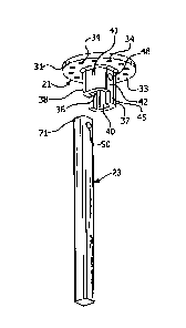
requires additional assistance from the installer.
[0004] An axial end 15 of the drive tool 14 is substantially planar, i.e., the
entirety
of the axial end 15 is equidistant from a flange 16 of the drive tool 14,
thereby
creating a possible pinch point between the axial end 15 of the drive tool 14
and an
axial end 17 of the helical pile 11 during alignment and insertion of the
helical pile
11. The installer's fingers can be pinched between the axial ends of the drive
tool and
helical pile when aligning the helical pile 11 with the drive tool 14 and
inserting the
helical pile in the drive tool socket 18. Accordingly, a need exists for
easily, quickly
and safely connecting the helical pile to the drive tool.
[0005] Similar problems exist when aligning and connecting an extension
member between the drive tool 14 and the helical pile 11. Extension members
are
connected between the drive tool 14 and the helical pile 11 to increase the
overall
length of a helical pile assembly. Accordingly, a need exists for quickly and
safely
connecting an extension member between a drive tool and an helical pile.
- 3 -
SUMMARY OF THE INVENTION
[0006] Accordingly, the present invention primarily seeks to provide an
improved
drive tool for connecting a helical pile thereto.
[0007] A further aspect of the present invention is to provide an improved
drive
tool having a portion of a wall extending axially further than a remaining
portion of
the wall to facilitate aligning a helical pile with the drive tool.
[0008] A further aspect of the present invention is to provide an improved
extension member for connecting a helical pile thereto.
[0009] A further aspect of the present invention is to provide an improved
extension member having a portion of a wall extending axially further than a
remaining portion of the wall to facilitate aligning a helical pile with the
extension
member.
[0010] The foregoing aspects are basically attained by a drive tool for
connecting
a member to the drive tool of a drive tool assembly. The drive tool includes a
flange
connectable to the drive tool assembly. A wall having a first portion extends
axially
outwardly from the flange and defines a socket for receiving a first member.
The wall
has a second portion extending axially from the first portion of the wall and
having a
circumferential extent less than the first portion to facilitate receiving the
first member
by providing a laterally and axially open alignment opening. The axially
extending
portion of the wall allows the first member to be quickly and safely aligned
with and
inserted in the socket of the drive tool.
[0011] The foregoing aspects are also basically attained by an extension
member
for connecting a helical pile to a drive tool. The extension member has a body
having
first and second ends. The first end of the extension member is connectable to
the
drive tool. A socket having a first portion is formed at the second end of the
body of
the extension member and is connectable to the helical pile. A second portion
of the
socket extends axially from the first portion and has a circumferential extent
less than
the first portion to facilitate receiving the helical pile by providing a
laterally and
axially open alignment opening.
CA 2863304 2019-03-20
- 4 -
[0012] The foregoing aspects are also basically attained by a method of
connecting a member to a drive tool. A first member is abutted against an
axially
extending portion of the drive tool. The axially extending portion has a
circumferential extent less than a socket portion from which the axially
extending
portion extends. The first member is inserted in the socket portion of the
drive tool.
A locking member secures the first member to the drive tool. The first member
can
have an axially extending portion to facilitate connecting a second member to
the first
member.
10012A1 A broad aspect of the invention pertains to a drive tool of
a drive tool
assembly, comprising a flange, and a wall having a first portion extending
along a
longitudinal axis away from a surface of the flange and defming a socket for
receiving
a member. The wall has a second portion extending along the longitudinal axis
away
from the first portion of the wall. The second portion has a peripheral extent
less than
a peripheral extent of the first portion to facilitate receiving the member by
providing
a laterally and axially open aligrunent opening.
[0012B] Another broad aspect comprehends an extension member for
connecting a helical pile to a drive tool having a longitudinal axis,
comprising a body
having first and second ends, the first end being connectable to the drive
tool. A
socket has a first portion formed at the second end of the body connectable to
the
helical pile. A second portion of the socket extends axially from the first
portion and
has a peripheral extent less than a peripheral extent of the first portion
thereof to
facilitate receiving the helical pile by providing a laterally and axially
open alignment
opening.
[0012C] Further still, the invention relates to a method of
connecting a member
to a drive tool, comprising the steps of abutting a first member against an
axially
extending portion of the drive tool by lateral movement of the first member
with
respect to the drive tool, the axially extending portion having a peripheral
extent less
than a peripheral extent of a socket portion from which the axially extending
portion
CA 2863304 2019-03-20
- 4a -
extend. The first member is inserted in the socket portion of the drive tool
by relative
movement of the first member with respect to the drive tool along a
longitudinal axis.
The first member is locked with respect to the drive tool.
[0013] Other aspects, advantages and salient features of the invention will
become
apparent from the following detailed description, which, taken in conjunction
with the
annexed drawings, discloses a preferred embodiment of the invention.
[0014] As used in this application, the terms "front," "rear," "upper,"
"lower,"
"upwardly," "downwardly," and other orientational descriptors are intended to
facilitate the description, and are not intended to limit the described
structure to any
particular position or orientation.
BRIEF DESCRIPTION OF THE DRAWINGS
[0015] The above aspects and features of the present invention will be more
apparent from the description for exemplary embodiments of the present
invention
taken with reference to the accompanying drawing figures, in which:
[0016] FIG. 1 is a perspective view of a conventional drive tool prior to
connecting a square helical pile thereto;
[0017] FIG. 2 is a perspective of a drive tool in accordance with an exemplary
embodiment of the present invention prior to connecting a square helical pile
thereto;
[0018] FIG. 3 is a perspective view of the drive tool of FIG. 2 prior to
connecting
an extension shaft, extension member and square helical pile thereto;
[0019] FIG. 4 is a perspective view of the drive tool of FIG. 2 prior to
connecting
the square helical pile thereto;
[0020] FIG. 5 is a rear elevational view of the drive tool and helical pile of
FIG. 4;
CA 2863304 2019-03-20
CA 02863304 2014-07-09
WO 2013/109426
PCT/US2013/020508
- 5 -
[0021] FIG. 6 is a side elevational view of the drive tool and helical pile of
FIG.
4;
[0022] FIG. 7 is a perspective view of the drive tool of FIG. 2 in which the
drive
tool is lowered to the square helical pile;
[0023] FIG. 8 is a rear elevational view of the drive tool and helical pile of
FIG. 7;
[0024] FIG. 9 is a side elevational view of the drive tool and helical pile of
FIG.
7;
[0025] FIG. 10 is a perspective view of the drive tool of FIG. 2 in which the
square helical pile is pressed against a surface of the alignment window;
[0026] FIG. 11 is a rear elevational view of the drive tool and helical pile
of FIG.
10;
[0027] FIG. 12 is a side elevational view of the drive tool and helical pile
of FIG.
10;
[0028] FIG. 13 is a perspective view of the drive tool of FIG. 2 in which the
square helical pile is fully inserted in the drive tool;
[0029] FIG. 14 is a rear elevational view of the drive tool and helical pile
of FIG.
13;
[0030] FIG. 15 is a side elevational view of the drive tool and helical pile
of FIG.
13;
[0031] FIG. 16 is a side elevational view of an extension member for a
circular
helical pile in accordance with another exemplary embodiment of the present
invention;
[0032] FIG. 17 is a bottom plan view in cross section of the extension member
of
FIG. 16;
[0033] FIG. 18 is a perspective view of the extension member of FIG. 16;
[0034] FIG. 19 is a side elevational view of an extension member for a square
helical pile having a substantially planar alignment window in accordance with
another exemplary embodiment of the present invention;
[0035] FIG. 20 is a bottom plan view in cross section of the extension member
of
FIG. 19;
CA 02863304 2014-07-09
WO 2013/109426
PCT/US2013/020508
- 6 -
[0036] FIG. 21 is a perspective view of the extension member of FIG. 19;
[0037] FIG. 22 is a side elevational view of the extension member of FIG. 3;
[0038] FIG. 23 is a bottom plan view in cross section of the extension member
of
FIG. 22;
[0039] FIG. 24 is a perspective view of the extension member of FIG. 22;
[0040] FIG. 25 is a side elevational view of an extension member for a square
helical pile having a substantially L-shaped alignment window in accordance
with
another exemplary embodiment of the present invention;
[0041] FIG. 26 is a bottom plan view in cross section of the extension member
of
FIG. 25;
[0042] FIG. 27 is a perspective view of the extension member of FIG. 25;
[0043] FIG. 28 is a side elevational view of a drive tool in accordance with
another exemplary embodiment of the present invention;
[0044] FIG. 29 is a front elevational view of the drive tool of FIG. 28; and
[0045] FIG. 30 is a front elevational view in cross section of the drive tool
taken
along line 30-30 of FIG. 28.
[0046] Throughout the drawings, like reference numerals will he understood to
refer to like parts, components and structures.
DETAILED DESCRIPTION OF EXEMPLARY EMBODIMENTS
[0047] As shown in FIGS. 2 ¨ 30, exemplary embodiments of the present
invention includes a drive tool 21 of a drive assembly 22 for connecting a
helical pile
23 thereto. The drive assembly 22 includes the drive tool 21, a torque
indicator 24, a
Kelly bar adapter 25 and a Kelly bar 26, as shown in FIGS. 2 and 3. The torque
indicator 24 is optional, such that the drive tool 21 can be directly
connected to the
Kelly bar adapter 25.
[0048] The Kelly bar 26 is connected to a powered drive head (not shown) for
transferring torque to the helical pi1e23 to be installed. The Kelly bar 26 is
inserted
in a socket 27 of the Kelly bar adapter 25 and secured thereto by a locking
member.
The Kelly bar adapter 25 has a flange 28 that can be connected either to the
torque
- 7 -
indicator 24 or the drive tool 21. A conventional bent arm pin and coil can be
used to
secure the Kelly bar 26 to the Kelly bar adapter 25.
[0049] The torque indicator 24 includes an upper flange 29 connectable to the
Kelly bar adapter flange 28 and a lower flange 30 connectable to the drive
tool 21.
The torque indicator 24 monitors torque during installation of the helical
pile 23 such
that torque ratings are not exceeded.
[0050] The drive tool 21 has a flange 31 having upper and lower surfaces 32
and
33, as shown in FIGS. 2 ¨6. The flange 31 has a plurality of openings 34 for
aligning
with corresponding openings in either the Kelly bar adapter flange 28 or the
torque
indicator lower flange 30. The flange openings 34 extend from the upper
surface 32
to the lower surface 33 of the flange 31. Fasteners inserted through the
aligned
openings secure the drive tool to the torque indicator 24 or the Kelly bar
adapter 25.
[0051] A wall 35 extends downwardly from the flange 31 of the drive tool 21,
as
shown in FIGS. 2 ¨ 15. The wall 35 defines a socket 36 for receiving an anchor
shaft
23. A second portion 37 of the wall 35 extends axially from a first portion 38
of the
wall. The first portion 38 of the wall 35 extends from the lower surface 33 of
the
flange 31. The second portion 37 extends axially from an end 39 of the first
portion
38 of the wall 35. The second portion 37 of the wall 35 has a circumferential
or
peripheral extent less than that of the first portion 38 to facilitate
aligning the anchor
shaft 23 with the drive tool 21 and inserting the anchor shaft in the socket
36 by
providing a laterally and axially open alignment opening.
[0052] As shown in FIGS. 2 ¨ 15, the wall 35 has a substantially square cross
section transverse to the longitudinal axis of the drive assembly 22 and
helical pi1e23
to define a substantially square socket 36. The wall 35 and socket 36 may be
any
shape suitable to receive the helical pile 23. As the helical pile 23 has a
substantially
square cross section, the socket 36 has a substantially square cross section.
The wall
35 has first, second, third and fourth sides 41 ¨44, as shown in FIGS. 4 ¨ 6.
To
receive a circular helical pile, a socket having a substantially circular
cross section
transverse to a longitudinal axis is used.
CA 2863304 2019-03-20
CA 02863304 2014-07-09
WO 2013/109426
PCT/US2013/020508
- 8 -
[0053] As shown in FIGS. 2 ¨ 15, the second portion 37 of the wall 35 is
substantially C-shaped when viewed from a longitudinal end of the drive tool
21, as
shown in FIG. 4. Although shown as being substantially C-shaped in FIGS. 2 ¨
15,
the second portion of the wall can have any suitable shape as shown in FIGS.
17 ¨ 27.
The second portion 37 has first, second and third sides 45 ¨ 47, as shown in
FIGS. 4 ¨
6. The second side 46 of the second portion 37 extends axially downwardly from
the
third side 43, as shown in FIG. 5. The width of the second side 46 of the
second
portion 37 is substantially similar to the width of the third side 41 of the
first portion
38. The widths of the first and third sides 45 and 47 are smaller than the
widths of the
second and fourth sides 42 and 44 of the first portion 38 of the wall 35, as
shown in
FIGS. 4 and 6. The second portion 37 of the wall 35, as shown in FIG. 4, forms
an
alignment window to facilitate aligning the helical pile 23 with the drive
tool 21 and
inserting the helical pile in the socket 35.
[0054] Openings 48 and 49 in the second and fourth sides 42 and 44,
respectively,
align with openings 50 and 51 in the helical pile 23 to receive a locking
member to
secure the helical pile to the drive tool 21. As shown in FIG. 2, the locking
member
can be a conventional bent arm pin 52 having a coil 53 at an end thereof to
prevent
accidental removal of the pin from the aligned openings.
[0055] Alternatively, as shown in FIGS. 28 ¨ 30, a drive tool 121 according to
another exemplary embodiment of the present invention has a conventional
locking
dog 151 as the locking member. The drive tool 121 of the second exemplary
embodiment is substantially similar to the drive tool 21 of the first
exemplary
embodiment and similar features are indicated by reference numerals "Ixx".
Oppositely disposed protrusions 152 and 153 extend outwardly from opposite
sides of
a wall 135 of the drive tool 121. Although shown with a locking dog 151
disposed in
only the first protrusion 152, a second locking dog can be disposed in the
second
protrusion 153. The protrusions 152 and 153 are shown disposed approximately
180
degrees apart, but any suitable configuration can be used, such as disposed
the
protrusions 90 degrees apart.
CA 02863304 2014-07-09
WO 2013/109426
PCT/US2013/020508
- 9 -
[0056] A locking pin 154 is axially and rotatably movable within the locking
dog
151. Preferably, the locking pin 154 is substantially perpendicular to a
longitudinal
axis of the drive tool socket 136. The locking pin 154 is movable between an
insertion position and a locking position. A spring member (not shown) biases
the
locking pin 154 toward the locking position, as shown in FIG. 30, in which a
free end
155 of the locking pin 154 extends into the socket 136. In the insertion
position, the
locking pin154 is moved out of the socket 136 to allow insertion of the
helical pile 23.
[0057] The free end 155 of the locking pin 154 has a sloped surface 156. The
sloped surface 156 extends upwardly and radially into the socket 136 to allow
the
helical pile 23 to pass the locking pin 154 during insertion of the helical
pile into the
socket. An upper surface 157 of the locking pin 154 prevents an installed
helical pile
23 from moving the locking pin and accidentally removing the helical pile from
the
drive tool 121. An opening 158 in a housing 159 of the locking dog receives a
set
screw (not shown) to further prevent movement of the locking dog 151 when
connected to the drive tool 121.
[0058] An extension member 54, as shown in FIGS. 3. and 22 ¨ 24, can he used
to
extend the length that the helical pile 23 can be screwed in the ground. The
extension
member 54 is connected between the drive tool 21 and helical pile 23. Any
suitable
number of extension members 54 can be used to obtain the desired length. The
extension member 54 has a body 55 having a first end 56 and a second end 57.
The
first end 56 is received by the socket 35 of the drive tool 21. The second end
56 of
the extension member 54 has a socket member 58 connected thereto to receive
the
helical pile 23 or another extension member. Preferably, the extension member
54 is
unitarily formed as a single piece. Alternatively, the socket member 58 can be
welded
to the extension member 54. A first opening 63 is formed proximal the first
end 56 of
the extension member and a second opening 64 is formed proximal the second end
57.
The first opening 63 is aligned with the openings 48 and 49 in the drive tool
to receive
a locking member. The second opening 64 in the extension member 54 is aligned
with the openings 50 and 51 in the helical pile 23 (or openings in another
extension
member) to receive a locking member. Any suitable locking member can be used,
CA 02863304 2014-07-09
WO 2013/109426
PCT/US2013/020508
- 10 -
such as, but not limited to, the bent arm pin 52 and coil 53, a fastener and
nut, or a
locking dog 151 (FIGS. 28 ¨ 30). The extension member 54 is preferably made of
steel, although any suitable material can be used.
[0059] The socket member 57 has an alignment window foliated substantially
similarly to the alignment window of the drive tool 21. A first portion 61 of
a wall 59
extends axially downwardly from the second end 57 to form a socket 60. A
second
portion 62 of the wall 59 extends axially from the first portion 61 of the
wall 59 and
has a circumferential extent less than the first portion to form the alignment
window
to facilitate connecting the helical pile 23 or another extension member 54
thereto by
providing a laterally and axially open alignment opening.
[0060] Alternative embodiments of the extension member are shown in FIGS. 16
¨ 21 and 25 ¨ 28. Although such configurations are described with respect to
an
extension member, such alternative configurations can also be used with the
drive
tool.
[0061] As shown in FIGS. 16 ¨ 18, a round extension member 254 has a socket
member 258 defining a substantially circular socket 260. A second portion 262
extends axially further than a first portion 261 of a wall 259 to form an
alignment
window. The second portion 262 has a substantially semi-circular cross section
and
extends approximately 180 degrees, although the second portion 262 can extend
any
suitable amount to form the alignment window.
[0062] As shown in FIGS. 19 ¨ 21, an extension member 354 has a socket
member 358 defining a substantially square socket 360. A second portion 362
extends axially further than a first portion 361 of a wall 359 to form an
alignment
window. The second portion 362 extends from only one side of the first portion
361
of the wall 359 such that the second portion 362 is substantially planar.
[0063] As shown in FIGS. 25 ¨ 27, an extension member 454 has a socket
member 458 defining a substantially square socket 460. A second portion 462
extends axially further than a first portion 461 of a wall 459 to form an
alignment
window. The second portion 462 has a substantially L-shaped cross section.
Each leg
CA 02863304 2014-07-09
WO 2013/109426
PCT/US2013/020508
- 1 1 -
of the second portion 462 has a width less than that of the side of the first
portion 461
from which it extends.
[0064] The drive tools 21 and 121 of the first and second exemplary
embodiments
are preferably made of steel, although any suitable material can be used. The
drive
tools 21 and 121 are preferably unitarily formed as a single piece.
Assembly and Operation
[0065] The alignment window in accordance with exemplary embodiments of the
present invention provides a quick, easy and safe connection between the
helical pile
23, drive tool 21 and extension member 54. The alignment window allows the
helical
pile 23 to be safely aligned with the drive tool 21 prior to insertion of the
helical pile,
thereby reducing the likelihood of injury to the installer. The exemplary
embodiments of the present invention eliminates the difficulty and likelihood
of
injury associated with bringing two substantially planar ends together, by
providing
one of the members with an axially extending portion.
[0066] As shown in FIGS. 4 ¨ 9, the drive tool 21, which is connected to the
drive
assembly 22 (FIG. 2) is lowered to a position proximal the helical pile 23. An
upper
end 71 of the helical pile 23 is then brought into alignment with the drive
tool 23.
The helical pile 23 is pushed into the alignment window such that the upper
end 71 of
the helical pile 23 engages an inner surface 40 of the second portion 38 of
the drive
tool 21, as shown in FIGS. 10 ¨ 12. Because both the drive tool 21 and the
helical
pile 23 do not have substantially planar ends, the pinch point between the
drive tool
and the helical pile is substantially eliminated. The axially extending second
portion
38, which also has a circumferential extent less than the first portion, of
the drive tool
21 acts as a guide to facilitate alignment and insertion of the helical pile
23 with the
drive tool 21 and substantially eliminates the pinch points therebetween.
[0067] After pressing the upper end 71 of the helical pile 23 against the
inner
surface 40 of the second portion 38 of the drive tool 21 to align the helical
pile with
the drive tool 21, the drive tool 21 is lowered onto the helical pile 23 to
fully engage
the two members as shown in FIGS. 13 ¨ 15. The openings 50 and 51 (FIGS. 4 and
CA 02863304 2014-07-09
WO 2013/109426
PCT/US2013/020508
- 12 -
6) proximal the upper end 71 of the helical pile 23 are now aligned with the
openings
48 and 49 of the drive tool 21 such that a locking member can secure the
helical pile
to the drive tool. As shown in FIG. 2, the bent arm pin 52 and coil 53 can be
used to
secure the helical pile 23 to the drive tool 21. Alternatively, the locking
dog 151
(FIGS. 28 ¨ 30) can be used to secure the helical pile 23 to the drive tool
21.
[0068] A similar procedure is used to connect an extension member 54 between
the drive tool 21 and the helical pile 23, as shown in FIG. 3. The extension
member
has the second portion 62 extending axially further than the first portion 61
of the wall
59 to provide the extension member with an alignment window to easily, quickly
and
safely align and connect the helical pile 23 or another extension member.
[0069] While an advantageous embodiment has been chosen to illustrate the
invention, it will be understood by those skilled in the art that various
changes and
modifications may be made therein without departing from the scope of the
invention
as defined in the appended claims.