Language selection

Search

Patent 2863917 Summary

Third-party information liability

Some of the information on this Web page has been provided by external sources. The Government of Canada is not responsible for the accuracy, reliability or currency of the information supplied by external sources. Users wishing to rely upon this information should consult directly with the source of the information. Content provided by external sources is not subject to official languages, privacy and accessibility requirements.

Claims and Abstract availability

Any discrepancies in the text and image of the Claims and Abstract are due to differing posting times. Text of the Claims and Abstract are posted:

  • At the time the application is open to public inspection;
  • At the time of issue of the patent (grant).
(12) Patent Application: (11) CA 2863917
(54) English Title: RAIL VEHICLE COMPRISING A FROST-PROTECTED WATER OUTLET PIPE
(54) French Title: VEHICULE FERROVIAIRE MUNI D'UNE CONDUITE D'EVACUATION DES EAUX PROTEGEE CONTRE LE GEL
Status: Deemed Abandoned and Beyond the Period of Reinstatement - Pending Response to Notice of Disregarded Communication
Bibliographic Data
(51) International Patent Classification (IPC):
  • B61D 35/00 (2006.01)
(72) Inventors :
  • FROESE, JURGEN (Germany)
  • KOHNEN, HEINRICH (Germany)
  • ROHLOF, CHRISTOF (Germany)
(73) Owners :
  • SIEMENS AKTIENGESELLSCHAFT
(71) Applicants :
  • SIEMENS AKTIENGESELLSCHAFT (Germany)
(74) Agent: SMART & BIGGAR LP
(74) Associate agent:
(45) Issued:
(86) PCT Filing Date: 2013-01-11
(87) Open to Public Inspection: 2013-08-15
Availability of licence: N/A
Dedicated to the Public: N/A
(25) Language of filing: English

Patent Cooperation Treaty (PCT): Yes
(86) PCT Filing Number: PCT/EP2013/050436
(87) International Publication Number: EP2013050436
(85) National Entry: 2014-08-06

(30) Application Priority Data:
Application No. Country/Territory Date
10 2012 201 851.4 (Germany) 2012-02-08

Abstracts

English Abstract

The invention relates to a rail vehicle comprising a water outlet pipe (1), the end piece (2) of which is connected to an opening (4) in a floor plate (5) of the rail vehicle, wherein at the end piece (2) a heated plate (7) is provided that is parallel to the floor plate (5) and that comprises an opening (8) that is adapted to a free cross-section of the end piece (2) of the water outlet pipe (1).


French Abstract

L'invention concerne un véhicule ferroviaire muni d'une conduite d'évacuation des eaux (1) dont l'embout (2) est adjacent à une ouverture (4) ménagée dans un panneau de plancher (5) du véhicule ferroviaire, un panneau chauffé (7) prévu au niveau de l'embout (2) étant disposé parallèlement au panneau de plancher (5) et comportant un passage (8) qui est adapté à une section transversale libre de l'embout (2) de la conduite d'évacuation des eaux (1).

Claims

Note: Claims are shown in the official language in which they were submitted.

- 5 -
Claims
1. A rail vehicle comprising a water outlet pipe (1), the end
piece (2) of which is connected to an opening (4) in a floor
plate (5) of the rail vehicle,
characterized in that
a heated plate (7) is provided at the end piece (2), is
arranged parallel to the floor plate (5) and has an aperture
(8) which is adapted to a free cross section of the end piece
(2) of the water outlet pipe (1).
2. The rail vehicle as claimed in claim 1,
characterized in that
the heated plate (7) is designed as a flat round plate.
3. The rail vehicle as claimed in either of claims 1 and 2,
characterized in that
the heated plate (7) encloses the end piece (2) of the water
outlet pipe (1).
4. The rail vehicle as claimed in one of claims 1 to 3,
characterized in that
an areally acting heating device is provided on the side of the
heated plate (7) which is opposite to the floor plate (5).
5. The rail vehicle as claimed in claim 4,
characterized in that
the areally acting heating device for the heated plate is
designed as a heating mat (11).

-6-
6. The rail vehicle as claimed in one of claims 1 to 5,
characterized in that
a circumferential surface of the end piece (2) of the water
outlet pipe (1) is provided with an areally acting heating
device.
7. The rail vehicle as claimed in claim 6,
characterized in that
the areally heating device for the end piece (2) of the water
outlet pipe (1) is designed as a heating mat (12).
8. The rail vehicle as claimed in one of claims 1 to 7,
characterized in that
the heated plate (7) has two partial plates (9, 10) lying over
one another, of which the partial plate (9) remote from the
floor plate (5) is heated and the partial plate (10) situated
closer to the floor plate (5) is designed as a heat-conducting
plastic plate.
9. The rail vehicle as claimed in one of claims 1 to 8,
characterized in that
a free cross section of the aperture (8) in the heated plate
(7) increases in the direction of the floor plate (5).
10. The rail vehicle as claimed in one of claims 1 to 9,
characterized in that
a free cross section of the opening (4) in the floor plate (5)
is larger than a free cross section of the aperture (8) in the
heated plate (7).
11. The rail vehicle as claimed in claim 10,
characterized in that

-6a-
a free cross section of the opening (4) in the floor plate (5)
corresponds to at least 1.5 times the free cross section of the
aperture (8) in the heated plate (7).

Description

Note: Descriptions are shown in the official language in which they were submitted.


CA 02863917 2014-08-06µ
PCT/EP2013/050436 - 1 -
2012P02059W0US
Description
Rail vehicle comprising a frost-protected water outlet pipe
The invention relates to a rail vehicle comprising a water
outlet pipe, the end piece of which is connected to an opening
in a floor plate of the rail vehicle.
Water outlet pipes of this type are designed to be heated
particularly in the region of their end piece such that, when
low temperatures occur, freezing over of the water outlet pipe
at their outlet point is reliably avoided. Such a heating
device is frequently present as a heating tape which is wound
around the water outlet pipe. In principle, in the case of rail
vehicles, all the water pipes, which are laid under the floor,
are equipped with heating tapes.
Gray water, for example, which occurs in the galley region of
the rail vehicle during normal operation of a water system,
must be guided away to a track bed. Such a gray-water outlet
pipe or drainage pipe terminates with the feed-through through
a floor plate of the rail vehicle. In the event that the outlet
point of the gray-water drainage pipe freezes over, gray water
which occurs can no longer be guided away and can accumulate in
the galley.
Taking this as a starting point, the object on which the
invention is based is to further develop the rail vehicle
mentioned at the outset in such a way that increased frost
protection is achieved for the outlet point of the water outlet
pipe.
This object is achieved in that a heated plate is provided at
the end piece of the water outlet pipe, is arranged parallel to

CA 02863917 2014-08-06
,
PCT/EP2013/050436 - 2 -
2012P02059WOUS
the floor plate and has an aperture which is adapted to a free
cross section of the end piece of the water outlet pipe.
The heated plate thus provides an effective heat source at the
outlet point of the water outlet pipe, this heat source
effectively preventing freezing over of the end piece of the
water outlet pipe even at low temperatures.
The heated plate is preferably designed as a flat round plate.
The heated plate can enclose the end piece of the water outlet
pipe such that there is thermal contact between the heated
plate and the end piece.
It is advantageous if an areally acting heating device, which
can be designed in particular as a heating mat, is provided on
the side of the heated plate which is opposite to the floor
plate. In this way, effective heating of the plate takes place.
Moreover, a circumferential surface of the end piece of the
water outlet pipe can be provided with an areally acting
heating device which likewise can again be designed as a
heating mat. Both the heating device for the end piece and the
heating device for the heated plate can have a common
electrical power supply.
The heated plate can have two partial plates lying over one
another, of which the partial plate remote from the floor plate
is heated and the partial plate which is situated closer to the
floor plate is designed as a heat-conducting plastic plate.
This design has the advantage that, while maintaining the
heated partial plate, an overall height of the heated plate can
be varied by adapting a height of the plastic plate.

CA 02863917 2014-08-06
PCT/EP2013/050436 - 3 -
2012P02059WOUS
Preferably, a free cross section of the aperture in the heated
plate increases in the direction of the floor plate. This
increase can be constant or stepwise. This design assists frost
protection at the water outlet.
It is advantageous if a free cross section of the opening in
the floor plate is larger than a free cross section of the
aperture in the heated plate. In this case, part of the surface
of the heated plate which faces the floor plate is exposed and
can counteract freezing over in the region of the end piece of
the water outlet pipe.
Preferably, for example with a cylindrically symmetrical design
of the end piece of the water outlet pipe, of the heated plate
and of the opening in the floor plate, a free cross section of
the opening in the floor plate corresponds to at least 1.5
times the free cross section of the aperture in the heated
plate. In this way, a considerable part of the surface of the
heated plate is exposed.
An exemplary embodiment of the invention will be explained in
even more detail below with reference to the drawing.
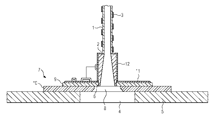
The single figure shows a cross-sectional representation of an
end region of a water outlet pipe shown together with a portion
of a floor plate of a rail vehicle.
The figure shows a water outlet pipe 1 coming, for example,
from a galley of a rail vehicle and having an end piece 2
which, in the present exemplary embodiment, is provided as a
separate component. It is also conceivable that the water
outlet pipe 1 maintains its external shape as far as the lower
edge, as seen in the figure, of the end piece 2.

CA 02863917 2014-08-06
PCT/EP2013/050436 - 3a -
2012P02059W0US
Outside the end piece 2, a heating tape 3 is wound around the
water outlet pipe 1 for protection against the effects of
frost.

CA 02863917 2014-08-06
PCT/EP2013/050436 - 4 -
2012P02059W0US
The end piece 2 of the water outlet pipe 1 is connected to an
opening 4 in a floor plate 5 of the rail vehicle.
A floor plate-side edge 6 of the end piece 2 is enclosed by a
heated plate 7 which has a central aperture 8 which is adapted
to a free cross section of the end piece 2 in the region of the
edge 6. The plate 7 is arranged parallel to the floor plate 5
and constructed from two partial plates 9, 10 arranged over one
another. Here, the partial plate 9 remote from the floor plate
is embodied as a metallic disk plate, whereas the partial
plate 10 arranged between the disk plate 9 and the floor plate
5 is produced from a heat-conducting plastic, for example from
Vulkollan . Whereas the partial plate 9 encloses the edge 6 of
the end piece 2, the partial plate 10 shows a free cross
section which increases in the direction of the floor plate 5.
This free cross section is in turn dimensioned to be smaller
than that of the opening 4 in the floor plate 5.
It should be emphasized that the described arrangement is
embodied to be generally cylindrically symmetrical. In this
respect, a diameter of the opening 4 in the floor plate 5
exceeds the maximum diameter of the aperture 8 in the plate 7
such that a surface region of the partial plate 10 which faces
the floor plate 5 is exposed. A heating mat 11 is arranged on
the partial plate 9 and provides a large-area heating of the
plate 7 overall. In this way, favorable frost protection for
the water outlet pipe 1, in particular in the region of its
outlet point, is achieved.
The end piece 2 is also provided at its circumference with a
heating mat 12 which, together with the heating mat 11, can be
supplied with electrical power.

Representative Drawing
A single figure which represents the drawing illustrating the invention.
Administrative Status

2024-08-01:As part of the Next Generation Patents (NGP) transition, the Canadian Patents Database (CPD) now contains a more detailed Event History, which replicates the Event Log of our new back-office solution.

Please note that "Inactive:" events refers to events no longer in use in our new back-office solution.

For a clearer understanding of the status of the application/patent presented on this page, the site Disclaimer , as well as the definitions for Patent , Event History , Maintenance Fee  and Payment History  should be consulted.

Event History

Description Date
Time Limit for Reversal Expired 2017-01-11
Application Not Reinstated by Deadline 2017-01-11
Deemed Abandoned - Failure to Respond to Maintenance Fee Notice 2016-01-11
Change of Address or Method of Correspondence Request Received 2015-01-15
Inactive: Cover page published 2014-10-31
Inactive: IPC removed 2014-10-10
Inactive: First IPC assigned 2014-10-10
Inactive: Notice - National entry - No RFE 2014-09-23
Application Received - PCT 2014-09-23
Inactive: First IPC assigned 2014-09-23
Inactive: IPC assigned 2014-09-23
Amendment Received - Voluntary Amendment 2014-09-16
National Entry Requirements Determined Compliant 2014-08-06
Application Published (Open to Public Inspection) 2013-08-15

Abandonment History

Abandonment Date Reason Reinstatement Date
2016-01-11

Maintenance Fee

The last payment was received on 2014-12-08

Note : If the full payment has not been received on or before the date indicated, a further fee may be required which may be one of the following

  • the reinstatement fee;
  • the late payment fee; or
  • additional fee to reverse deemed expiry.

Patent fees are adjusted on the 1st of January every year. The amounts above are the current amounts if received by December 31 of the current year.
Please refer to the CIPO Patent Fees web page to see all current fee amounts.

Fee History

Fee Type Anniversary Year Due Date Paid Date
Basic national fee - standard 2014-06-06
MF (application, 2nd anniv.) - standard 02 2015-01-12 2014-12-08
Owners on Record

Note: Records showing the ownership history in alphabetical order.

Current Owners on Record
SIEMENS AKTIENGESELLSCHAFT
Past Owners on Record
CHRISTOF ROHLOF
HEINRICH KOHNEN
JURGEN FROESE
Past Owners that do not appear in the "Owners on Record" listing will appear in other documentation within the application.
Documents

To view selected files, please enter reCAPTCHA code :


To view images, click a link in the Document Description column. To download the documents, select one or more checkboxes in the first column and then click the "Download Selected in PDF format (Zip Archive)" or the "Download Selected as Single PDF" button.

List of published and non-published patent-specific documents on the CPD .

If you have any difficulty accessing content, you can call the Client Service Centre at 1-866-997-1936 or send them an e-mail at CIPO Client Service Centre.


Document
Description 
Date
(yyyy-mm-dd) 
Number of pages   Size of Image (KB) 
Drawings 2014-08-05 1 14
Description 2014-08-05 5 157
Representative drawing 2014-08-05 1 11
Claims 2014-08-05 3 59
Abstract 2014-08-05 1 10
Reminder of maintenance fee due 2014-09-22 1 111
Notice of National Entry 2014-09-22 1 193
Courtesy - Abandonment Letter (Maintenance Fee) 2016-02-21 1 173
PCT 2014-08-05 3 121
Correspondence 2015-01-14 2 65