Note: Descriptions are shown in the official language in which they were submitted.
CA 02863945 2014-09-17
Attorney Ref: 1147P053CA01
AN ANTI-RATTLE DEVICE WITH HITCH COVER
Field of the Invention
The present invention relates generally to an anti-rattle device, and more
specifically
to an anti-rattle device with a hitch cover operatively engaging a receiver
hitch with
a draw bar and reducing rattle therebetween.
Background
Many vehicles are equipped with rear or front mounted receiver hitches used
for towing of vehicles and as an attachment point for many other cargo
accessories.
These types of receiver hitches typically include a receiver opening or cavity
used
for the receipt of a draw bar. The receiver opening comes in various sizes
depending
upon the towing capabilities thereof. For example, receiver-type trailer hitch
assemblies are typically offered with a generally square receiver opening of
1.25
inches (32 mm) for Class I/II, 2 inches (51 mm) for Class III/IV/V, and some
Class
V hitches are available in 2.5 inches (64 mm) opening sizes.
A draw bar having a shank includes outer dimensions slightly smaller than
the internal dimensions of the receiver opening and is normally slidable
within the
receiver opening. The draw bar is typically connected to the receiver opening
by a
pin inserted through the two tubular portions thereof and locked or clipped to
prevent removal of the draw bar from the receiver hitch. The two components
are
both toleranced to ensure that the draw bar can be freely inserted and removed
from
the receiver opening.
The draw bar may include a standard ball-mount for engaging with the
coupler of a towed vehicle or other wheeled vehicle. Another popular use for
receiver hitches is the use as a coupling device for installing cargo
accessory such as
equipment racks onto the vehicle. Bicycle earlier racks, ski carriers, storage
boxes
and other types of carriers have been designed to use the above-described draw
bar
to engage within a receiver opening. This provides a universal system that
allows a
vehicle operator to use various towed vehicles and accessory carriers with a
single
coupling system.
1
CA 02863945 2014-09-17
Attorney Ref: 1147P053CA01
A particular problem with the use of these receiver hitches is the clearance
between the internal dimensions of the receiver opening and the external
dimensions
of the draw bar. The tubular portions thereof by necessity must have
sufficient
clearance to be able to be easily telescoped together. However, this clearance
between the two tubular portions allows relative movement between them. The
draw
bar tends to rattle or chatter within the receiver opening during use. This
rattle or
chatter can be a distraction to the driver and can cause premature wear to the
components.
A need is therefore identified for an improved apparatus whereby the
movement between the receiver hitch and the draw bar is minimized when they
are
operatively secured together. Further, there is a need for an anti-rattle
apparatus that
is easy to operate and is effective. Further still, there is a need for an
anti-rattle
device with a cover for generally protecting the receiver opening of the
receiver
hitch when the draw bar is not attached thereto.
Summary of the Invention
An anti-rattle device is shown and described. The anti-rattle device may
include a frame configured to engage a receiver hitch and to receive a draw
bar. The
anti-rattle device may also include a cam engaging assembly operatively
engaged
with the frame, where the cam engaging assembly is selectively positionable
between disengaged and engaged positions whereby the cam engaging assembly is
adapted to engage the draw bar against the receiver hitch in the engaged
position.
A system may include a receiver hitch configured to be attached with a
vehicle, a draw bar telescopingly engaged with the receiver hitch, and an anti-
rattle
device engaged with the receiver hitch. The anti-rattle device may include a
frame
telescopingly engaging the receiver hitch, the frame having an opening
receiving the
draw bar. The anti-rattle device may also include a cam engaging assembly
operatively engaged with the frame, where the cam engaging assembly is
positionable between disengaged and engaged positions whereby the cam engaging
assembly engages the draw bar against the hitch receiver in the engaged
position.
An accessory mounting assembly configured to be selectively secured with a
receiver hitch may include a draw bar configured to telescopingly engage the
2
CA 02863945 2014-09-17
Attorney Ref: 1147P053CA01
receiver hitch, and an anti-rattle device. The anti-rattle device may include
a frame
having a cam aperture and an opening to receive the draw bar, and a cam lever
mount positionable within the cam aperture. The anti-rattle device may also
include
a plunger engaged with the cam lever mount and positionable relative to the
cam
lever mount, where the plunger is positionable between disengaged and engaged
positions whereby the plunger engages the draw bar against the receiver hitch
in the
engaged position.
An anti-rattle device may include a frame configured to engage a receiver
hitch and to receive a draw bar, an isolator configured to engage the receiver
hitch,
where the frame circumscribes the isolator and the isolator is configured to
dampen
movement between the draw bar and receiver hitch. The anti-rattle device may
also
include a cam lever operatively secured with the frame, the cam lever
positionable
between disengaged and engaged positions whereby at least a portion of the cam
lever is engageable with the receiver hitch deflecting the isolator between
the draw
bar and receiver hitch in the engaged position.
Brief Description of the Drawings
Operation of the invention may be better understood by reference to the
detailed description taken in connection with the following illustrations,
wherein:
Figure 1 is a perspective view of an anti-rattle device operatively engaged
with a receiver hitch attached to a vehicle
Figure 2 is a perspective view of embodiments of an anti-rattle device
operatively engaging a receiver hitch;
Figure 3 is a perspective view of embodiments of the anti-rattle device with
the cover in a closed position;
Figure 4 is a perspective view of the anti-rattle device operatively engaging
a
receiver hitch with a draw bar being telescoped in the receiver hitch;
Figure 5 is an exploded view of the anti-rattle device;
3
CA 02863945 2014-09-17
Attorney Ref: 1147P053CA01
Figure 6 is a front view of the anti-rattle device in a disengaged position on
the receiver hitch;
Figure 7 is a front view of the anti-rattle device in an engaged position on
the
receiver hitch;
Figure 8 is a front view embodiments of an anti-rattle device in a disengaged
position on the receiver hitch;
Figure 9 is a front view of embodiments of the anti-rattle device in an
engaged position on the receiver hitch;
Figure 10 is a front view of embodiments of an anti-rattle device in a
disengaged position on a receiver hitch;
Figure 11 is a front view of embodiments of the anti-rattle device in an
engaged position on the receiver hitch;
Figure 12 is a cross-sectional view of embodiments of an anti-rattle device in
a disengaged position on a receiver hitch;
Figure 13 is front a view of embodiments of the anti-rattle device in an
engaged position on the receiver hitch;
Figure 14 is a perspective view of embodiments of an anti-rattle device;
Figure 15 is a perspective view of embodiments of an anti-rattle device with
a cover having a 4-way flat holder operatively engaging a receiver hitch;
Figure 16 is a front view of embodiments of an anti-rattle device with a
cover in a closed position.
Figure 17 is a cross-sectional view of embodiments of an anti-rattle device in
an engaged position with a cover in a closed position.
Figure 18 is a cross-sectional view of embodiments of the anti-rattle device
of Figure 17 in a disengaged position with the cover in a closed position.
Figure 19 is an exploded view of embodiments of a cam lever.
4
CA 02863945 2014-09-17
Attorney Ref: 1147P 053 CA01
Figure 20 is an exploded view of embodiments of an anti-rattle device.
Detailed Description
Reference will now be made in detail to exemplary embodiments of the
present invention, examples of which are illustrated in the accompanying
drawings.
It is to be understood that other embodiments may be utilized and structural
and
functional changes may be made without departing from the respective scope of
the
invention. Moreover, features of the various embodiments may be combined or
altered without departing from the scope of the invention. As such, the
following
description is presented by way of illustration only and should not limit in
any way
the various alternatives and modifications that may be made to the illustrated
embodiments.
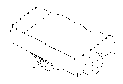
Reference is now made to Figure 1 illustrating exemplary embodiments of a
receiver hitch 20 that may be operatively attached with a vehicle 24 in any
appropriate manner. The receiver hitch 20 may be of any appropriate
configuration.
The present teachings are not limited to the receiver hitch 20 shown and
described
herein ¨ any current or newly developed receiver hitch may be utilized. The
receiver
hitch 20 may be attached to a frame (not shown) of the vehicle 24, such as
through
use of fasteners or the like. As illustrated the receiver hitch 20 may include
a
receiver tube 28 adapted to selectively accept a draw bar of an appropriate
shape and
size as described in more detail below.
The receiver tube 28 may be mounted to the receiver hitch 20 by any
appropriate mounting techniques, such as by way of non-limiting examples,
fastening or welding. In some embodiments, the receiver tube 28 may include a
generally square receiver opening 32 of approximately 1.25 inches (32 mm) for
Class I/II, 2 inches (51 mm) for Class III/IV/V, or 2.5 inches (64 mm) for
class V. It
is to be expressly understood that other sizes or shapes of the receiver tube
28 and
receiver opening 32 may be used without departing from the present teachings ¨
see
Figure 2.
The receiver tube 28 may include an interior portion 34 and an exterior
portion 36 ¨ the interior portion 34 may terminate at the receiver opening 32.
The
receiver tube 28 may also include at least two apertures 40 disposed from one
5
CA 02863945 2014-09-17
Attorney Ref: 1147P053CA01
another. By way of a non-limiting example, the apertures 40 may be generally
aligned ¨ such as axially aligned ¨ on opposing sides 44 of the receiver tube
28. The
apertures 40 may extend entirely through the sides 44 and may be configured to
receive a pin 41 of any appropriate configuration. In some embodiments, the
receiver tube 28 may include an additional set of apertures 40a disposed from
one
another. However, the present teachings are not limited to this configuration.
Any
appropriate number of apertures may be used without departing from the present
teachings.
A draw bar 48 of any appropriate configuration may be selectively engaged
with the receiver hitch 20 ¨ see Figure 4. The present teachings are not
limited to the
configuration shown and described. The draw bar 48 may include an exterior
portion
52 having a generally corresponding shape to that of the interior portion 34
of the
receiver tube 28. The draw bar 48 may also have an external size or shape
slightly
less than the internal size or shape of the receiver tube 28. This may enable
the draw
bar 48 to be inserted within the receiver tube 28 in a telescoping manner, as
shown
in Figure 4. By way of a non-limiting example, the difference in the
dimensions of
the interior portion 34 of the receiver tube 28 and the exterior portion 52 of
the draw
bar 48 may be about one-sixteenth of an inch ¨ although the teachings are not
limited to this dimension. This dimensional difference may allow the draw bar
48 to
be easily inserted or telescoped within the receiver tube 28. It should be
understood
that the term draw bar is used throughout to describe the portion that is
insertable
into the receiver tube 28 and is not limited to a ball mount. The term draw
bar as
used throughout may be associated with any sort of device, including, without
limitation ball mounts, cargo carriers, bicycle racks, ski racks, baskets,
storage
boxes, lights, steps, and any other types of device that engage a receiver
hitch of any
appropriate configuration.
As shown, the draw bar 48 may include a trailer hitch ball 56 mounted
thereon in any appropriate manner; including, by way of a non-limiting
example, via
fasteners or welding. Further, the trailer hitch ball 56 may be monolithically
foimed
with the draw bar 48. It is to be expressly understood, however, that the
present
teachings are not limited to utilizing the draw bar 48 shown and described. In
some
embodiments, the draw bar 48 may be attached to any appropriately configured
6
CA 02863945 2014-09-17
Attorney Ref: 1147P053CA01
cargo accessory, such as bicycle carriers, ski carriers, cargo compartments,
platforms, an accessory member, a cargo tray, a pintle mount and other types
of
receiver hitch-mounted devices.
Regardless of the accessory or ball mount utilized with the draw bar 48, the
draw bar 48 may be inserted into the interior portion 34 of the receiver hitch
20. A
pin (not shown) may be utilized to be inserted into the apertures 40 of the
receiver
hitch 20 and the draw bar 48 may include correspondingly aligned apertures
(not
shown) through which the pin may be inserted. The pin may operatively secure
the
draw bar 48 with the receiver hitch 20. However, it should be understood that
the
present teachings are not limited to this configuration. The draw bar 48 may
be
operatively secured with the receiver hitch 20 in any appropriate manner.
As shown in Figures 2-7, an anti-rattle device 60 may be operatively engaged
with the receiver hitch 20 in any appropriate manner. In some embodiments, the
anti-rattle device 60 when operatively engaged with the receiver hitch 20 may
apply
a force against the exterior portion 36 of the receiver hitch 20 so that
relative
movement between the receiver hitch 20 and the draw bar 48 is minimized or
even
eliminated. Eliminating the relative movement may generally eliminate the
rattling
that may otherwise be present. This may reduce the perceptible noise to the
operator
during operation and may reduce the wear on the draw bar 48 and receiver hitch
20.
The anti-rattle device 60 may be of any appropriate configuration. In some
embodiments, and as shown in more detail in Figure 5, the anti-rattle device
60 may
include an isolator 64 of any appropriate shape and size. The isolator 64 may
be
made any suitable material, including, by way of a non-limiting example an
elastomeric material such as rubber. The isolator 64 may be operatively
secured to
the receiver hitch 20 by any appropriate manner. By way of a non-limiting
example,
the isolator 64 may be telescopingly engaged with the receiver hitch 20 and
fastened, snap-fit, welded, adhered or the like thereto.
The isolator 64 may include an opening 68 of such a shape and size that may
generally be similar to that of the receiver opening 32. The opening 68 may
further
be of a shape and size such that the draw bar 48 may be telescopingly inserted
therethrough. Further, the isolator 64 may include a cut-out portion 70. In
some
7
CA 02863945 2014-09-17
Attorney Ref: 1147P053CA01
embodiments, the isolator may include cut-out portions 70 on opposed sides of
the
isolator 64. The cut-out portion 70 may be integrally formed with the isolator
64 or
may be formed through a subsequent operation. The cut-out portion 70 may be of
a
shape and size to provide clearance for certain components of the anti-rattle
device
60 described in more detail below.
The anti-rattle device 60 may further include a frame 72. The frame 72 may
be layered upon the isolator 64, i.e., the frame 72 may telescopingly engage
with the
isolator 64. Further, the frame 72 may be secured to the receiver hitch 20 by
any
appropriate manner, including, without limitation, being fastened, snap-fit,
welded,
adhered or the like. By way of a non-limiting example, fastener may be
utilized to
secure the frame 72 to the receiver hitch 20. The frame 72 may be made of any
appropriate material, including, without limitation of plastic, metal,
elastomeric
materials, or any other suitable material. The frame 72 may include an opening
76 of
such a shape and size that may generally be similar to that of the receiver
opening 32
and/or the opening 68 of the isolator 64; provided, however, the teachings are
not
limited to this configuration. The openings 32, 68, and 76 may be different
shapes
and sizes. The opening 76 may further be of a shape and size such that the
draw bar
48 may be telescopingly inserted therethrough. Further, the frame 72 may be
configured to telescopingly engage the draw bar 48. The present teachings are
not
limited to the configuration shown.
Frame 72 may further include a cam aperture 80 of any appropriate shape
and size. The cam aperture 80 may be of a configuration to receive a cam
engaging
assembly 84. The cam aperture 80 may be positioned on the frame 72 in any
appropriate location. While the cam aperture 80 is shown as being on a side
portion
88 of the frame 72, the present teachings are not limited to such. By way of a
non-
limiting example, the cam aperture 80 may be positioned on a top or bottom
portion
of the frame 76, on an opposed side of the frame 72 from that shown, or may be
located on any of such positions or all of such positions. The cam aperture 80
may
include a threaded portion 92. As shown, the threaded portion 92 may be a
female
threaded portion; however, the present teachings are not limited to such. The
threaded portion 92 in some embodiments may be a male threaded portion.
8
CA 02863945 2014-09-17
Attorney Ref: 1147P 053 CA01
The frame 72 may further include a pin aperture 96 on any appropriate
position on the frame 72. The pin aperture 96 may be of any appropriate
configuration. By way of a non-limiting example, the pin aperture 96 may be
configured to receive a cover pin 100 as described in more detail below.
The anti-rattle device 60 may further include a cover 104. The cover 104
may be made of any appropriate material, including, without limitation
elastomeric
material, plastic, rubber, metal or any other suitable material. Additionally,
the cover
104 may be integrated with a logo, indicia, design, reflector, lights, or
other
embellishment as described in more detail below. Further, the cover 104 may
include helpful information regarding use, installation and maintenance of the
anti-
rattle device 60 within an inside portion of the cover 104. The cover 104 may
be
moveably engaged with the frame 72 in any appropriate manner. In some
embodiments, the cover 104 may include a sleeve 108 of any appropriate
configuration ¨ such as of a configuration to receive the cover pin 104. In
such
embodiments, the cover 104 may be pivotally attached to the frame 72. The
cover
104 may be aligned with the frame 72 such that the pin aperture 96 is
generally
aligned with the sleeve 108. The cover pin 100 may be inserted in and through
the
pin aperture 96 and sleeve 108. This may result in the cover 104 being
pivotally
attached with the frame 72. Further, a magnet 74 may be attached with the
frame 72
such that when the cover 104 is pivoted to a closed position, the magnet 74
may
keep the cover 104 in a generally closed position. It should be understood,
however,
that the cover 104 may be attached with the frame 72 in any appropriate manner
and
is not limited to that shown and described herein. By way of a non-limiting
example,
the cover 104 may be tethered with the frame 72.
The anti-rattle device 60 may include the cam engaging assembly 84
operatively engaged with the frame 72 previously noted above. The cam engaging
assembly 84 may include a cam lever mount 116. The cam lever mount 116 may
selectively and adjustably engage or otherwise be fixed with the cam aperture
80. In
some embodiments, the cam lever mount 116 may include a threaded portion 120
configured to engage the threaded portion 92 of the cam aperture 80. By way of
a
non-limiting example, the threaded portion 120 may be configured as male
threaded
member and the threaded portion 92 may be configured as a female threaded
9
CA 02863945 2014-09-17
Attorney Ref: 1147P053CA01
member. In such embodiments, the male threaded member 120 may selectively and
adjustably engage the female threaded member 92. Further, in such embodiments,
the position of the cam lever mount 116 may be adjusted relative to the cam
aperture
80 such as by threading the cam lever mount 116 inward or outward of the cam
aperture 80 as required or desired. Adjusting the position of the cam lever
mount
116 may adjust the amount of engagement of the cam engaging assembly 84
relative
the receiver hitch 20. Further, the cam lever mount 116 may include at least
one
aperture 124. By way of a non-limiting example, the cam lever mount 116 may
include a pair of apertures 124 as shown in Figure 5.
The cam engaging assembly 84 may further include a cam lever 128
operatively engaged with the cam lever mount 116. The cam lever 128 may be
operatively engaged with the cam lever mount 116 in any appropriate manner. .
By
way of a non-limiting example, the cam lever 128 may include at least one
aperture
132 ¨ as shown in Figure 5 the cam lever 128 may include an aperture 132
extending therethrough. In such embodiments, the apertures 124 and 132 of the
cam
lever mount 116 and cam lever 128, respectively, may be generally aligned. A
cam
lever pin 136 may be inserted into and through the apertures 124, 132 such
that the
cam lever 128 is pivotally attached with the cam lever mount 116. Further, the
cam
lever 128 may be rotatable relative to the frame 72 such that rotation of the
cam
lever 128 may rotate the cam lever mount 116 within the cam aperture 80. This
rotation may operably position the amount of engagement of the cam engaging
assembly 84 relative the receiver hitch 20.
The cam engaging assembly 84 may further include a plunger 140. The
plunger 140 may be operatively engaged with the cam lever mount 116 in any
appropriate manner. In some embodiments, the plunger 140 may be operatively
positioned between the cam lever mount 116 and the cam lever 128, with the cam
aperture 80 generally retaining the plunger 140 in an operative position. The
plunger
140 may be selectively positionable relative to the cam lever mount 116 to
engage
and disengage the receiver hitch 20.
The anti-rattle device 60 may further include a clamping member 144. The
clamping member 144 may be made of any appropriate material, including,
without
limitation being a generally elastomeric material, rubber, plastic or the
like. The
CA 02863945 2014-09-17
Attorney Ref: 1147P053CA01
clamping member 144 may be positioned between the plunger 140 and cam lever
128. The clamping member 144 may provide an engagement surface for the cam
lever 128 during operation. The clamping member 144 may be of a shape and size
such that when the cam lever 128 is in the engaged position, the clamping
member
144 may generally restrict movement, e.g., pivoting, of the cam lever 128 from
the
engaged position.
In operation, the operator may secure the anti-rattle device 60 with the
receiver hitch 20. The operator may insert the draw bar 48 into and through
the
openings 32, 68, and 76. Although, it should be understood that in some
embodiments, the operator may insert the draw bar 48 into the receiver hitch
20 and
then operatively secure the anti-rattle device 60. The present teachings are
not
limited to a specific order of attachment. The operator may manually actuate
the
cam lever 128 from the position shown in Figure 6 to that shown in Figure 7.
Upon
such actuation of the cam lever 128, the plunger 140 may apply a force against
the
exterior portion 36 of the receiver hitch 20. This force may minimize or
eliminate
relative movement between the receiver hitch 20 and the draw bar 48.
Eliminating or
minimizing the relative movement may generally eliminate the rattling that may
otherwise be present resulting in the dampening of noise that may otherwise
occur
during operation of the vehicle 24. Further, the isolator 64 may be made of
material
such that it may act to dampen relative movement between the draw bar 48 and
receiver hitch 20. This may further generally eliminate the rattling that may
otherwise be present. Still further, the anti-rattle device 60 may generally
prevent
premature wear between the receiver hitch 20 and draw bar 48.
Additional embodiments of an anti-rattle device according the present
teachings are described below. In the descriptions, all of the details and
components
may not be fully described or shown. Rather, the features or components are
described and, in some instances, differences with the above-described
embodiments
may be pointed out. Moreover, it should be appreciated that these other
embodiments may include elements or components utilized in the above-described
embodiments although not shown or described. Thus, the descriptions of these
other
embodiments are merely exemplary and not all-inclusive nor exclusive.
Moreover, it
should be appreciated that the features, components, elements and
functionalities of
11
CA 02863945 2014-09-17
Attorney Ref: 1147P053CA01
the various embodiments may be combined or altered to achieve a desired anti-
rattle
device.
An anti-rattle device 260 as shown in Figures 8 ¨ 9 may be operatively
attached with the receiver hitch 20 in any appropriate manner. The anti-rattle
device
260 may be of a configuration similar to the anti-rattle device 60. However,
the anti-
rattle device 260 may include a cam engaging assembly 284 having a plunger 340
configured to extend further towards the draw bar 48 during operation. The
plunger
340 may be particularly effective when the circumference of the draw bar 48 is
considerably less than that of the receiver opening 32. In such embodiments,
for
example, movement of the cam lever 328 from a disengaged position, as shown in
Figure 8, to an engaged position, as shown in Figure 9, may engage the plunger
340
against the draw bar 48. This engagement may apply a force against the draw
bar 48
so that relative movement between the receiver hitch 20 and the draw bar 48 is
minimized or even eliminated. Eliminating the relative movement may generally
eliminate the rattling that may otherwise be present.
An anti-rattle device 460 as shown in Figures 10 - 11 may be operatively
attached with the receiver hitch 20 in any appropriate manner. The anti-rattle
device
460 may include a frame 462 having an opening 468 ¨ the opening 468 configured
to receive the draw bar 48. The frame 462 may be formed from two frame
components 463, 464 that may be operatively attached together such as through
the
use of fasteners 471. It should be understood, however, that the frame 462 may
be
monolithically formed as a single piece. Further, the frame 462 may be formed
from
more than two frame members. Further still, the frame members 463, 464 may be
attached in any appropriate manner, including, without limitation via welding,
adhesives, or the like.
The anti-rattle device 460 may include a cam engaging assembly 484
operatively coupled with the frame 462 in any appropriate manner. The cam
engaging assembly 484 may include a cam lever 528 operatively and moveably
engaged with the frame 462. In some embodiments, the cam lever 528 may be
pivotally attached with the frame 462; provided, however, the present
teachings are
not limited to this configuration ¨ the cam lever 528 may actuate in any
appropriate
manner. The cam engaging assembly 484 may further include a plunger 540. The
12
CA 02863945 2014-09-17
Attorney Ref: 1147P053CA01
plunger 540 may be operatively engaged with the cam lever 528 in any
appropriate
manner. In some embodiments, the plunger 540 may be selectively positionable
relative to the frame 462 to engage and disengage the draw bar 48. By way of a
non-
limiting example, movement of the cam lever 528 from a disengaged position, as
shown in Figure 10, to an engaged position, as shown in Figure 11, may engage
the
plunger 540. In the engaged position, the plunger 540 may engage the draw bar
48.
This engagement may apply a force against the draw bar 48 so that relative
movement between the receiver hitch 20 and the draw bar 48 is minimized or
even
eliminated. Eliminating the relative movement may generally eliminate the
rattling
that may otherwise be present.
An anti-rattle device 660 as shown in Figures 12 ¨ 13 may be operatively
attached with the receiver hitch 20 in any appropriate manner. The anti-rattle
device
660 may include a collar 673. The collar 673 may telescopingly engage with the
receiver hitch 20. The collar 673 may be formed of any appropriate material,
including, without limitation die-cast or extruded aluminum. The anti-rattle
device
660 may include a generally thin wall interior elastic sleeve 674 that may be
positioned generally between the anti-rattle device 660 and the receiver hitch
20 to
prevent rattling.
The anti-rattle device 660 may further include a mounting bracket 676
positioned on a lower portion of the receiver hitch 20 that may be made of any
appropriate material, including, without limitation of steel. The mounting
bracket
676 may operatively attach the collar 673 with the receiver hitch 20. In some
embodiments, the anti-rattle device 660 may include a cover (not shown) that
may
be secured with the mounting bracket 676 in any appropriate manner. The anti-
rattle
device 660 may include at least one fastener 679 further securing collar 673
with the
receiver hitch 20. By way of a non-limiting example, the fastener may include
a
plurality of self-locking fasteners 679 and associated plastic washers.
However, the
present teachings are not limited to this configuration any appropriate
configuration
of fasteners may be used without departing from the present teachings.
The anti-rattle device 660 may include a cam engaging assembly 684
operatively coupled with the collar 673 in any appropriate manner. The cam
engaging assembly 684 may include a cam lever 728 operatively and moveably
13
CA 02863945 2014-09-17
Attorney Ref: 1147P053CA01
engaged with the collar 673. In some embodiments, the cam lever 728 may be
pivotally attached with the collar 673; provided, however, the present
teachings are
not limited to this configuration. The cam engaging assembly 684 may further
include an engagement portion 740. The engagement portion 740 may be
selectively
positionable relative to the collar 673 to engage and disengage the receiver
hitch 20
in any appropriate manner. By way of a non-limiting example, movement of the
cam
lever 728 from a disengaged position, as shown in Figure 12, to an engaged
position,
as shown in Figure 13. In the engaged position, the cam lever 728 may engage
the
engaging portion 740 with the receiver hitch 20. This engagement may slide the
collar 673 toward the engaged position so that relative movement between the
draw
bar 48 and receiver hitch 20 is minimized or even eliminated. Eliminating the
relative movement may generally eliminate the rattling that may otherwise be
present. In some embodiments, the anti-rattle device 660 may include plastic
bushings 681 between the collar 673 and cam lever 728. This may be
particularly
effective when the circumference of the draw bar 48 is less than that of the
receiver
opening 32.
An anti-rattle device 860 as shown in Figure 14 may be operatively attached
with the receiver hitch 20 in any appropriate manner. The anti-rattle device
860 may
include a collar 864. The collar 864 may include a portion 867 that may
telescopingly engage with the receiver hitch 20. By way of a non-limiting
example,
the portion 867 may have a circumference that is less than that of the
remaining
portion of the collar 864. In such embodiments, such portion 867 may be
inserted
into the receiver opening 32 and may be generally of a shape and size to
remain
positioned within the receiver opening 32 while the remaining portion of the
collar
864 is adjacent to the receiver hitch 20. The collar 864 may further include
an
opening 871 that may be shaped and sized such that the draw bar 48 may be
telescopingly engaged therewith. The collar 864 may be formed of any
appropriate
material, including, without limitation die-cast or extruded aluminum.
The anti-rattle device 860 may include a camming surface 879. In some
embodiments and as shown in Figure 14, the camming surface 879 may be
positioned generally on a top portion of the collar 864. It should be
understood,
14
CA 02863945 2014-09-17
Attorney Ref: 1147P053CA01
however, that the camming surface may be positioned in any appropriate
location on
the collar 864, e.g., side portions, bottom portion or any combination of
such.
The anti-rattle device 860 may further include a camming member 881. The
camming member 881 may be attached with the receiver hitch 20 in any
appropriate
manner. By way of a non-limiting example, the camming member 881 may be
attached through use of fasteners 883. It should be understood, however, that
any
appropriate method of attachment may be utilized. The camming member 881 may
include a mating camming surface 887 that may operatively engage with the
camming surface 879 during operation. The camming member 881 may further
include a handle 891 that may be attached with the mating camming surface 887.
The handle 891 may be of a shape and size such that an operator may utilize
such to
operatively engage the mating camming surface 879 with the camming surface
887.
In such embodiments, the operator may rotate the handle 891 relative to the
fastener 883. As the operator rotates the handle 891 toward an engaged
position as
shown in Figure 14, the mating camming surface 887 moves along the camming
surface 879. As shown in Figure 14, the camming surface is ramped upward,
which
as the handle 891 is rotated, the mating camming surface 887 moves along the
ramped camming surface 879. The draw bar 48 may then pushed downward toward
and into engagement with the receiver hitch 20. This engagement may apply a
force
against the draw bar 48 so that relative movement between the receiver hitch
20 and
the draw bar 48 is minimized or even eliminated. Eliminating the relative
movement
may generally eliminate the rattling that may otherwise be present.
It should be understood, however, that instead of the camming surface 879
being ramped, the mating camming surface 887 could be ramped and the camming
surface 879 generally planar. Still further, both of the camming surface 879
and the
mating camming surface 887 may be ramped. The present teachings are not
limited
to these configurations any appropriate configuration may be used.
As detailed above, the anti-rattle device may include a cover of any
appropriate configuration. As shown in Figure 15, the anti-rattle device 60
may
include cover 904. The cover 904 may be secured with the anti-rattle device in
any
appropriate manner, including, without limitation as detailed above for any of
the
CA 02863945 2014-09-17
Attorney Ref: 1147P053CA01
embodiments or combination of such embodiments. The cover 904 may include an
adapter 912. The adapter 912 may be of a configuration to either operatively
engage
with or generally position a towing vehicle electrical connector (not shown).
By way
of a non-limiting example, the cover 904 may include a four-way adapter holder
916. In some embodiments, a four-way towing vehicle electrical connector may
be
attached with the four-way adapter holder 916. The four-way adapter holder 916
may hold the four-way towing vehicle electrical connector. Further, the
adapter 912
may include a live four-way adapter socket. In these embodiments, the four-way
towing vehicle electrical connector may be operatively attached with the four-
way
adapter socket. This may permit power from the towing vehicle to be applied to
the
cover 904, such as to illuminate lights or for any appropriate need.
Further, as shown in Figure 16, the anti-rattle device may include cover
1040. The cover 1040 may be secured with the anti-rattle device in any
appropriate
manner, including, without limitation as detailed above. The cover 1040 may
include an indicia, reflector and/or light 1044. The cover 1040 may include
any one
or the indicia, reflector or light 1044, a combination of such or may include
all of
them. The present teachings are not limited to a specific configuration. In
some
embodiments, the cover 1040 may include lights 1044. In these embodiments, the
towing vehicle electrical connector may operatively attach with the cover 1040
such
that it may provide power to the cover 1040 in order to operate the lights
1044.
An anti-rattle device 1160 as shown in Figures 17 ¨ 18 may be operatively
attached with the receiver hitch 20 in any appropriate manner. The anti-rattle
device
1160 may be of any appropriate configuration. The anti-rattle device 1160 may
include a cam lever 1163 (such as shown in Figure 19) having a plunger 1167
configured to extend towards the receiver hitch 20 during operation. In such
embodiments, for example, movement of the cam lever 1163 from a disengaged
position, as shown in Figure 18, to an engaged position, as shown in Figure
17. In
such embodiments, receiver hitch 20 may include a reinforcement ring 1174 that
may be attached with the receiver hitch 20 in any appropriate manner. By way
of a
non-limiting example, the reinforcement ring 1174 may be formed from steel or
any
other structural material and may be welded, adhered, fastened, snap fit,
friction fit
or otherwise attached with the receiver hitch 20 in any appropriate manner.
Further,
16
CA 02863945 2014-09-17
Attorney Ref: 1147P053CA01
the reinforcement ring 1174 may be integrally or monolithically formed with
the
receiver hitch 20 in any appropriate manner.
The cam lever 1163 may further include a biasing member 1178 of any
appropriate configuration, including, without limitation being a coil spring
or
elastomer. The cam lever 1163 may further include a shaft 1182 and a handle
1186.
The biasing member 1178 may be fonned of any appropriate material, including,
without limitation metal or plastic. The biasing member 1178 may circumscribe
or
otherwise operatively engage the shaft 1182 in any appropriate manner. The
biasing
member 1178 may be positioned between the plunger 1167 and handle 1186. This
biasing member 1178 may apply a load to the cam lever 1163. For example, the
biasing member 1178 may apply a biasing force against the shaft 1182 or
plunger
1167 of the cam lever 1163. This load may maintain the handle 1186 of the cam
lever 1163 in a predetermined position, such as when the draw bar 48 is not
inserted
into the receiver hitch 20 and the anti-rattle device 1160 is engaged with the
receiver
hitch 20. Further, the biasing member 1178 may operatively engage the plunger
1167 against the reinforcement ring 1174. This engagement may apply a force
against the receiver hitch 20 so that relative movement between the receiver
hitch 20
and the draw bar 48 is minimized or even eliminated. Eliminating the relative
movement may generally eliminate the rattling that may otherwise be present.
This
may eliminate the necessity of an adjustable portion within the cam lever
1163. The
adjustment may be designed into the biasing member 1178. The appropriate
shape,
size and force applied by the biasing member 1178 may be changed to apply the
appropriate amount of force against the receiver hitch 20 via the plunger 1167
in an
effort to generally minimize movement between the receiver hitch 20 and draw
bar
48. Adjusting the biasing member 1178 may account for different tolerances or
variations of the draw bar 48, receiver hitch 20 or the like.
In some embodiments, the shaft 1182 may be adjustable relative to either of
the handle 1186, the plunger 1167 or both. The adjustability of the shaft 1182
may
account for different tolerances or variations of the draw bar 48, receiver
hitch 20 or
the like. Further, the adjustability of the shaft 1182 may adjust forces
applied during
operation. The shaft 1182 may be adjustable in any appropriate manner. In some
17
CA 02863945 2014-09-17
Attorney Ref: 1147P053CA01
embodiments, the shaft 1182 may be adjustable relative to the handle 1182 such
that
it may operatively move inward or outward from the handle 1186.
The handle 1186 may be actuated from a disengaged position as shown in
Figure 18 to the engaged position in Figure 17. The handle 1186 may be of a
configuration that allows a user to grasp the handle 1186 easily and position
it to and
from the engaged and disengaged positions. The handle 1186 may be formed of
any
appropriate material, including, without limitation, metal, plastic or a
combination of
such.
As shown in Figure 20, an anti-rattle device 1260 may be operatively
engaged with the receiver hitch 20 in any appropriate manner. In some
embodiments, the anti-rattle device 1260 when operatively engaged with the
receiver hitch 20 may apply a force against the exterior portion 36 of the
receiver
hitch 20 so that relative movement between the receiver hitch 20 and the draw
bar
48 is minimized or even eliminated. Eliminating the relative movement may
generally eliminate the rattling that may otherwise be present. This may
reduce the
perceptible noise to the operator during operation and may reduce the wear on
the
draw bar 48 and receiver hitch 20.
The anti-rattle device 1260 may be of any appropriate configuration. In some
embodiments, and as shown in more detail in Figure 20, the anti-rattle device
1260
may include an isolator 1264 of any appropriate shape and size. The isolator
1264
may be made any suitable material, including, by way of a non-limiting example
an
elastomeric material such as rubber. The isolator 1264 may be operatively
secured to
the receiver hitch 20 by any appropriate manner. By way of a non-limiting
example,
the isolator 1264 may be telescopingly engaged with the receiver hitch 20 and
fastened, snap-fit, welded, adhered or the like thereto.
The isolator 1264 may include an opening 1268 of such a shape and size that
may generally be similar to that of the receiver opening 32. The opening 1268
may
further be of a shape and size such that the draw bar 48 may be telescopingly
inserted therethrough. Further, the isolator 1264 may include a cut-out
portion 1270.
In some embodiments, the isolator may include cut-out portions 1270 on opposed
sides of the isolator 1264. The cut-out portion 1270 may be integrally fonned
with
18
CA 02863945 2014-09-17
Attorney Ref: 1147P053CA01
the isolator 1264 or may be formed through a subsequent operation. The cut-out
portion 1270 may be of a shape and size to provide clearance for certain
components
of the anti-rattle device 1260 described in more detail below.
The anti-rattle device 1260 may further include a frame 1272. The frame
1272 may be layered upon the isolator 1264, i.e., the frame 1272 may
telescopingly
engage with the isolator 1264. Further, the frame 1272 may be secured to the
receiver hitch 20 by any appropriate manner, including, without limitation,
being
fastened, snap-fit, welded, adhered or the like. The frame 1272 may be made of
any
appropriate material, including, without limitation of steel, plastic, metal,
elastomeric materials, or any other suitable material. The frame 1272 may
include an
opening 1276 of such a shape and size that may generally be similar to that of
the
receiver opening 32 and/or the opening 1268 of the isolator 1264; provided,
however, the teachings are not limited to this configuration. The openings 32,
1268,
and 1276 may be different shapes and sizes. The opening 1276 may further be of
a
shape and size such that the draw bar 48 may be telescopingly inserted
therethrough.
Further, the frame 1272 may be configured to telescopingly engage the draw bar
48.
The present teachings are not limited to the configuration shown.
Frame 1272 may further include a cam slot 1280 of any appropriate shape
and size. The cam slot 1280 may be of a configuration to receive a cam
assembly
1284. The cam slot 1280 may be positioned on the frame 1272 in any appropriate
location. While the cam slot 1280 is shown as being on a side portion 1288 of
the
frame 1272, the present teachings are not limited to such. By way of a non-
limiting
example, the cam slot 1280 may be positioned on a top or bottom portion of the
frame 1276, on an opposed side of the frame 1272 from that shown, or may be
located on any of such positions or all of such positions.
The frame 1272 may further include a pin aperture 1296 on any appropriate
position on the frame 1272. The pin aperture 1296 may be of any appropriate
configuration. By way of a non-limiting example, the pin aperture 1296 may be
configured to receive a cover pin as described in more detail below.
The anti-rattle device 1260 may further include a cover 1304. The cover
1304 may be made of any appropriate material, including, without limitation
19
CA 02863945 2014-09-17
Attorney Ref: 1147P053CA01
elastomeric material, plastic, rubber, metal or any other suitable material.
Additionally, the cover 1304 may be integrated with a logo, indicia, design,
reflector, lights, or other embellishment as described in more detail below.
The
cover 1304 may be moveably engaged with the frame 1272 in any appropriate
manner. In some embodiments, the cover 1304 may include a sleeve 1308 of any
appropriate configuration ¨ such as of a configuration to receive a cover pin
(not
shown). In such embodiments, the cover 1304 may be pivotally attached to the
frame 1272. The cover 1304 may be aligned with the frame 1272 such that the
pin
aperture 1296 is generally aligned with the sleeve 1308. The cover pin may be
inserted in and through the pin aperture 1296 and sleeve 1308. This may result
in the
cover 1304 being pivotally attached with the frame 1272. It should be
understood,
however, that the cover 1304 may be attached with the frame 1272 in any
appropriate manner and is not limited to that shown and described herein. By
way of
a non-limiting example, the cover 1304 may be tethered with the frame 1272.
The anti-rattle device 1260 may include the cam assembly 1284 operatively
engaged with the frame 1272 previously noted above. The cam assembly 1284 may
include a cam lever 1328 pivotally engaged with the frame 1272 in any
appropriate
manner. The frame 1272 may include an aperture 1332 adjacent to, in, or in
close
proximity to the slot 1280. As shown in Figure 20, the aperture 1332 may be
positioned on each side 1334 of the slot 1280. The cam lever 1328 may include
an
aperture 1336. The apertures 1336 and 1332 may be of substantially identical
size
and may be generally aligned when the cam lever 1328 is operatively positioned
relative to the frame 1272.
A pin 1338 may be inserted into and through apertures 1332 and 1336. This
may pivotally engage the cam lever 1328 with the frame 1272. By way of a non-
limiting example, the pin 1338 may be press-fit into the apertures 1332 and
1336
and an 0-ring 1341 may be positioned adjacent to the cam lever 1328 and the
side
portion 1334 of the slot 1280. The 0-ring 1341 may be generally aligned with
the
apertures 1332 and 1336 such that the pin 1338 may be inserted therein. While
the
pin 1338 is shown and described, any fastening device may be utilized to
pivotally
engage the cam lever 1328 with the frame 1272. A cover 1339 may be inserted
into
one of the apertures 1332 to provide a more aesthetically pleasing finish.
CA 02863945 2014-09-17
Attorney Ref: 1147P053CA01
The cam lever 1328 may further include a camming surface 1340 that may
be selectively engageable directly with the receiver hitch 20 or more
specifically
with the reinforcement ring of the receiver hitch 20 as further described
below. The
camming surface 1340 may be of any appropriate configuration and is not
limited to
that shown and described.
The cam lever 1328 may be rotated relative to the frame 1272 such that
rotation of the cam lever 1328 may rotate the camming surface 1340 into and
through the slot 1280. This rotation may operably position the amount of
engagement of the cam engaging assembly 1284 relative the receiver hitch 20.
Further, the cam lever 1328 or more specifically, the cam assembly 1284, may
be
offset higher relative to the frame 1272, i.e., the cam assembly 1284 of such
embodiments may be positioned at a higher location than other embodiments.
In operation, the operator may secure the anti-rattle device 1260 with the
receiver hitch 20. The operator may insert the draw bar 48 into and through
the
openings 32, 1268, and 1276. Although, it should be understood that in some
embodiments, the operator may insert the draw bar 48 into the receiver hitch
20 and
then operatively secure the anti-rattle device 1260. The present teachings are
not
limited to a specific order of attachment. The operator may manually actuate
the
cam lever 1328 from a first position to a second position. Upon such actuation
of the
cam lever 1328, the camming surface 1340 may apply a force against the
receiver
hitch 20 or more specifically against the reinforcement ring of the receiver
hitch 20,
which may also apply a force against the isolator 1264 causing the draw bar 48
to
deflect. This force may minimize or eliminate relative movement between the
receiver hitch 20 and the draw bar 48. Eliminating or minimizing the relative
movement may generally eliminate the rattling that may otherwise be present
resulting in the dampening of noise that may otherwise occur during operation
of the
vehicle 24.
The isolator 1264 may be made of material such that it may act to dampen
relative movement between the draw bar 48 and receiver hitch 20. This may
further
generally eliminate the rattling that may otherwise be present. In such
embodiments,
the camming surface 1340 of the cam lever 1328 is acting directly on the
receiver
hitch 20 (such as the reinforcement ring thereof), there may be no need for an
21
CA 02863945 2014-09-17
Attorney Ref: 1147P053CA01
adjustable piece. The adjustment necessary may be designed into the isolator
1264
so that it will achieve two things, take up all of the variations of the draw
bar 48 and
receiver hitch 20 and apply a load to reduce rattle.
The isolator 1264 of these embodiments may have a generally thicker portion
than other isolators. By way of a non-limiting example, side portions of the
isolator
1264 may be thicker than the top and/or bottom portion. This thicker portion
of the
isolator 1264 may provide the adjustability noted above. Further, the
durometer of
the isolator 1264 may be specifically selected to provide the appropriate
amount of
force, which may allow for the appropriate adjustability, i.e., the
appropriate
durometer of the isolator 1264 may be chosen relative to the amount of
deflection
necessary to achieve the anti-rattle feature. By way of a non-limiting
example,
deflection of 30%-40% of the isolator 1264 may provide sufficient force to
generally
prevent rattling while provide suitable adjustability to account for the
tolerances of
the receiver hitch 20 and/or draw bar 48.
The isolator 1264 may further include a plurality of nubs 1355. It should be
understood that any appropriate number of nubs 1335 may be used without
departing from the present teachings. The nubs 1335 may be positioned at any
appropriate location on the isolator 1264. The nubs 1335 may provide
additional
stiffness to the isolator 1264, especially after prolonged use thereof. The
nubs 1335
may provide sufficient rigidity to the isolator 1264 such that after extensive
deflection of the isolator 1264, the nubs 1335 contribute enough rigidity that
the
isolator 1264 will continue to deflect appropriately enough to provide the
required
adjustability and anti-rattle feature.
Although the embodiments of the present invention have been illustrated in
the accompanying drawings and described in the foregoing detailed description,
it is
to be understood that the present invention is not to be limited to just the
embodiments disclosed, but that the invention described herein is capable of
numerous rearrangements, modifications and substitutions without departing
from
the scope of the claims hereafter. The claims as follows are intended to
include all
modifications and alterations insofar as they come within the scope of the
claims or
the equivalent thereof
22