Note: Descriptions are shown in the official language in which they were submitted.
CA 02865059 2014-08-19
WO 2013/126621 PCT/US2013/027210
1
UNITIZED PACKAGE AND METHOD OF MAKING SAME
FIELD OF THE INVENTION
[00011 The invention generally relates to unitized packages for containing
and dispensing a
product material. In particular, the unitized packages comprise a printed base
card and a fluid
vessel permanently bonded to a portion of the base card. The fluid vessel
comprises a first
laminate barrier layer comprising at least one layer of a biaxially oriented
thermoplastic polymer,
a portion of which is formed into a modified dome shape, and a planar second
laminate barrier
layer. The invention also relates to methods of making such unitized packages.
BACKGROUND OF THE INVENTION
[00021 Squeezable containers are used in packaging and dispensing various
formulations of
cosmetic, personal care and household products. Metal tubes are an example of
such containers.
Metal tubes are airtight and therefore afford protection to the product
materials contained in the
tubes through long periods of storage. However, metal, such as aluminum foil,
is difficult to
form and the manufacturing of metal tubes is often costly.
[00031 Squeezable containers have also been fabricated with plastics.
Though relatively
inexpensive to manufacture, plastic containers do not provide the same level
of protection to the
product materials as the metal tubes provide due to the permeability of the
plastic. As a result,
shelf life of the product materials contained in plastic containers is often
shorter.
[00041 Flexible packages or pouches, such as those used for condiments, arc
another
example of squeezable plastic container. More recently, small volume pouches
have been
fabricated to include a header section that is flat and unfilled with the
product materials to
expand their visual presence and graphic message. However, such flexible
pouches have a
number of drawbacks. For example, the header section of the flexible pouches
lacks sufficient
rigidity and causes thermal distortion. Additionally, since the product
materials are generally
distributed throughout a largely two dimensional area, it is difficult to
produce desired fluid flow
of the product material toward the opening of the pouches. Dispensing high
viscosity fluids is
particularly problematic. Due to the lack of any defined three dimensional
shape, flexible
pouches require a greater surface area to store a given volume of the product
material, which is
CA 02865059 2014-08-19
WO 2013/126621 PCT/US2013/027210
2
often accompanied by greater vapor transmission through the surface area, a
greater tendency for
phase separation (particularly if the product material is an emulsion), and a
greater potential of
losing the product material due to scalping by thermoplastic packages.
[00051 In addition, small volume squeezable containers often suffer from
lack of visual
appeal and difficulty in retail placement. In particular, such squeezable
containers lack enough
surface area to accommodate textual or graphic messages for promotional or
instructional
purposes. As a result, they must be packaged with a secondary container such
as a printed carton
or a blister pack that bears the requisite textual or graphic messages.
However, since such
squeezable containers must be separated from the secondary container prior to
use, the
promotional or instructional messages printed on the secondary container are
often overlooked or
lost prior to the time of use.
[00061 There is therefore a need for an improved squeezable package that
provides adequate
vapor barrier characteristics and shelf life; is capable of maintaining a
predetermined shape with
sufficient rigidity prior to use; allows dispensing of the product material in
a controlled fashion;
and ensures the presence of the promotional or instructional messages at the
time of use. Also
needed is an economical and efficient process for manufacturing such a
squeezabl.e package.
SUMMARY OF THE INVENTION
100071 The present invention provides a unitized package which includes a
base card and a
fluid vessel that is permanently bonded to a portion of the base card.
100081 In one embodiment, the unitized package comprises a printed base
card and a fluid
vessel. The fluid vessel comprises a first laminate barrier layer comprising
at least one layer of a
biaxially oriented thermoplastic polymer, a product material, and a second
laminate barrier layer.
A portion of the first laminate barrier layer is formed into a modified dome
shape with a defined
volume. The product material substantially fills the defined volume. The first
laminate barrier
layer and the second laminate barrier layer are sealed together at their
perimeters to form a fluid-
tight enclosure for containing the product material. The second laminate
barrier layer of the fluid.
vessel is permanently bonded to a portion of the printed base card.
[00091 Preferably, the modified dome shape of the first laminate barrier
layer is resiliently
sustainable when the fluid vessel is sealed.
CA 02865059 2014-08-19
WO 2013/126621 PCT/US2013/027210
3
WM The biaxially oriented thermoplastic polymer may comprise a
polyethylene, a
polypropylene, a polyester, a polyam.ide, a pol.yarylate, or a mixture
thereof. In a preferred
embodiment, the biaxially oriented thermoplastic polymer comprises
polyethylene terephthalate.
NOM In one embodiment, one or both of the first and second laminate
barrier layers
comprise a layer of aluminum foil. Preferably, the aluminum foil is less than
about 0.001 inches
in thicicness.
[00121 The product material is preferably a liquid.
[00131 In another embodiment, the fluid vessel further comprises a
dispensing tip. The base
card comprises an opening strip defined by a line of perforation that
intersects the dispensing tip.
Once the opening strip is removed, the product material may be dispensed from
the dispensing
tip. In a preferred embodiment, the fluid vessel also comprises a planar
extension tab formed by
the first and second laminate barrier layers. The extension tab encloses the
dispensing tip and
overlays the opening strip. The dispensing tip also may be reclosable.
[00141 Preferably, the base card is less flexible than the first laminate
barrier layer of the
fluid vessel. The base card may comprise paper stock. Also, one or both
surfaces of the base
card may be printed with any promotional or instructional messages for
marketing or regulatory
compliance purposes.
[00151 In another embodiment, the unitized package is reclosable. It
comprises a printed
base card; and a fluid vessel comprising (i) a first laminate barrier layer
comprising at least one
layer of biaxially oriented thermoplastic polymer, (ii) a product material,
and (iii) a second
laminate barrier layer. The first and second laminate barrier layers are
sealed together at their
perimeters to form a fluid-tight enclosure for containing the product
material. The second
laminate barrier layer is permanently bonded to a portion of the printed base
card. Also, the
fluid-tight enclosure comprises a dispensing tip and the printed base card
comprises a score line
that intersects the dispensing tip. The score line defines a folding flap that
when folded along the
score line reclosably seals the dispensing tip. In certain embodiments, the
printed base card of
the unitized package comprises one or more locking tabs capable of receiving
the folding flap.
[00161 in some embodiments of the reclosable unitized package, the
thickness of the printed
base card is about 0.008 inches or greater or about 0.010 inches or greater.
In other
embodiments of the reclosable unitized package, the first and second laminate
barrier layers each
have an inner surface. The dispensing tip is defined by portions of the inner
surface of the first
CA 02865059 2014-08-19
WO 2013/126621 PCT/US2013/027210
4
and second laminate barrier layers. In the embodiment, the thickness of the
printed base card is
such that when the folding flap is folded along the score line to form a fold
having a tension
zone, the portions of the inner surfaces of the first and second laminate
barrier layers that define
the dispensing tip fall substantially outside the neutral point of the fold
and in the tension zone.
[00171 In addition, in some embodiments of the reclosable unitized package,
a portion of the
first laminate barrier layer has a modified dome shape formed therein. The
modified dome shape
has a defined volume, and the product material substantially fills the defined
volume. The
second laminate barrier layer is planar.
100181 Also provided is a cost effective method of making a unitized
package described
above. In one embodiment, the method includes providing a printed base card,
fabricating a
fluid vessel comprising a first laminate barrier layer and a second laminate
barrier layer, and
permanently bonding the fluid vessel to the printed base card. The fluid
vessel is fabricated by:
(i) forming a portion of the first laminate barrier layer, which comprises at
least one layer of a
biaxially oriented thermoplastic polymer, into a modified dome shape with a
defined volume; (ii)
depositing a product material onto the first laminate barrier layer such that
the product material
substantially fills the defined volume; (iii) disposing the second laminate
barrier layer, which is
planar, on the first laminate barrier layer; and (iv) sealing the first and
second laminate barrier
layers together at their perimeters to form a fluid-tight enclosure for
containing the product
material. Preferably, the modified dome shape of the first laminate barrier
layer is resiliently
sustainable when the fluid vessel is sealed.
[00191 The biaxially oriented thermoplastic polymer m.ay comprise a
polyethylene, a
polypropylene, a polyester, a polyam.ide, a pol.yarylate, or a mixture
thereof. Preferably, the
biaxially oriented thermoplastic polymer comprises polyethylene terephthalate.
[00201 in one embodiment, one or both of the first and second laminate
barrier layers
comprise a layer of aluminum foil. Preferably, the aluminum foil is less than
about 0.001 inches
in. thickness.
[00211 In one embodiment, the first and second laminate barrier layers are
sealed together by
heat sealing. In another embodiment, the first and second laminate barrier
layers are bonded
together using radio frequency energy, sonic energy, or an adhesive.
CA 02865059 2014-08-19
WO 2013/126621 PCT/US2013/027210
10022] In a preferred embodiment, the modified dome shape of the first
laminate barrier
layer is formed by applying gas pressure to a portion of the first laminate
barrier layer. The gas
pressure may be about 15 psi to about 140 psi, and the gas pressure may be
applied for a time
period ranging from about 0.01 seconds to about 1.0 seconds.
[0023i In another embodiment, the fluid vessel further comprises a
dispensing tip. The base
card is die cut to form an opening strip defined by a line of perforation. The
opening strip, once
removed, allows access to the product material from. the dispensing tip. In a
preferred
embodiment, the first and second laminate barrier layers are sealed together
at their perimeters to
form. the fluid-tight enclosure and a planar extension tab. The extension tab
encloses the
dispensing tip and overlays the opening strip. The dispensing tip also may be
reclosable.
[0024] The present invention thus provides an improved squeezable package.
In particular, a
formed biaxially oriented thermoplastic polymer is used to fabricate the
present unitized
package. A biaxially oriented thermoplastic polymer offers several advantages
over other plastic
materials traditionally used in thermoformed containers, e.g., it provides for
superior barrier
characteristics relative to its thickness and cost benefit. However, biaxially
oriented
thermoplastic polymer is routinely rejected in known forming processes,
largely because its use
requires a substantially greater force to form into a desired shape and the
obtainable formed
profile is severely limited.
10025] It has been found that a laminate barrier layer comprising at least
one layer of a
biaxially oriented thermoplastic polymer can be sufficiently formed using the
forming process
disclosed herein to provide a modified dom.e shape without exceeding the
ultimate tensile value
of the biaxially oriented thermoplastic polymer, thus preserving its superior
barrier characteristic.
Additionally, the present forming process increases the degree of the biaxial
orientation and
resistance to further deformation of the biaxially oriented thermoplastic
polymer. As a result, the
formed modified dome shape can be resiliently sustained by the product
material and/or gases
contained in the unitized package until the time of use.
BRIEF DESCRIPTION OF THE FIGURES
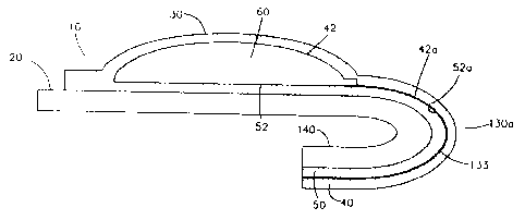
[00261 Fig. la is a plan view of a first embodiment of a unitized package.
10027] Fig. lb is a cross-sectional view of the unitized package of Fig. la
along A-A.
CA 02865059 2014-08-19
WO 2013/126621 PCT/US2013/027210
6
100281 Fig. 2 is a plan view of a second embodiment of a unitized package
with a reelosable
fluid vessel.
[00291 Fig. 3a is a plan view of a lower platen for fabricating the first
laminate barrier layer
of the unitized package.
[00301 Fig. 3b is a cross-sectional view of the lower platen of Fig. 3a
along B-B.
[00311 Fig. 4a is a side view of a lower platen and an upper platen for
fabricating the first
laminate barrier layer of the unitized package, before pressurized gas is
applied.
[00321 Fig. 4b is a side view of the lower and upper platens of Fig. 4a,
when the pressurized
gas is initially applied.
100331 Fig. 4c is a side view of the lower and upper platens of Fig. 4a,
when the pressurized
gas is fully applied.
[00341 Fig. 5a is a plan view of an embodiment of a unitized package.
[00351 Fig. 5b shows the unitized package of Fig. 5a with the opening strip
removed.
[00361 Fig. Sc shows the folding flap of the unitized package of Figs. 5a
and 5b in a folded
position.
[00371 Fig. 5d shows the folding flap of the unitized package of Figs. 5a
to 5c inserted into
locking tabs.
[00381 Fig. 6a is a cross-sectional view of an embodiment of a unitized
package with
opening strip removed.
[00391 Fig. 6b shows the folding flap of the unitized package of Figs. 6a
in a folded
position.
[00401 Fig. 6c is an enlarged view of the folding flap in a folded position
that is shown in
Fig. 6b.
DETAILED DESCRIPTION OF THE INVENTION
I. Unitized Packages
[00411 The present unitized package generally comprises a printed base card
and a fluid
vessel permanently bonded to a portion of the base card. The fluid vessel
comprises a first
laminate barrier layer and a second laminate barrier layer enclosing a product
material. The first
laminate barrier layer comprises at least one layer of a biaxiall.y oriented
thermoplastic polymer,
CA 02865059 2014-08-19
WO 2013/126621 PCT/US2013/027210
7
and a portion of the first laminate barrier layer is formed into a modified
monolithic dome shape.
The second laminate barrier layer is planar.
[00421 Fig. 1 a shows a first embodiment of the present unitized package.
The unitized
package 10 includes a printed base card 20 and a fluid vessel 30. Fig. lb
shows a cross-sectional
view of the unitized package 10 in Fig. la along A-A. As shown in Fig. lb, the
fluid vessel 30
comprises a first laminate barrier layer 40 and a second laminate barrier
layer 50. The first
laminate barrier layer 40 has an inner surface 42 and an outer surface 44. The
second laminate
barrier layer 50 has an inner surface 52 and an outer surface 54. The inner
surface 42 of the first
laminate barrier layer 40 and the inner surface 52 of the second laminate
barrier layer 50 are
sealed together at their perimeters, forming a fluid-tight enclosure 60. A
product material 70
substantially fills the volume of the fluid-tight enclosure 60.
[00431 The first and second laminate barrier layers are barrier layers,
i.e., they are
substantially inert and preferably impermeable to the product material
contained in the fluid
vessel in order to substantially prevent migration of components of the
product material through
the layers. Various types of plastic film with barrier property, e.g.,
polyethylene terephtalate
("PET"), cellul.oses or acetates, may be used to fabricate the laminate
barrier layers. The
laminate barrier layers may also incorporate specialty vapor barrier coatings
to impart or enhance
their barrier characteristics. In addition, a material that does not possess
barrier properties may
be coated or treated in order to give it barrier properties so that the
material may be used to form
the laminate barrier layers. Depending on the components of the product
material, a barrier
material may be chosen which is a barrier to, for example, oil, gas, water
vapor, aroma, or
oxygen.
[00441 The first laminate barrier layer and the second laminate barrier
layer of the unitized
package are preferably constructed with thin flexible thermoplastic barrier
laminations. The first
laminate barrier layer comprises at least one layer of a biaxially oriented
thermoplastic polymer.
A biaxially oriented thermoplastic polymer is a polymer that has been
stretched in two directions
(i.e., the machine direction and cross-machine direction) under conditions
that result in the
reorientation of the polymer. As a result of such polymer orientation, the
barrier characteristics
and the physical strength of the polymer are improved. A biaxially oriented
thermoplastic
polymer has a substantially high tensile strength in either machine or cross
machine direction,
and is generally resistant to further elongation.
CA 02865059 2014-08-19
WO 2013/126621 PCT/US2013/027210
8
100451 Suitable biaxially oriented thermoplastic polymers include, but are
not limited to,
polyesters, polyamides which includes nylons and amorphous polyamides,
polyarylates,
polypropylenes, polyethylenes, or mixtures thereof.
[00461 A preferred biaxially oriented thermoplastic polymer is a polyester
such as
polyethylene terephthalate (PET), sold under the trade name MYLAR
manufactured by DuPont
Tejlin Films, due to the comparable strength and elongation characteristics of
the polyester film
along both machine and cross machine directions. Other preferred biaxially
oriented
thermoplastic polymers include, but are not limited to, polyamides such as
nylon film, sold under
the trade name Capran Emblem.* manufactured by Honeywell, and biaxially
oriented
polypropylene films (BOPP) such as those manufactured by Exxon-Mobil.
[00471 In addition, the first and second laminate barrier layers may each
comprise more than
one layer of composite materials.
[00481 The first and second laminate barrier layers may also each
incorporate metallic, semi
metallic, metal oxide or ceramic materials to improve the moisture--vapor
characteristics of these
layers. Examples of such lamination construction may include those
manufactured in
accordance with U.S. Military specification Mil-B-131 Class I , as well as
many commercial
laminations such as those used for medical diagnostic testing or distribution
of food service
condiments.
100491 In one embodiment, the first and the second laminate barrier layers
may each
comprise a layer of thin gage metal. The metal layer, such as an aluminum foil
layer, provides
for low moisture vapor transmission rates that are desired in squeezable
containers. Any
aluminum grades may be used, though those that are more malleable are
preferred. A
particularly preferred aluminum, is a thin gage aluminum layer which does not
cause loss of the
desirable resilient characteristics of the sealed fluid vessel, is not easily
dented or otherwise
dam.aged in transportation, and yet provides the desired reduction in moisture
vapor or oxygen
transmission rate.
[00501 In one embodiment, the first laminate barrier layer may comprise an
inner
thermoplastic heat seal layer with thickness in the range of about 0.0005
inches to about 0.0040
inches and an outer layer of a biaxially oriented thermoplastic polymer film
with thickness in the
range of about 0.0004 inches to about 0.002 inches. A supplemental barrier
layer, preferably an
aluminum foil layer, with thickness in the range of about 0.00027 inches to
about 0.001 inches
CA 02865059 2014-08-19
WO 2013/126621 PCT/US2013/027210
9
may also be included between the heat seal layer and biaxially oriented
thermoplastic film.
Preferably, the outer layer is constructed with a biaxially oriented polyester
polymer film with
thickness in the range of about 0.00048 inches to about 0.00092 inches.
[00511 The second laminate barrier layer may have the same or different
compositions as the
first laminate barrier layer. Because the second laminate barrier layer is not
formed, use of a
biaxially oriented thermoplastic film in the structure is not required.
[00521 As shown in Fig. lb, the first laminate barrier layer 40 has a
modified monolithic
dome shape formed therein. The terms "modified monolithic dome shape" or
"modified dome
shape", as used in this application, refer to any suitable three-dimensional
protrusion with a
smooth surface from a planar base, and include, but are not limited to, a
hemisphere shape, a low
profile sphere shape (e.g., the height of the profile is less than the radius
of the base in the case of
a circular base), or a torus shape. Preferably, the modified dome shape is a
low profile sphere
shape, such as that shown in Fig. lb.
[00531 The planar base of the modified dome shape may have any desired
shape, preferably
a rounded shape, and any desired dimensions. The modified dome shape in Fig.
la has a circular
base. Other suitable bases of the modified dome shape include, but are not
limited to, ovals,
ellipses or simple squares or rectangles with soft radius corners (as shown in
Fig. 2).
[00541 Any portions of the first laminate barrier layer that do not have
the formed modified
dome shape (i.e., the portions surrounding the planar base of the formed
shape) are preferably
planar. Preferably, the second laminate barrier layer is also planar.
[00551 The product material may be any material that is suitable to be
packaged and
distributed in a unitized package. Preferably, the product material is a
substantially
unadulterated cosmetic, personal care product, medical product, or household
product.
Examples include face cream, shampoo, toothpaste, liquid medicine, and
detergent.
Substantially unadulterated products include any product materials presented
in their original or
natural form, without being altered in any significant way. The product
material may be
presented in any suitable form, such as in a gel form, in a powder form, in
microcapsules,
contained in a matrix material, or, preferably, in a liquid form. In addition,
the product material
may comprise volatile and/or non-volatile components. The quantity or volume
of the product
material may be suitable as a sample, or for single or multiple uses.
CA 02865059 2014-08-19
WO 2013/126621 PCT/US2013/027210
[0056] Preferably, the product material substantially fills the volume
defined by the modified
dome shape of the first laminate barrier layer.
[00571 The first and second laminate barrier layers 40 and 50 are sealed
together at their
perimeters. As shown in Fig. lb, the inner surface 42 of the first laminate
barrier layer 40 and
the inner surface 52 of the second laminate barrier layer 50 are sealed
together at their
perimeters, forming a fluid-tight enclosure 60 for containing the product
material 70. The seal
may be formed using any suitable method, such as by heat sealing, by radio
frequency or sonic
energy, or by adhesives. Preferably, the seal is a hermetic permanent seal.
Permanent seals, also
referred to as destruct or tear bonds, may be formed by the methods described
above.
10058) Adhesives must be compatible with the product material, i.e., they
should not react or
become plasticized when they come into contact with the product material or
components of the
product material. Such reaction may cause undesirable deterioration of the
product material or
the seal.
[0059i in one embodiment, at least one of the inner surfaces 42 and 52
comprises a pressure
sensitive adhesive, such as a low odor pressure sensitive adhesive that has
been applied from a
water borne emulsion. The pressure sensitive adhesive may cover the entire
contact area
between the first laminate barrier layer and the second laminate barrier
layer. Alternatively, the
adhesive may be applied in a specific pattern of lines or dots. Another
example is specialty
grades of hot melt adhesive, especially those that can provide a cross link
functionality. Also,
adhesives may be formulated to provide additional barrier properties. Such
adhesives may
contain agents such as oxygen scavengers or consist of film-forming precursors
of high-barrier
materials, such as latex-grade polyvinylidene chloride (PVdC).
100601 if a permanent seal is used, the unitized package 10 also must be
provided with a
means for opening the fluid vessel 20, such as by tearing one of the first
laminate barrier layer or
the second laminate barrier layer, or both. The opening means may include a
dispensing tip 100
as shown in Fig. la, a notch or a string to originate or facilitate the tear.
The opening means
may also be reclosable or resealable.
1(1061) When the first and second laminate barrier layers 40 and 50 are
sealed together at
their perimeters to form a fluid-tight enclosure 60, the product material 70
substantially fills the
volume of the enclosure (i.e., the volume defined by the modified dom.e shape
of the first
laminate barrier layer), and leaves minimal head space (i.e., the space that
is occupied by
CA 02865059 2014-08-19
WO 2013/126621 PCT/US2013/027210
11
ambient air) in the enclosure. By utilizing the defined volume of the
enclosure to the fullest
extent, maxi.m.um. stability of the contained product material may be
achieved. Also, the product
material, especially when in fluid form, and other fluids (i.e., liquid or
gas) in the enclosure if
any, provide internal pressure and force to sustain the formed shape of the
first laminate barrier
layer. Thus, when the fluid vessel is sealed, the formed modified dome shape
of the first
laminate barrier layer is resiliently sustainable, i.e., the layer will show
minor pressure
deformation when force is applied to its outer surface, but will substantially
self restore to its
original shape on release of the force. Also once formed and sealed, the fluid
vessel is resistant
to flexing and may contribute to the rigidity of the base card.
10062] In a preferred embodiment, the inner surface 42 of the first
laminate barrier layer 40
is heat sealed to the inner surface 52 of the second laminate barrier layer 50
prior to bonding the
fluid vessel 30 to the base card 20.
[0063] The outer surface 54 of the second laminate barrier layer 50 is
permanently bonded to
a portion of the base card 20. The second laminate barrier layer may be bonded
with a
laminating adhesive, or by any other suitable attachment means, such as by
adhesives activated
by heat, moisture, pressure, drying or radiation curing. In one embodiment, a
full bleed adhesive
system is incorporated into the outer surface 54 of the second laminate
barrier layer 50.
Preferably, the full bleed adhesive system comprises a permanent pressure
sensitive adhesive
such as a permanent pressure sensitive acrylic adhesive. The permanent
pressure sensitive
adhesive may be covered and protected by a release liner such as a disposable
silicone coated
release liner.
[0064] Any desired material may be used for fabricating the base card.
Since the enclosure
formed by the first and second laminate barrier layers is fluid tight and also
is preferably formed
prior to bonding to the base card, the base card material will not be exposed
to the product
material contained in the enclosure; nor will it be exposed to the heat or
other energies used for
sealing the first and second laminate barrier layers. Suitable materials for
the base card include
but are not limited to paper such as cover grade or light gage tag stock.
Synthetic paper or other
plastic materials may also be used. Preferably, the base card comprises a
paper stock for
environmental reasons and overall cost efficiency. Paper of varying grades and
compositions,
including recycled, colored, textured, coated, or uncoated, may be used. In
one embodiment, the
base card is fabricated from grades of solid bleached sulfite paperboard or
coverstocks, and has a
CA 02865059 2014-08-19
WO 2013/126621 PCT/US2013/027210
12
thickness in the range of about 0.006 inches to about 0.024 inches. The base
card may also be
coated with various water based or energy cured polymer coatings, or
overlaminated with
thermoplastic films to protect the paper and any printed graphics from
humidity damage.
[00651 Preferably, the base card has a sufficiently large surface area
extending beyond the
fluid vessel so that any desired advertising artworks, texts, graphics,
product information or
instructions, or drug ingredient information may be printed on any surface of
the base card.
Also, the fluid vessel may be positioned or sized such that sufficient surface
area on the base
card is available to achieve brand promotion, consumer education, or
compliance with any
applicable regulatory requirements such as those imposed by the U.S. Food and
Drug
Administration. Since the fluid vessel is permanently bonded to the printed
base card, the
presence of any product marketing or instructional information printed on the
base card is
ensured at the time of use.
[00661 The printed base card may be of any suitable dimension or
configuration as long as
there is a planar surface to which the fluid vessel may be permanently bonded.
As shown in Fig.
la, the printed base card may be planar. The printed base card may also be
scored or otherwise
folded to form a common 4 or 6 page format. Such configuration functions to
substantially
increase the usable surface of the base card, while limiting the finished
dimensions. The printed
base card may also be folded such that it can stand up vertically. The base
card may also
comprise a portion of a panel incorporated as a portion of a die cut box or a
greeting card. As a
further example, the folded base card may provide reduced finished dimensions
to facilitate
placement of the unitized package into an existing host container or to fall
within the scope of
desired U.S. Postal mailing dimensions. The base cards may also contain a hang
hole for retail
peg display purposes.
[00671 As shown in Fig. la, the printed base card 20 may have an opening
strip 80 defined
by a line of perforation 90 intersecting the dispensing tip 100. When the
opening strip 80 is
removed by tearing or cutting along the line of perforation 90, the fluid
vessel 30 will be opened,
thus allowing access to the product material 70.
190681 The fluid vessel 30 may also comprise a planar extension tab 110
which is
permanently bonded to the printed base card 20. As shown in Fig. la, the
extension tab 110 is
formed from. the first laminate barrier layer 40 and the second laminate
barrier layer 50. The
dispensing tip 100 is enclosed between the lower edge 112 and the upper edge
114 of the
CA 02865059 2014-08-19
WO 2013/126621 PCT/US2013/027210
13
extension tab 110. The extension tab 110 overlays the opening strip 80, with
its lower edge 112
and the line of perforation 90 on the printed base card 20 being superimposed.
Thus, when the
base card is torn. or cut along the line of perforation 90, the extension tab
110 and the opening
strip 80 will both be removed, and the product material 70 may be accessed.
[00691 The printed base card may also incorporate a recl.osable or
resealable feature for the
fluid vessel. The manufacturing method and unitized design of the current
invention is highly
advantageous in achieving this desirable function. The manufacturing cost and
reliability of the
closure provided by this embodiment is highly effective as compared to that of
prior devices.
For example, as shown in Fig. 2, the printed base card may incorporate two
lines intersecting the
dispensing tip 100. The first line 120, is a perforation and defines an
opening strip 80. The
second line 130, is a score line and defines a folding flap 140. The distance
between the two
lines may be any desired distance. In certain embodiments, the distance is
preferably about 0.25
inches or greater, or about 0.5 inches or greater.
[00701 The printed base card of the product embodiment shown in Fig. 2 may
be of any
thickness determined to adequately provide the required rigidity and thickness
to insure function.
In certain embodiments, the thickness of the printed base card is about 0.005
inches or greater;
about 0.008 inches or greater; or about 0.010 inches or greater. Re-closing of
the fluid vessel is
accomplished by folding the printed carrier card and corresponding dispensing
tip along the
score line 130. In a preferred embodiment the folding flap 140 is folded or
bent so that the
printed carrier card completely folds back on itself. Alternative designs also
include folding or
'bending of the carrier card to form a right angle. The printed carrier is
designed in such a way to
insure that after bending, the dispensing tip of the fluid vessel is on the
outside corner of the fold.
[00711 The base card further contains design means of retaining the printed
carrier in a bent
state in order to insure sustained tension of the flexible barrier layers and
proper sealing. In
accordance with the embodiment illustrated by Fig. 2, the base card further
contains at least one
locking tab 145. When the opened unitized package of Fig 2 is not in use, the
folding flap 140
may be folded along the score line 1.30 and inserted under the locking tabs
145, thus preventing
the product 70 from being released from the enclosure 60.
[00721 Various alternative means for retaining the printed carrier in a
folded state may be
used in addition to the embodiment illustrated in Fig. 2 without departing
from the spirit of the
invention. For example, pressure sensitive tape tabs, dead fold wire closures,
strings and
CA 02865059 2014-08-19
WO 2013/126621 PCT/US2013/027210
14
buttons, loops and hooks can be used. The score fold line 130 can also be
retained by
incorporation of printed carrier designs that include compound folds, or slide
and sleeve designs.
[00731 Figs. 5a to 5d illustrate how a folding flap of a unitized package
is folded or bent and
inserted into one or more locking tabs. Fig. 5a shows a unitized package 10
having two lines
that intersect the dispensing tip 100. The line of perforation 120 defines an
opening strip 80.
The score line 130 defines a folding flap 140. In Fig. 5b, the opening strip
80 has been removed
along the line of perforation 120. In Fig. Sc, the folding flap 140 is folded
along the score line
130 to reclosably seal the dispensing tip 100, which prevent the product
contained in the fluid-
tight enclosure 60 from being released from the enclosure. The dispensing tip
can be unsealed
by unfolding the fold. The dispensing tip can be sealed and unsealed
repeatedly. In Fig. 5d, the
folding flap 140 is inserted into one or more locking tabs 145. In other
embodiments, the folding
flap does not have to be inserted into any locking tabs.
[00741 Folding of the printed carrier and mounted dispensing tip places the
first and second
laminate barrier layers of the vessel in a state of static tension around the
radius of the bend. The
thickness of the printed carrier is most desirably selected with the intent of
placing the portions
of the inner surfaces of the flexible barrier layers that define the
dispensing tip or nozzle to fall
substantially outside the neutral point of the fold and in the tension zone of
the unitized package
at score line 130. Although the primary tension applied to the laminate
barrier layer is in a
direction perpendicular to the score line 130, there is also a tendency for a
secondary physical
response resulting in the laminate barrier layer(s) to also come under tension
in the direction
parallel to the score line 130. This secondary tension advantageously serves
to further smooth
and tighten the portions of the inner surfaces of the first and second
laminate barrier layers that
define the dispensing tip or nozzle. The result is a fluid tight mechanical
closure able to resist
penetration or migration by even low viscosity fluid materials.
[00751 Fig. 6a shows an embodiment of a unitized package 1.0, which
comprises a
dispensing tip 100. A portion of the inner surface of the first laminate
barrier layer 42a and a
portion of the inner surface of the second laminate barrier layer 52a define
the dispensing tip
100. The printed carrier or base card 20 has a score line 130. In Fig. 6b, the
folding flap 140 is
folded along the score line 130 to form a fold or bend 130a. When the folding
flap 140 is folded,
the portions of the inner surfaces of the first and second laminate barrier
layers that define the
dispensing tip 42a, 52a come into contact with each other along an interface
133. Fig. 6C is an
CA 02865059 2014-08-19
WO 2013/126621 PCT/US2013/027210
enlarged view of the fold 130a of Fig. 6b. At the fold 130a, the first and
second laminate barrier
layers 40, 50 are in tension and the printed carrier 20 is under compression.
The thickness of the
printed carrier 20 is selected such that portions of the inner surfaces of the
first and second
laminate barrier layers that define the dispensing tip 42a, 52a fall
substantially outside the
neutral point of the fold 130a, (which is not under tension or compression),
and in the tension
zone of the unitized package at score line 130.
[00761 The practical application of a reclosable feature in an embodiment
of the current
unitized package is commercially viable due to the construction and
manufacturing method of
the unitized package. Most significantly the fluid vessel is formed, filled,
sealed and thereafter
bonded to a flat carrier substrate. The thickness, rigidity and physical
nature of the carrier do not
influence the sealing process. As well, the bonded process advantageously does
not require the
use of heat. Further still, the bonding method allows for full, smooth and
uniform contact
between the flat surface of the printed carrier and the laminate barrier
material. The strength,
smoothness and continuity of this bond being significant to the ability of the
dispensing tip to
achieve a fluid tight seal on bending.
IL Method of Manufacturing the Unitized Packages
[00771 The present unitized packages may be manufactured using various
methods. The
methods generally include the following manufacturing steps: providing a
printed base card;
forming a fluid vessel; and permanently bonding the fluid vessel to a portion
of the printed base
card. Generally, the fluid vessel is fabricated by forming a portion of the
first laminate barrier
layer into a modified dome shape; depositing the material into the volume
defined by the
modified dom.e shape; disposing the second laminate barrier layer on the
formed first laminate
barrier layer; and sealing the first laminate barrier layer and the second
laminate barrier layer
together at their perimeters to form a fluid-tight enclosure for containing
the product material.
The materials described above in Section 1 for the unitized package may also
be used in the
method.
[00781 The printed base card may be made before or after the fluid vessel
is made.
Preferably, the printed base card is made prior to the manufacture of the
fluid vessel.
[00791 As described above, the base card may be fabricated from a variety
of substrates,
preferably from grades of solid bleached sulfite paperboard or cover stocks.
Texts or graphics
CA 02865059 2014-08-19
WO 2013/126621 PCT/US2013/027210
16
regarding product information may be printed or otherwise decorated on any
surface of the base
card using any suitable method. Preferred print methods include, but are not
limited to, sheet fed
offset, web offset, flexographic and digital imaging. The surface of the
printed base card may
further be coated with a UV cured polymerization coating, film lamination, or
alternate coatings
to impart water resistant and improved lay flat character to the base card
material.
[00801 In one embodiment, the base card is further precision die cut to
form a line of
perforation or other cut line defining an opening strip that facilitates clean
opening of the fluid
vessel.
[00811 Any suitable method may be used for fabricating the fluid vessel of
the present
unitized package. The various steps for making the fluid vessel may be
performed continuously
on different stations of a manufacturing sequence. The fluid vessel may be
fabricated
individually or, more preferably, in multiple quantities. An example of a
method for making
multiple fluid vessels is described below.
[00821 The first laminate barrier layer 40 of the fluid vessel may be cold
formed at the first
station of the manufacturing sequence. Any suitable stress force may be used
in the cold
forming process, e.g., fluid pressure or vacuum. Preferably, the stress force
is pressurized gas.
[00831 Figs. 3a to 4c show an example of an assembly at a first
manufacturing station that
may be used to form. the modified dome shape in the first laminate barrier
layer. As shown in
Fig. 4a, the first manufacturing station is comprised of a high pressure
platen assembly with two
opposing surfaces, i.e., an upper platen 150 and a lower platen 160.
Preferably vertical motion
of at least one of the upper or lower platens is provided.
[00841 The upper surface of the lower platen 160 comprises a plurality of
facings 170 with a
uniform profile. Each of the facings contains a cavity 180. Figs. 3a-4c show
one such facing
170. The facing may be fabricated with any suitable resilient material using
any suitable
method.. Preferably, the facing is fabricated with silicone rubber with a
durometer value in the
range of about 40 to about 80 and with a thickness in the range of about 0.125
inches to about
0.250 inches. The silicone rubber facing may be used as the lower platen
facing or further
laminated or otherwise bonded to a pressure resistant and machinable material,
e.g., medium
density fiberboard (MDF), to form the lower platen facing 170. The thickness
of the lower
platen facing 170 may be adjusted in accordance with the specific design of
the fluid vessel. For
example, it is in the range of about 0.125 inches to about 1.0 inches.
CA 02865059 2014-08-19
WO 2013/126621 PCT/US2013/027210
17
100851 The lower platen facing 170 may be cut or otherwise machined to form
a plurality of
cavities therein. Figs. 3a-4c shows one such cavity 180. The planar shape of
the cavity 180
determines the shape of the base of the formed modified dome shape of the
first laminate barrier
layer, which includes, but is not limited to, circles, ovals, ellipses or
squares or rectangles with
soft radius corners. The side wall 182 of the cavity 180, generally a simply
cut perpendicular to
the planar surface of the lower platen 160, does not contact the formed shape
of the first laminate
barrier layer and therefore need not be polished. The cavity in the lower
platen facing functions
in lieu of a forming die otherwise utilized in conventional thermoforming
processes.
[00861 The lower surface of the lower platen facing 1.70 is constructed to
facilitate limited
flow of air between the lower platen facing 170 and the lower surface of the
lower platen 160.
As shown in Figs. 3a and 3b, each lower platen facing 170 may comprise one or
more vent
holes 190.
[00871 As shown in Fig. 4a, the upper platen 150 is fitted with air supply
channels 200 that
correspond with each cavity 180 in the lower platen facings 1.70.
100881 The preferred manufacturing process uses an intermittent web motion.
The first
laminate barrier layer 40 is drawn forward into the first station as a planar
web in a horizontal
orientation. The outer surface 44 of the first laminate barrier layer 40 faces
downward and is
engaged by the lower platen 160 and the inner surface 42 is engaged by the
upper platen 150.
The upper platen 150 and lower platen 160 are then engaged by clamping force
and the first
laminate barrier layer 40 is secured at the perimeters of the cavity 180 of
the lower platen facing
170.
[00891 Pressurized gas 210 is introduced into the upper platen 150 through
the air supply
channels 200. As shown in Fig. 4b, as the fluid gas pressure imposed on the
inner surface 42 of
the first laminate barrier layer 40 builds up (the presence of the vent holes
190 on the lower
platen facing 170 relieves or reduces any opposing pressure), the portion of
the first laminate
barrier layer 40 within the side wall 182 of the cavity 180 starts to deform
under stress and
bulges into the cavity 180 to form a modified dome shape. The gas pressure is
controlled such
that the corresponding stress force does not exceed the ultimate tensile
strength of the biaxiall.y
oriented thermoplastic polymer. As such, the deformation does not
significantly alter the
desirable physical properties of the original biaxiall.y oriented
thermoplastic polymer; instead, it
increases the degree of polymer orientation.
CA 02865059 2014-08-19
WO 2013/126621 PCT/US2013/027210
18
10090] A suitable gas pressure is in the range of about 10 psi to about 140
psi, preferably in
the range of about 40 psi to about 100 psi. Under such pressure, the first
laminate barrier layer
comprising a biaxially oriented thermoplastic polymer layer can undergo
further biaxial
elongation typically in the range of about 10 to about 25% before reaching its
breaking point.
[0091i In Fig. 4c, the gas pressure is fully applied. After the pressure
reaches its desired
level, the pressurized gas 210 is switched off and the pressure is removed.
Minor shrinkage of
the formed fluid vessel profile may subsequently occur due to partial elastic
recovery of the
biaxially oriented thermoplastic polymer. This partial recovery is not
detrimental to the resulting
profile.
(00921 The modified dome shape formed under the present process has a large
radius
curvature extending from the planar base where the first laminate barrier
layer is located prior to
the forming process. The maximum depth of draw is highly influenced by the
geometric shape
of the original plane area subject to the forming process (i.e., the planar
shape of the cavity 180).
Therefore, the formed shape of the first laminate barrier layer is a result of
the response of the
planar laminate film to the internal pressure. Moreover, this formed shape is
resiliently sustained
until time of use by the internal gas or fluid inflation provided by the
product materials and.
ambient air enclosed in the fluid vessel, without the need for any rigid
vertical oriented sidewalls
to impart structural strength. Other portions of the first laminate barrier
layer that have not been
subject to the forming process remain planar.
[0093] The use of a biaxially oriented thermoplastic polymer and
pressurized gas allows for
controlled redistribution of the stress force with progressive polymer chain
slip and prohibits
mechanical "hot spots" that would otherwise weaken the film or cause ultimate
failure.
Additionally, as the biaxially oriented thermoplastic polymer is elongated
under tensile stress,
resistance to further elongation is increased. The increased degree of
orientation and resistance
to further elongation is also biaxial in nature. As a result, the stressed
polymer uniformly
redistributes the tensile strain and prevents thinning of the polymer that
would otherwise occur.
Biaxially oriented PET, with its closely comparable mechanical values in the
machine and cross
machine directions, is a preferred biaxially oriented polymer. The use of
resilient rubber on the
lower platen facing also prevents mechanical hot spots or stress points at the
perimeter of the
cavity 180 that may otherwise lead to stress failure. The present process
eliminates
CA 02865059 2014-08-19
WO 2013/126621 PCT/US2013/027210
19
complications and quality issues such as buckling, wrinkling or tearing
commonly associated
with the stretch methods commonly used in forming processes.
[00941 As described above, a thin gage metal layer, such as an aluminum
layer, may also be
incorporated in the first laminated barrier layer. The presence of a biaxially
oriented
thermoplastic polymer in the same laminate barrier layer as the aluminum layer
also prevents
cracking or tensile failure of the gage metal during the forming process as it
distributes the stress
force during the forming process and prevents localized metal elongation to
the point of failure.
100951 Other suitable methods may be used to apply pressure to the first
laminate barrier
layer to form the modified dome shape therein.
[00961 Subsequent to forming, the upper platen 150 is lifted and the formed
first laminate
barrier layer 40 is advanced to the second station of the manufacturing
sequence where the
product material 70 is filled. For example, the product material 70 may be
metered and
discharged from fluid nozzles mounted directly over the volume defined by each
of the modified
dome shapes. Metering and pumping may take place while the intermittent web
motion is
stopped and may be accomplished through the use of a variety of suitable
pumping and metering
systems. The product material dispensed preferably substantially fills the
volume of the formed
modified dome shape. Leveling of the product material is not required and
higher viscosity
product material may temporarily stand above the plane of the inner surface 42
of the first
laminate barrier layer 40. Also, disposing the product material in the formed
modified dome
shape may prevent unwanted outward spread of the product material otherwise
occurring due to
momentum associated with the preferred intermittent web motion process.
[00971 At the next manufacturing station, a planar second laminate barrier
layer 50 is then
disposed on the inner surface 42 of the first laminate barrier layer 40.
Preferably, the second
laminate barrier layer 50 comprises a pressure sensitive adhesive on its inner
surface 52, which is
covered and protected by a silicone coated disposable release liner (not
shown). The first and
second laminate barrier layers 40 and 50 are then indexed and moved forward to
a heated platen
where these two layers are sealed together at their perimeters to form a fluid-
tight enclosure 60.
The product material 70 is automatically smoothed and redistributed in the
enclosure 60 by the
planar inner surface 52 of the second laminate barrier layer 50 just prior to
or during the heat seal
process. In a preferred embodiment, a dispensing tip 1.00 is formed through
the use of a simple
machined relief in the lower surface of the heated upper platen. The remaining
sealing takes
CA 02865059 2017-02-17
place in such a manner that only the planar portion of the first laminate
barrier layer is sealed and
the modified dome shape is not disturbed.
100981 The sealed first and second laminate barrier layers are then
precision die cut to form
individual fluid vessels. In a preferred method, the first and second laminate
barrier layers are
kiss cut together with a full bleed permanent pressure sensitive adhesive such
as a permanent
pressure sensitive acrylic adhesive against a release liner such as a
disposable silicone coated
release liner. The individual fluid vessels are mounted in a predetermined
pattern on the
disposable silicone coated release liner. The fluid vessels are generally not
flexible when sealed.
100991 The fluid vessel is then permanently bonded to the printed base
card. This step may
be accomplished by any suitable method. In a preferred embodiment, the
disposable silicone
coated release liner is removed and the second laminate barrier layer is
bonded to the base card
by the full bleed permanent pressure sensitive acrylic adhesive.
[001001 The present unitized package may be used as a product for single use
or multiple
uses. It may also be used as a sampling package. A consumer may open the fluid
vessel, for
example, by tearing off the opening strip along the line of perforation on the
base card. The
product material may then be dispensed by gently applying pressure on the
outer surface of the
first laminate barrier layer. Because the line of perforation provides a clean
opening point of the
fluid vessel, the product material may be dispensed in a controlled manner.
Alternate methods of
opening the fluid vessel include, but are not limited to; tear strings, peel
off tabs, scoring of one
or both of the laminate barrier layers such as with lasers, peel off header
strips or frangible or
peelable perimeter seals. Additionally, since the fluid vessel is permanently
bonded to the
printed base card, any marketing or product information printed on the base
card is readily
available at the time of use.
100101] The description contained herein is for purposes of illustration and
not for purposes of
limitation. Changes and modifications may be made to the embodiments of the
description and
still be within the scope of the invention.