Note: Descriptions are shown in the official language in which they were submitted.
CA 2,865,081
CPST Ref: 11508/00001
SYSTEM AND METHOD FOR TREATING PRODUCED, DESALTED AND FLOW BACK
WATER
TECHNICAL FIELD OF INVENTION
[0001] The presently disclosed embodiments are directed to a system and
method for treating
produced and flow back water and wastewater from processes such as desalting
associated with recovery
of crude oil and natural gas from reservoirs and the preparation of water to
be used for enhanced oil recovery
(EOR) and other requirements such as desalting and hydrofracturing.
BACKGROUND OF INVENTION
[0002] Petroleum, also commonly referred to as oil, consists of a complex
mixture of
hydrocarbons of various molecular weights, plus other organic compounds.
Petroleum is a naturally
occurring liquid found in rock formations. It is generally accepted that oil
is formed mostly from the carbon
rich remains of ancient plankton after exposure to heat and pressure in the
Earth's crust over hundreds of
millions of years gradually transforming into oil and natural gas reservoirs.
Petroleum is a vital component
of the world's supply of energy as a source of providing heating and
electricity. It is also used as fuel for
vehicles when refined, and as a chemical feedstock in the manufacture of
plastics and other commercially
important organic chemicals. Worldwide consumption of oil is approximately
thirty billion barrels (4.8
km') per year, with developed nations being the largest consumers. For
example, the United States
consumed about 25% of the oil produced in 2007. Petroleum is found in deep
underground natural rock
formations and may be associated with other hydrocarbons such as natural gas.
[0003] Oil reservoirs may be located deep within the Earth's crust. As
recovery technology
advances, oil recovery methods are being performed in deeper locations within
the Earth, most notably in
offshore and deep ocean locations. For example, deep ocean drilling rigs are
now drilling in water depths
at or in excess of 2,000 meters. Similarly, there is much activity at land
based locations.
[0004] Oil recovery may take a variety of forms and methods. For example,
once a reservoir is
identified, an oil well is created by drilling a long hole into the Earth. A
steel pipe, known as a casing, is
placed in the hole to provide structural integrity to the newly drilled well
bore. Holes are then made in the
base of the well to enable oil to pass into the
CPST Doc: 303413.1 1
Date Recue/Date Received 2020-11-02
CA 02865081 2014-08-20
WO 2013/126625
PCT/US2013/027215
bore, which oil is then removed by various methods. Typically, recovered oil
includes
various other secondary byproducts such as natural gas, inorganic compounds
and water
associated with it. As wells mature, various techniques are employed to
extract as much oil
as possible. These techniques are commonly referred to as enhanced oil
recovery (FOR.).
One of these techniques injects treated water into a reservoir to displace the
oil. This
technique requires that the water is of specific quality which necessitates
treatment prior to
injection. Another technology being used to recover previously unrecovered oil
is hydraulic
fracturing. This is a technique used to create fractures in rock with a
hydraulic fluid,
typically water with additives, under high pressure to release trapped
hydrocarbons.
o [0005] Crude
primary treatment techniques may comprise multistep processes. For
example, a technique may include first separating byproducts from raw crude
oil, followed by
desalting the crude oil. The byproducts and the raw crude are separated in a
device called a
separator or dehydrator which removes water. There are several types of
separators
depending on the feed stream and the separation objectives. Crude oil, natural
gas, produced
water, bottom sludge which is typically sand, and other inert compounds are
separated. The
oil is then washed with water to remove the salts that are trapped within the
crude oil, i.e.,
desalting. The washing removes salts and generates a wastewater stream that
contains
dissolved salts, suspended material, oil, benzene, ethylbenzene, toluene and
xylenes (BETX),
and in some cases heavy metals.
[0006] Typical crude oil separation methods generate substantial quantities
of waste.
Such systems can generate from as little as 5,0(X) barrels per day (BPD) to
upwards of
300,000 BPD. Waste water is generated from the water associated with the
recovered
hydrocarbons as well as water used to desalt the crude oil. The
characterization of the water
will vary according to its content As oil and gas production wells mature,
there is an
as increased percentage of produced water being generated. Produced water
lirnits the capacity
of crude oil transportation by corroding conveyance systems.
[0007] Regulations
related to discharge of produced water vary by the authorities
involved and the location receiving the waste stream_ Table 1 represents
typical waste water
stream and associated regulatory discharge levels.
Constituent PPM Range (unless I Typical Discharge limits --- PPM
otherwise noted) (unless otherwise noted)
Free Oil & grease 100 ¨ 1000 <15
2
CA 02865081 2014-08-20
WO 2013/126625
PCT/US2013/027215
BUD 100 - 2000 150
COD 1000 - 5000 Varies
Temperature 25 200 deg. C 40 deg. C
_Hydrogen Sulfide 0 - 100
Ph 6 - 8 I Varies
-1-DS 50,000- 300,000 'Varies -platform deep ocean
dilution
TSS 100-- 1000 150
Ammonia 0 - 100
Sulfates 500 - 5000
Heavy Metals 10- 200 Varies by metal < 1.5
Silica 100 - 2000
Sodium 30,000+
Chloride 30,000+
Hardness 1000+
iron 10 100
Morena_ _____________ 1 - 10 , 0.01
Oxygen 5-10
Table I
NOM As the
amount of crude oil recovered increases and additional water based
enhanced techniques are used, the amount of produced water generated also
increases,
thereby creating serious environmental challenges to be addressed. Issues such
as the
contamination of water ways such as stream, lakes, groundwater with water
containing, oil,
grease, hydrocarbons, metals, etc., must be prevented, some of which
contaminants result in -
increased levels of chemical oxygen demand (COD) and biochemical oxygen demand
(30D). Moreover, typical produced water is extremely high in total dissolved
solids (T DS),
sometime ten times that of sea water. TDS can destroy streams, lakes and
groundwater by
raising salinity levels. Furthermore. EOR techniques consume large quantities
of water. For
example, recovery of hydrocarbons consumes substantial quantities of fresh
water for
production activities. As oil recovery activities from reservoirs mature and
FOR activities
increase, scarce water resources are taxed at an increasing rate.
Hydrofracturing activities
require water treated to specific criteria. Once the well is fracked, there is
substantial water
that is removed from the well. This is called flowback and must be treated in
a similar
fashion to produced water.
[00091 Various
known methods of treating produced water are presently utilized. For
example, produced water is sent through separate conveyance lines or combined
with oil and
transported to shore for treatment. Additionally, produced water is injected
back into deep
3
- = -
CA 02865081 2014-08-20
WO 2013/126625
PCT/US2013/027215
wells; however, this sometimes results in the water reentering the oil
reserves thereby
creating . further problems. Moreover, produced water is treated with
conventional
technologies that are large, heavy and generate substantial quantities of
sludge while
consuming large amounts of chemicals. Often the resulting sludge is not
recoverable into
commercial products and must be disposed of in a land fill.
[0010]
The foregoing options for treating produced water suffer from the various
defects described above, e.g., expensive, complex, difficult to clean, etc.
The present system
and method for treating produced water provides a variety of benefits that
have heretofore
been lacking in known systems. For example, the present system and method
recovers
In hydrocarbons for commercial value while treating the water for total
suspended solids (TSS),
oil, metals, 112S, BOD and other undesirable components. The present invention
is
sufficiently flexible to treat different produced water streams and can
aceormnedate changes
in those streams that may occur during operation. The present system has a
small foot print
and minimum weight. The present system and method generates minimum secondary
waste
and solids while being simple and easy to operate. The present invention
requires minimum
consumables and chemicals while producing treated water of a quality that
allows for reuse
or discharge. The present invention provides water for FOR., desalting,
hydrofracturing and
other production activities wherein the water is treated for the removal of
contaminants such
as sulfates, barium, boron, total dissolved solids, suspended solids, H2S and
oxygen, and
agents such as biocides are added to prevent sulfate reducing bacteria from
reducing sulfates
to hydrogen sulfide (H2S), for example as need in FOR use. The present
invention provides
secondary waste streams from FOR. operations that meet or exceed discharge
standards.
SUMMARY OF INVENTION
[0011]
Broadly, the present invention discussed infra provides a system adapted to
condition an initial water feed stream into a treated water stream and to
discharge the treated
water stream. The initial water feed stream includes at least one of: a
plurality of particles;
an oil; a volatile organic compound; a hydrogen sulfide; a non-volatile
compound; a heavy
metal; and, a dissolved ion. The system includes a particle and oil removal
subsystem
adapted to treat the initial water feed stream to remove the plurality of
particles and the oil to
form a first partial treated water stream, a chemical oxygen demand reduction
subsystem
adapted to treat the first partial treated water stream to remove the volatile
organic
compound, the hydrogen sulfide andlor the non-volatile organic compound to
form a second
4
. . , õ..
CA 02865081 2019-08-20
WO 2013/126625
PCT/US2013/027215
partial treated water stream, and further includes a heavy metal and dissolved
ion removal
subsystem adapted to treat the second partial treated water stream to remove
the heavy metal
and the dissolved ion to form a treated water stream.
[00121 In some
embodiments, the particle and oil removal subsystem includes at least
one of: a gross particle filter adapted to treat the initial water feed stream
to remove the
plurality of particles; an oil coalescer unit adapted to treat the initial
water feed stream to
remove the oil; a fine particle filter adapted to treat the initial water feed
stream to remove
the plurality of particles; and, an oil removal membrane unit adapted to treat
the initial water
feed stream to remove the oil. In some embodiments, the chemical oxygen demand
reduction
to subsystem includes at least one of: a stripping unit adapted to treat
the first partial treated
water stream to remove the volatile organic compound and the hydrogen sulfide
and to form
a vapor phase comprising the volatile organic compound and the hydrogen
sulfide; and, a
hydrocarbon polishing unit adapted to treat the first partial treated water
stream to remove the
non-volatile organic compound. In some embodiments, the chemical oxygen demand
is reduction subsystem includes the stripping unit, and further includes at
least one of: a bio
scrubber unit adapted to metabolize the volatile organic compound and the
hydrogen sulfide
of the vapor phase; and, a flare or a thermal oxidizer adapted to combust the
volatile organic
compound and the hydrogen sulfide of the vapor phase. In some embodiments, the
heavy
metal and dissolved ion removal subsystem includes at least one of: a heavy
metal and
20 dissolved ion removal unit adapted to treat the second partial treated
water stream to adsorb
the heavy metal and the dissolved ion and to form a plurality of adsorbed
heavy metals and a
plurality of adsorbed dissolved ions; a heavy metal and dissolved ion
precipitation unit
adapted to precipitate the plurality of adsorbed heavy metals as a plurality
of insoluble metal
hydroxides and the plurality of adsorbed dissolved ions as a plurality of
insoluble
25 compounds; and, a filter press adapted to form at least one cake
comprising the plurality of
insoluble metal hydroxides and the plurality of insoluble compounds.
[00131 In some
embodiments, the present invention system is further adapted to
prepare the treated water stream for an enhanced oil recovery operation, the
treated water
stream including at least one of: a sulfate; a hardness; a dissolved solid;
and, an oxygen. In
30 those embodiments, the system further includes a water reuse subsystem
adapted to treat the
treated water stream to remove the sulfate, the hardness, the dissolved solid
and/or the
oxygen to form an enhanced oil recovery feed stream. In some embodiments, the
water reuse
5
. = .. . õ,
CA 02865081 2014-08-20
WO 2013/126625
PCT/US2013/027215
subsystem includes at least one of: a sulfate and hardness removal membrane
unit adapted to
treat the treated water stream to remove the sulfate and the hardness; a high
pressure reverse
osmosis unit adapted to treat the treated water stream to remove the dissolved
solid; an
oxygen removal unit adapted to treat the treated water stream to remove the
oxygen; and, an
oxygen scavenger feeder adapted to blend an oxygen scavenger and the treated
water stream.
[HU] In some
embodiments, the present invention system further includes a water
cleaning subsystem adapted to treat an unconditioned cleaning water feed
stream to remove a
plurality of particles to form a conditioned cleaning water feed stream,
wherein the
conditioned cleaning watcr feed stream is used by at least one of: the
particle and oil removal
to subsystem; the chemical oxygen demand reduction subsystem; and, the heavy
metal and
dissolved ion removal subsystem. In some embodiments, the water cleaning
subsystem
includes at least one of: a gross particle filter adapted to treat the
unconditioned cleaning
water feed stream to remove the plurality of particles; and, a fine particle
filter adapted to
treat the unconditioned cleaning water feed stream to remove the plurality of
particles. In
some embodiments, the unconditioned cleaning water feed stream includes ocean
water or a
fresh water source.
[0015] According to
aspects illustrated herein, there is provided a method for
conditioning an initial water feed stream into a treated water stream. The
initial water feed
stream includes at least one of: a plurality of particles; an oil; a volatile
organic compound; a
hydrogen sulfide; a non-volatile compound; a heavy metal; and a dissolved ion.
The method
includes: a) treating the initial water feed stream to remove the plurality of
particles and the
oil to form a first partial treated water stream; b) treating the first
partial treated water stream
to remove the volatile organic compound, the hydrogen sulfide and/or the heavy
metal to
form a second partial treated water stream; and, c) treating the second
partial treated water
stream to remove the heavy metal to for the treated water stream.
100161 In some
embodiments, the step of treating the produced water feed stream is
performed using at least one of: a gross particle filter adapted to treat the
initial water feed
stream to remove the plurality of particles; an oil coalescer unit adapted to
treat -the initial
water feed stream to remove the oil; a fine particle filter adapted to treat
the initial water feed
stream to remove the plurality of particles; and, an oil removal membrane unit
adapted to
treat the initial water feed stream to remove the oil. Ill sonic embodimenLs,
the step of
treating the first partial treated water stream is performed using at least
one oE a stripping
6
=
CA 02865081 2014-08-20
WO 2013/126625
PCT/US2013/027215
unit adapted to treat the first partial treated water stream to remove .the
volatile organic
compound and the hydrogen sulfide and to form a vapor phase comprising the
volatile
organic compound and the hydrogen sulfide; and, a chemical oxygen demand
polishing unit
adapted to treat the first partial treated water stream to remove the non-
volatile organic
compound. In some embodiments, the step of treating the first partial treated
water stream is
performed using the stripping unit and at least one of a bin scrubber unit
adapted to
metabolize the volatile organic compound and the hydrogen sulfide of the vapor
phase; and, a
flare or a thei ___________________________________________________________
teal oxidizer adapted to combust the .volatile organic compound and the
hydrogen sulfide of the vapor phase. In some embodiments, the step of treating
the second
to partial treated water stream is performed using at least one of: a heavy
metal and dissolved
ion removal unit adapted to treat the second partial treated water stream to
adsorb the heavy
metal and the dissolved ion and to form a plurality of adsorbed heavy metals
and a plurality
of adsorbed dissolved ions; a. heavy metal and dissolved ion precipitation
unit adapted to
precipitate the plurality of adsorbed heavy metals as a plurality of insoluble
metal hydroxides
and the plurality of adsorbed dissolved ions as a plurality of insoluble
compounds; and, a
filter press adapted to form at least one cake comprising the plurality of
insoluble metal
hydroxides and the plurality of insoluble compounds.
[0017] in
some embodiments, the treated water stream includes at least one of a
sulfate; a hardness; a dissolved solid; and, an oxygen, and the method further
includes: d)
treating the treated water stream to remove the sulfate, the hardness, the
dissolved solid
and/or the oxygen to form an enhanced oil recovery feed stream. In some
embodiments, the
step of treating the treated water stream is performed using at least one of:
a sulfate and
hardness removal membrane unit adapted to treat the treated water stream to
remove the
sulfate and the hardness; a high pressure reverse osmosis unit adapted to
treat the treated
water stream to remove the dissolved solids; an oxygen removal unit adapted to
treat the
treated water stream to lemove the oxygen; and, an oxygen scavenger feeder
adapted to blend
an oxygen scavenger and the treated water stream.
[0018] hi
some embodiments, the method further include: treating an unconditioned
cleaning water feed stream to remove a plurality of particles to form a
conditioned cleaning
water feed stre.am, wherein the conditioned cleaning water feed stream is used
in at least one
of: steps a), b) and c). hi some embodiments, the step of treating an
unconditioned cleaning
water feed stream is performed using at least one of: a gross particle lifter
adapted to treat the
. õ.. .
CA 2,865,081
CPST Ref: 11508/00001
unconditioned cleaning water feed stream to remove the plurality of particles;
and, a fine particle filter
adapted to treat the unconditioned cleaning water feed stream to remove the
plurality of particles. In some
embodiments, the unconditioned cleaning water feed stream includes ocean water
or a fresh water source.
[0019] Other objects, features and advantages of one or more embodiments
will be readily
appreciable from the following detailed description and from the accompanying
drawings.
BRIEF DESCRIPTION OF THE DRAWINGS
[0020] Various embodiments are disclosed, by way of example only, with
reference to the
accompanying drawings in which corresponding reference symbols indicate
corresponding parts, in which:
Figure 1 is a first portion of a schematic diagram of a present invention
system for treating
produced water showing a clean water production subsystem;
Figure 2 is a second portion of a schematic diagram of a present invention
system for
treating produced water showing a particle and oil subsystem;
Figure 3 is a first portion of a schematic diagram of a present invention
system for treating
produced water showing a chemical oxygen demand reduction subsystem;
Figure 4 is a first portion of a schematic diagram of a present invention
system for treating
produced water showing a heavy metal removal subsystem; and,
Figure 5 is a first portion of a schematic diagram of a present invention
system for treating
produced water showing a water reuse subsystem.
DETAILED DESCRIPTION OF THE INVENTION
[0021] At the outset, it should be appreciated that like drawing numbers
on different drawing
views identify identical, or functionally similar, structural elements of the
embodiments set forth herein.
Furthermore, it is understood that these embodiments are not limited to the
particular methodology,
materials and modifications described and as such may, of course, vary. It is
also understood that the
terminology used herein is for the purpose of describing particular aspects
only, and is not intended to limit
the scope of the disclosed embodiments.
[0022] Unless defined otherwise, all technical and scientific terms used
herein have the same
meaning as commonly understood to one of ordinary skill in the art to which
these embodiments belong.
As used herein, the term "average" shall be construed broadly to
CPST Doc: 303413.1 8
Date Recue/Date Received 2020-11-02
CA 02865081 2014-08-20
WO 2013/126625
PCT/US2013/027215
include any calculation in which a result datum or decision is obtained based
on a plurality of
input data, which can include but is not limited to, weighted averages, yes or
no decisions
based on rolling inputs, etc. The term "produced water", as used herein, is
intended to mean
water that is produced when oil and gas are extracted from the ground. Oil and
gas reservoirs
have a natural water layer, i.e., formation water, that lies under the
hydrocarbons. Oil
reservoirs frequently contain large volumes of water, while gas reservoirs
tend to have
smaller quantities. To achieve maximum oil recovery additional water is often
injected into
the reservoirs to help force the oil to the surface. Both the formation water
and the injected
water are eventually produced along with the oil and therefore as the field
becomes depleted
to __ the produced water content of the oil increases. Additionally, "produced
water" is intended
to include water commonly known as flow back water used in hydrofractufing
operations, as
well as water used in desalting operations. Furthermore, as used herein, the
phrase "to
treat.., to remove" is intended to mean performing an operation on a component
to remove all
or some of a constituent within the component, wherein the extent of partial
removal is
further described infra, while the phrase "to treat...to adsorb" is intended
to mean performing
an operation on a component to adsorb all or some of a constituent within the
component,
wherein the extent of partial adsorption is further described infra.
[0023] Moreover, as
used herein, the phrases "comprises at least one of' and
"comprising at least one of' in combination with a system or element is
intended to mean that
the system or element includes one or more of the elements listed after the
phrase. For
example, a device comprising at least one of: a first element; a second
element; and, a third
element, is intended to be construed as any one of the following structural
arrangements: a
device comprising a first element; a device comprising a second element; a
device
comprising a third element; a device comprising a first element and a second
element; a
device comprising a first element and a third element; a device comprising a
first element, a
second element and a third element; or, a device comprising a second element
and a third
element. A similar interpretation is intended when the phrase "used in at
least one of:" is
used herein. Furthermore, as used herein, "and/or" is intended to mean a
grammatical
conjunction used to indicate that one or more of the elements or conditions
recited may be
included or occur. For example, a device comprising a first element, a second
element and/or
a third element, is intended to be construed as any one of the following
structural
arrangements: a device comprising a first element; a device comprising a
second element; a
9
CA 02865081 2014-08-20
WO 2013/126625
PCT/US2013/027215
device comprising a third element; a device comprising a first element and a
second element;
a device comprising a first element and a third element; a device comprising a
first element, a
second element and a third element; or, a device comprising a second element
and a third
element.
[0024] Moreover, although any methods, devices or materials similar or
equivalent to
those described herein can be used in the practice or testing of these
embodiments, some
embodiments of methods, devices, and materials are now described.
100251 Broadly, the present invention recovers hydrocarbons of
commercial value by
limiting use of chemicals that would prevent such recovery. The present
invention treats
to produced water for TSS, oil, metals, H2S, BOD, COD and other
contaminates that would
prevent discharge of the treated water to the environment. The present
invention is flexible
in that it can be adjusted as needed to treat different streams and changes
within a given
stream. The present invention has a small foot print with minimum weight when
compared to
known systems of gravity and induced gas separation, nut shell filtration,
metals
Ls precipitation, and biological treatment. The present invention causes
minimum secondary
and solids waste generation, while utilizing a minimum amount of consumables
and
chemicals. The present invention produced treated water of a quality that
allows for reuse
and/or discharge. Additionally, the present invention provides water for
EO.R., desalting,
hydrofracturing or other production clean water requirements where the water
is treated for
20 the removal of sulfates, suspended solids, dissolved solids, H2S, and
oxygen, while agents
such as biocides are added to prevent sulfate reducing bacteria from reducing
sulfates to
hydrogen sulfide (142S) where required.
[0026] The present system and method broadly comprises:
filtration pretreatment;
hydrocarbon removal; volatile organic compound ( \IOC) and H2S removal; metals
and
25 specific ion contaminate removal; solids dewatering; and, discharge. In
some embodiments,
the present invention may also prepare water fbr use in EOR, clean water
production uses or
hydrofractwing, and thus may broadly comprise: nano filtration; low and high
pressure
reverse osmosis; and, degasification.
[0027] Filtration pretreatment
30 [0028] The present invention comprises a two step, high rate,
compact filtration stage.
The first step provides for crude filtration for sand and solids removal while
the second step
removes finer particles that may cause fouling of oil recovery membranes or
reduccd
õ . ....õ .
- ". ;:;:e
1:1-=
CA 02865081 2019-08-20
WO 2013/126625 PCT/US2013/027215
=
recovery rates. The second step is performed after the primary oil recovery
step. Crude
filtration is performed in using a gross particle filter, while fine
filtration is performed in a
fine particle filter. Both filtration steps may include a pneumatic assist for
water flush
cleaning. Filtration media types and sizes are adjusted as required for
process optimization.
The first filtration step may be a slotted duplex stainless steel wedge wire
with openings of
200 microns to remove fine sand. After the water leaves the primary oil
separation device
any entrained particles will be removed by the polishing filter using a 20
micron cleanable
filter cloth media made from Teflon . Pneumatic gas assist is used to dislodge
any sticky
material from the filter surface. A cleaning water stream is returned to a
dehydrator, i.e., an
to upstream system forming part of the crude oil processing system, wherein
oil recovery is
accomplished, or the cleaning water stream can be sent to a stilling tank for
separation of oil
and solids. The solids can then be sent to a dewatering system, such as a J-
Press filter press
sold by Siemens located in Alpharetta, Georgia.
[00291 Hydrocarbon removal
100301 The present invention comprises a two step process for the efficient
removal
of the majority of hydrocarbons present in the produced water stream. This
inventive process
is highly efficient within a small foot print or surface area. consumed.
Hydrocarbons are
recovered for commercial use since chemicals are not used that would prevent
recovery and
use of oil. It should be appreciated that the present two step process allows
for high
recoveries, typically in excess of 95%.
100311 The first step of the hydrocarbon removal stage comprises the
primary oil
separation and recovery operation. This step utilizes a vessel filled with a
resin bead packing
that attracts fine oil droplets on its surface. As the droplets grow in size,
they release and
float to the top of vessel. The layer of oil forming at the top of the vessel
is removed and
recovered for commercial value. Recovery of oil can be as high as 95% with
residual oil of
less than 5 parts per million (PPM) in the water stream. In view of the
efficiency of the resin
separator system, the water exiting the separator can be directly discharged
to the
environment where conditions allow. However, it should be appreciated that
whether the
water is directly discharged or further processed is based on the quality of
the feed stream
and the discharge standards for the application or location.
[00321 The resin separator system can be run at higher temperatures,
e.g, 70 C or
higher, to prevent paraffin and asphaltene from coating the vessel or resin
beads. The high
11
CA 02865081 2019-08-20
WO 2013/126625
PCT/US2013/027215
surface area afforded by the resin beads permits the overall size of the
separator system to be
relatively small and light weight. The separator system may comprise one or
more vessels,
and the feed stream may be introduced under pressure or gravity fed throngh
the separator.
Moreover, the feed stream may flow upwardly or downwardly through the
separator. The
present min separator system permits fouled media, i.e., fouled resin beads,
to be cleaned in
place or removed for external cleaning. Cleaning is accomplished by up flow
fluidizing the
resin bed and/or the addition of hot water to remove waxes and particulates.
The layer of oil
forming at the top of the vessel is removed and recovered for commercial
value.
[0033] The second step of the hydrocarbon removal stage,
also referred to as the oil
removal stage, comprises at least one membrane separation operation. It should
be
appreciated that the filtration pretreatment stage and primary oil recovery
stage increasi.
and/or optimize the performance of the membrane separation operation. The
membranes
used in the second step of the hydrocarbon removal stage remove the balance of
free oil and
additional hydrocarbons such as BETX compounds from the feed stream. The
foregoing is
accomplished by allowing oil to build up to over 1,000 PPM within the
membrane. As oil
levels increase within the membrane, additional hydrocarbons are removed thus
decreasing
the BOD and COD load on additional treatment devices and providing for the
additional
recovery of hydrocarbons.
100341 Suitable membranes may be selected from but not
limited to hydrophilic
membranes, polyacrylonitrile (PAN) polymer, polyvinylidene fluoride (PVDF) and
polyvinyl
chloride (PVC). Membranes having pore sizes between 0.01 ¨ .05 microns with an
approximate molecular weight cutoff between 10K ¨ 60K Daltons are suitable for
use in the
present invention. It should be appreciated that suitable membranes are
hydrophilic which
attract water and repel oil, and the level of hydropholicity may be
specifically selected based
= 25 on the requirements of the membrane separation operation. The
hydrophilic characteristic of
the membrane allows for low tangential surface velocities thereby saving on
pumping horse
power. Some membranes, e.g., PVDF, can be run at hot temperatures, i.e., 70 C
or higher, to
prevent paraffin and asphalteno from coating the membranes. These membranes
are design
so that TDS will not be affected by the process. In short, by minimizing
rejection of TDS,
low pressure and high flux rate can be achieved through the membranes without
introducing
scaling issues.
100351 VOC and H2S removal
12
CA 02865081 2014-08-20
WO 2013/126625
PCITUS2013/027215
[00361 The VOC and
I-12S removal stage comprises air stripping of these components
using conventional, known techniques. For example, the water feed stream flows
down
though packaging material or a series of frays while air is introduced via a
counter current up
fiow. This arrangement removes a substantial amount of VOCs and H2S from the
water feed
stream thereby reducing the load to the final semi volatile organic compound
(SVOC)
removal device. It should be appreciated that a tray type air gripper as
described is compact
in size and provides VOC and H2S removal to acceptable levels. Other
gas/liquid contacting
devices known in the art may be utilized for the VOC and 1-12S removal stage,
e.g., columns
with random or structured packing.
[0037) In some
embodiments, the air stripping device may comprise a biogas filter
adapted to destroy VQCs and 112S in the off gas from the stripper, thus
permitting direct air
discharge as the exiting air stream meets acceptable air discharge standards.
In some
embodiments, the biogas filter uses a high surface ceramic media that is
hydrophilic. The
media provides high surface area and flow throughput for the air, which
provides increased
contact with bacteria specifically selected to destroy, in an aerobic process,
.VOCs using
chemoheterotophic bacteria and 112S using sulfur-oxidizing bacteria.
Biofilters are reactors
in which waste gases are allowed to pass through a porous packed bed material
immobilized
with suitable microbial cultures. As the waste gas passes through the filter
medium, the
contaminants in the gas transverse to the liquid phase surrounding the
microbial biofilm in
the media. The contaminants are subsequently converted to CO2, 1-120, SO4,
inorganic salts
and biomass by microorganisms. The high surface area of the media permits the
unit to have
a small overall footprint and low weight.
[00381 In some
embodiments, a final oil recovery step may comprise passing the feed
stream through a specially design adsorptive resin or granular activated
carbon which adsorb
final traces of hydrocarbons. Such resins, e.g., macroporous styrene-DVB, and
activated
carbon have a high infinity for organic compounds and thus readily adsorb
organic
compounds. Depending on the concentration of and types of hydrocarbons and the
desire to
recover additional organic compounds, the foregoing oil recovery unit can be
in upstream or
downstream of the air stripper described above. The final oil recovery unit
may be
- 30 regenerated with steam to desorb hydrocarbons and any captured
hydrocarbons can be
recovered therefrom. Typically, the foregoing media, i.e., resins and/or
activated carbon, are
13
- = -
CA 02865081 2014-08-20
WO 2013/126625 - PCT/US201.3/027215
held in pressure vessels in various series and/or parallel configurations as
required by
particular system needs.
[0039] Heavy metals ion and dissolved specific ion contaminates removal
[0040] Produced water typically comprises various types of heavy metals
and/or other
dissolved contaminate ions that have restrictions for discharge, e.g., lead,
copper, cadmium,
mercury, strontium and barium. Specific resins used for the removal of metals
and other
dissolved ion contaminants, e.g., boron, are designed to work in concentrated
brine salt
streams, e.g., macroporous styrene divinylbenzene with iminodiacetic acid
functional groups
and a macroreticular polymer with duiol functional groups. For boron
contaminants, a N-
u) methylalucimine functional group can be used. Typically, the foregoing
media, i.e., resins,
are held in pressure vessels in various series and/or parallel configurations
as required by
particular system-needs. In view of inherent resin properties, metals and
dissolved specific
ion contaminates can be removed from the produced water stream and then during
resin
regeneration using acids and hydroxides, a very concentrated stream of metals
and
contaminates can be generated. The metals in the regeneration stream can be
precipitated
using hydroxide which is added to adjust the pH of collected solution to the
appropriate range
for heavy metal precipitation as insoluble metal hydroxides along with other
insoluble
contaminates. Heavy metal precipitates may be subsequently dewatered into a
cake as
described infra. Other chemistry which is common to the art can be used and
additives such
as filtering acids can be used. The present invention process is very
efficient relative to
conventional precipitation clarification processes, and generates far less
sludge while
maintaining a smaller overall footprint. After removal of heavy metal ions,
the resulting
water can be further treated with the addition of an oxidizing agent to remove
traces of BOD,
COD and H2S. Examples of oxidizing agents can include but are not limited to,
chlorine,
ozone and peroxide, which agents can be generated locally or supplied from an
outside
source.
[0041] Solids dewatering
[0042] A reaction tank, reactor mixer, polymer, chemical feed for pH
adjustment and
filter press is included in the present system for precipitation of solids and
removal of water
prior to transportation to a disposal location. The reaction tank in
combination with the filter
press can also be used fix dewatering solids from filtration stages describe
supra.
[0043] Discharge
14
________________________________ . . . ,.õ.. õ
CA 02865081 2014-08-20
WO 2013/126625
PCT/US2013/027215
[0044] One
benefit of the present invention is that water from the process can be
directly discharged to an ocean or other body of water. If the TDS level or
temperature is not
within discharge requirements, the wastewater is discharged below surface, and
depending on
the wastewater chemistry, discharged in a deep distribution/dilution pipeline
or deep well
waste injection.
[00451
Preparation for water for injection for enhanced oil recovery, for desalting
feed water andlor for hydrofracturing (optional)
[0046] One of
the aspects of the present invention is that water from a fresh water or
seawater treatment system can be fed directly to this subsystem for
preparation for enhanced
to oil recovery
(EOR), desalting, water for production activities and/or hydrofracturing in
whole
or in part depending on the subsystems demands. For example, should the volume
of
produced water decrease or stop entirely, processing of water for the
foregoing operations
can continue.
.[0047] In
some embodiments, the processed water goes through a secondary
treatment stage to allow for reuse in EOR, desalting, water for production
activities and/or
hydrofracturing. It should be appreciated that water used for FOR. must be
free of suspended
solids, sulfates, oxygen, boron, barium and strontium. Additionally, a biocide
is often added
to prevent biological attack on any recovered oil. In some embodiments, the
processed water
goes through an additional treatment stage to allow for reuse in low total
dissolved solids
(TDS) EOR, desalting, water for production activities and/or hydrofracturing.
It should be
appreciated that water used for these operations must be free of various
contaminated such as
suspended solids, sulfates, oxygen, barium and strontium, and must have low
TDS.
Additionally, a biocide is often added to prevent biological attack on any
recovered oil.
100481
Preparation of water for use in EOR comprises nano filtration of the water
stream. Nano filtration is accomplished using a low pressure nano filtration
process with a.
membrane. Suitable membranes, e.g., reverse osmosis membrane elements designed
to allow
monovalent ions such as sodium and chloride to pass through as permeate, are
designed
specifically for the removal of large ions, typically divalent such as
sulfates, hardness, barium
and strontium. The membranes are run at low pressures and do not remove
general TDS such
as sodium and chloride.
[0049] in
some embodiments, further filtration of the water is necessary prior to use
in EOR, desalting and/or hydrotiacturing, i.e., where low TDS water is
required. In these
. , . .
CA 02865081 2014-08-20
WO 2013/126625
PCT/US2013/027215
embodiments, alternate forms of reverse osmosis filtration occur. Salinity
removal from the
water is accomplished using a high pressure, high rejection membrane designed
for streams
comprising monovalent ions such as sodium and chloride, e.g., high pressure
reverse osmosis
membrane elements, as described in greater detail iqfra. Where feasible,
energy is recovered
from the reverse osmosis brine stream and returned to the feed stream.
[0050[ In addition
to nano filtration, preparation for use of water in FOR, desalting or
hydrofrachtring comprises a degasification stage. A special membrane is used
to remove
oxygen from the water. The membrane is a hydrophobic thin film composite of
polydimethysilicon (PDMS) on a polysulfone base. The membrane has a bubble
point of
approximately 300 psi. The membrane does not let water pass through, the
membrane
only allows gases to pass. Under typical operating conditions, the membrane
can remove up
to 99% of the oxygen in the feed stream, while operating at a feed pressure of
30-200 psi and
temperature of up to 77 C. The combination of using a vacuum pump on the gas
side of the
membrane and nitrogen sweep gas calms the removal of 02 to less than 50 parts
per billion
(PPB).
[0051] In sortie
embodiments, the system comprises further oxygen removal from the
water stream. Depending on the feed oxygen concentration and the desired
removal
efficiency, a polishing resin device can be used to further reduced oxygen in
the water. The
water is passed through a pressurized vessel at approximately 50-150 psi
holding a weakly
.. basic, macroporous, palladium-doped, polymer based resin in the form of
spherical beads.
The oxygen is catalytically removed from the water in the presence of a
suitable reducing
agent such as hydrogen. Hydrogen is introduced to the vessel under pressure
and is dissolved
in the water to be treated and then passed through the resin bed. Residual
oxygen
concentrations of less than 20 ppb can be obtained at flow rates up to a
superficial velocity of
80 meters per hour at temperatures up to 120 C. Optionally, an oxygen removal
agent such
as hydrazine may be used for final polishing and removal of 02.
[0052] In view of
the foregoing, it should be appreciated that the present invention
comprises groupings of elements into subsystems. The present invention broadly
comprises
the following grouped subsystems in various combinations: water cleaning;
particle and oil
__ removal; chemical oxygen demand reduction.; heavy metal removal; and, water
reuse.
10053] Figures 1
through 5 depict a typical embodiment of a present invention system
for treating produced water. It should be noted that in order to depict the
present invention
16
.õõ..õ
CA 02865081 2014-08-20
WO 2013/126625
PCT/US2013/027215
with sufficient detail in the figures, the system was broken in to portions
and distributed
across Figures 1 through 5. The connections between the separate portions are
represented
by encircled letters. For example, one connection between Figure 1 and Figure
2 is shown by
the encircled 'A'.
[0054] Water cleaning subsystem
[0055] Water cleaning subsystem 10 receives unconditioned
cleaning water feed
stream 1.2, e.g., ocean water or other water supply such as a fresh water, and
passes water
feed stream 12 through gross particle filter 14 thereby removing large
particulate matter. In
some embodiments, water feed stream 12 is pumped through water cleaning
subsystem 10 as
described infra relative to particle and oil removal subsystem 16. In some
embodiments of
the invention, gross particle filter 14 is a self-cleaning tubular backwash
filter such as the
strainers manufactured by SAMCO Technologies, Kinney, RP Adams, DOW Tequatien4
plus. Gross particle filter 14 is fitted with a 100-200 micron wedgewire
filter element. Other
filtration or solids liquid separation technologies may also be used for large
particulate
removal, such as a disc filter or centrifuge. Gross particle. filter 14 is
arranged to be
backwashed with filtered water from the unit. The backwash wastewater is
returned, to the
source of water feed stream 12, e.g., an ocean, via outlet 18.
[00561 Subsequently, gross filtered water stream 20 exits filter
14 and is passed
through fine particle filter 22 wherein particulate matter with sizes ranging
from 10-100
microns is removed. In some embodiments of the invention, fine particle filter
22 is a self-
cleaning tubular backwash filter such as the tubular filter manufactured by
SAMCO
Technologies. Fine particle filter 22 is fitted with a 10-20 micron media
which may be a
Teflon , polypropylene, nylon or metal cloth filter element. Other filtration
or solids liquid
separation technologies may be used for fine particulate removal, such as, a
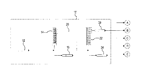
disc filter,
cartridge filter, or bag filter. Fine particle filter 22 is designed to be
ba.ckwashed with filtered
water from the unit. Pneumatic gas assist can be used to dislodge any sticky
material from
the filter surface. Air is compressed with line pressure into a dome on the
device and
expanded when the pressure is relieved during backwash. The backwash
wastewater is
returned to the source of water feed stream 12, e.g., an ocean, via outlet
24.. The water stream
exiting fine particle filter 22 is conditioned cleaning water feed stream 26
which, in some
embodiments, is used in particle and oil removal subsystem 16, chemical oxygen
demand
reduction subsystem 28, heavy metal and dissolved ion removal subsystem 30,
water reuse
17
. . õ
, .õõ - = ....
CA 02865081 2014-08-20
WO 2013/126625
PCT/US2013/027215
subsystem 11.8 and/or oxidizing agent feed stream 94. It should be appreciated
that chemical
and biological oxygen demand levels are reduced by a reduction or removal of
hydrocarbons,
volatile gases, non-volatile gases and .H2S, and that chemical oxygen demand
reduction
subsystem 28 is used to reduce or remove all or some of these contaminants.
[09571 Particle and oil removal subsystem
[00581 Particle and oil removal subsystem 16 receives initial
water feed stream 32
from a plant oil dehydrator, desalter (not shown) or other produced water
generators such as
flow back from a hydrofracturing operation. Feed stream 32 is pumped to gross
particle filter
34 at a pressure of approximately 50 to 150 pounds per square inch gauge
(psig) thereby
removing large particulate matter. In some embodiments of the invention, gross
particle filter
34 is a self-cleaning tubular backwash filter such as the strainers
manufactured by SAMCO
Technologies, Kinney, RP Adams, DOW TequaticTm plus. Gross particle filter 34
is fitted
with a 100-200 micron wedgewire filter element. Other filtration or solids
liquid separation
technologies may also be used for large particulate removal, such as a disc
filter or
Is centrifuge. Gross particle filter 34 is arranged to be baekwashed with
filtered water from the
unit. The backwash wastewater is returned via outlet 36 to the dehydrator or
stilling tank
where solids and attached hydrocarbons settle out and can be removed Is sludge
or
recovered. Depending on the nature of the solids, 'backwash wastewater may be
sent back to
precipitation unit 104, separated and the solids dewatered,
100591 Filtered water 38 from gross particle filter 34 comprises very small
oil
droplets. Filtered water 38 flows to coalescer unit 40 for oil removal. Due to
the small size
of oil droplets, the oil will not separate from filtered water 38 in a
traditional gravity
separator without assistance. Coalescer unit 40 comprises a multi chamber
vessel or pair of
single chamber vessels, designed for either atmospheric or pressure operation.
These units
are custom designed for each application. A suitable coaleseer unit can be
obtained from
SAMCO Technologies located in Buffalo, New York. The first chamber or vessel
holds a
bed of coalescing media. In some embodiments of the invention, the coalescing
media is
Amberliteml ROC110 manufactured by Dow Chemical Company. The coalescing media
attracts the very small oil droplets and allows them to agglomerate into
larger oil droplets that
then float to the top of the water in the second chamber or vessel, similar to
a traditional
gravity separator. The floating oil phase is returned to the dehydrator or
other Suitable
collection device for recovery via outlet 42. Depending on the characteristics
of filtered
18
CA 02865081 2014-08-20
WO 2013/126625
PCT/US2013/027215
water 38 cleaning may be required. Fouling by contaminants such as particles
and paraffin
can occur. Removal of contaminants is accomplished by internal or external
reverse
flow/fluidizing of the coalescing media bed and/or hot water stripping of the
media bed.
Moreover, in some embodiments, coalescer unit 40 may require the use of
additional water,
i.e., conditioned cleaning water feed stream 26. It should be appreciated that
recovery of oil
in coalescer unit 40 may be as high as 95% with residual oil as low as 5 ppm
in the water
stream. In view of the efficiency of the resin separator system, the water
exiting the separator
can be directly discharged to the environment where conditions allow. However,
it should be
appreciated that whether the water is directly discharged or further processed
is based on the
o quality of the feed stream and the discharge standards for the
application or location.
100601 Water feed
44 exiting the separating chamber or vessel of coalescer unit 40 is
transferred to fine particle filter 46 at a pressure of approximately 50 to
150 psig using pump
48, if required, wherein particulate matter with sizes ranging from 10-100
microns is
removed. In some embodiments of the invention, fine particle filter 46 is a
self-cleaning
tubular backwash filter such as the tubular filter manufactured by SAMCO
Technologies.
Fine particle filter 46 is fitted with a 10-50 micron media which may be a
Teflon ,
polypropylene, nylon or metal cloth filter element. Other filtration or solids
liquid separation
technologies may be used for fine particulate removal, such as a disc filter,
cartridge filter, or
bag filter. Fine particle filter 46 is designed to be bacicwashed with
filtered water from the
unit. The backwash wastewater is returned via outlet 50 to the dehydrator or
stilling tank
where solids settle out and can be removed as sludge. Fine particle filter 46
comprises a
dome for trapping and compression of air to allow for pneumatic cleaning
assist
100611 Water stream
52 exiting fine particle filter 46 may containing trace amounts of
free and emulsified oil. Water stream 52 flows to oil removal membrane unit 54
for further
removal of oil. In some embodiments, water stream 52 is transferred to
membrane unit 54
using pump 56. It should be appreciated that depending system needs, only one
of pumps 48
and 56 will be included, e.g., a single pump may be sized to be sufficient for
the needs of the
removal subsystem 16. Oil removal membrane unit 54 is an array of pressure
rated housings
filled with spiral wound or hollow fiber membrane modules, the number and
arrangement of
which are dictated by the water flow rate to yield a permeate water flow rate
of 5-20
gallons/minute/square foot of membrane. In some embodiments of the invention,
the
membrane elements are hydrophilic polyaciylonitrile (PAN) polymer, PVDF, or
PVC. A
19
== --ar- = _ õ_
. õ
CA 02865081 2014-08-20
WO 2013/126625
PCTXS2013/027215
suitable example of a membrane element is General Electric's MW Series
membrane. Feed
water is pressurized to approximately 100-300 psi prior to entering the
membrane array.
Water, dissolved ionic species, and small molecular weight hydrocarbons below
approximately 50K Dalton and approximately 0.01 micron cutoff pass through the
membrane
and are collected as permeate stream 58 resulting in 85% or more of the volume
of the feed
water entering the unit. The remaining water and higher molecular weight above
50K Dalton
molecular weight hydrocarbons are substantially rejected by the membrane and
returned via
outlet 60 to the dehydrator for oil recovery. As oil concentrates in the
membrane separator,
the oil adsorbs BETX compounds thus reducing the COD and BOD in the water. If
the
to membrane requires cleaning, hot water and/or caustic compounds may be
flushed through the
membranes or externally clean the membranes in place within system.
[0062] Chemical
oxygen demand (COD) and biological oxygen demand (BOD)
reduction subsystem
[0063] Chemical
oxygen demand reduction subsystem 28 receives low pressure
permeate stream 58 from oil removal membrane unit 54 Which stream 58 flows to
stripping
unit 62 for removal of volatile organic compounds (VOC) and hydrogen sulfide
(H2S) to
reduce chemical oxygen demand (COD) of the water. Stripping unit 62 is a
conventional
countercurrent gas/liquid contacting tower -filled with random or structured
packing well
blown to those skilled in the art, e.g., Jaeger Tri-Packs or a low profile
tray type. Water
stream 58, rich in VOC and H2S, enters the top of stripping unit 62 and flows
downward
through the packing or trays. Clean atmospheric air stream 64 is introduced
into the bottom
of stripping unit 62 via blower 66 and flows upwardly. As water stream 58
contacts air
stream 64, .VOC and H2S transfer from the liquid phase to the gas phase
yielding vapor phase
stream 68 rich in VOC and 112S. Vapor phase stream 68 exits the top of the
unit, i.e.,
.. stripping unit 62, and water stream 70, lean in VOC and H2S, exits the
bottom of the unit, i.e.,
stripping unit 62. An example of a suitable stripping unit 62 is a convention
tower type
stripping unit such as the stripping unit sold by Delta Cooling Towers, inc.
located in
Rockaway-, New Jersey, or the shallow tray compact type sold by Bisco
Environmental
located in Taunton, Massachusetts.
100641 In some embodiments of the invention, the VOC and H2S rich vapor
phase,
i.e., vapor phase stream 68, flows to gas flare 72. Gas flare 72 is also
commonly known in
the art as a flare and a flare stack, and may, in some embodiments, be a
thermal oxidizer. In
. . .õ . õ.õ.... .õ .
õ
CA 02865081 2014-08-20
WO 2013/126625 PCT/1JS2013/027215
some embodiments of the invention, vapor phase stream 68 flows to bio scrubber
unit 74 for
treatment, e.g., reducing carbon content, to allow discharge to atmosphere
meeting regulatory
limits. In some embodiments of the invention, No scrubber unit 74 is a
conventional
contacting tower tilled with BioVasilm or NIP2C, a porous, hydrophilic, high
surface area
flow through ceramic packing manufactured by CerMediaml lefeC located in
Buffalo, New
York, The media provides high surface area and flow throughput for the air,
which provides
increased contact with microorganisms that are generally indigenous to the
region where the
unit resides and may include any species of heterotrophic bacteria that
inoculate the media
and adapt to destroy, in an aerobic process, VOCs and II2S. Biofihers are
reactors in which
waste gases are allowed to pass through a porous packed bed material
immobilized with
suitable microbial cultures. As the waste gas passes through the filter
medium, the
contaminants in the gas transverse to the liquid phase surrounding the
microbial biofilm in
the medium where they are degrade to CO2, t20, SO4, inorganic salts and
biomass by
microorganisms. The high surface area of the media permits the unit to have a
small overall
footprint and low weight.
[0065] Conditioned cleaning water stream 26, obtained from. an ocean or
other
available clean water source as described supra, is trickled across the top of
the packing
material for humidity and water wetting control. Water stream 26 is sprayed
over the
packing material at a rate necessary to maintain saturated- packing material
while flushing
away treated byproducts. Packing material size is selected to cause an empty
bed contact of
between 5 ¨ 60 seconds. VOC and HiS rich vapor, i.e.., vapor phase stream 68,
flows into the
bottom of the tower of bi.o scrubber unit 74 and upwardly through the packing
material. The
preferred packing material is a very porous ceramic media which has extremely
high surface
area. The surface of the packing material is covered with a biotilm of
naturally occurring
.. microorganisms that metabolize VOCs and 112S to carbon dioxide, water, and
sulfates which
can be safely discharged to the atmosphere or ocean. There are many types of
naturally
occurring bacteria that provide biochemical destruction of VOCs and }LS.
Examples include
but are not limited to chemoheterotophic bacteria and sulfur oxidizing
bacteria. Water stream
76 is discharged to an ocean or other suitable discharge location and treated
air stream 78 is
discharged to the atmosphere.
10066] Water stream 70, Which exits from the bottom of stripping unit
62, flows to
hydrocarbon polishing unit 80 for removal of dissolved, non-volatile organic
compounds,
21
CA 2,865,081
CPST Ref: 11508/00001
e.g., phenols and polycyclic aromatic hydrocarbons (PHA), to recover
additional hydrocarbons and to
further reduce COD of water stream 70 to make it suitable for disposal or
reuse. In some embodiments,
water stream 70 is transferred to polishing unit 80 using pump 82. In some
embodiments of the invention,
hydrocarbon polishing unit 80 comprises two standard ASME pressure vessels
filled with synthetic
adsorbent resin. The pressure vessels may be arranged in various series and
parallel configurations. An
example of a suitable synthetic adsorbent resin is the styrene-DVB macroporous
material DowexTM
OptiporeTM L493 manufactured by Dow Chemical Company located in Midland,
Michigan. Other
adsorptive media such as activated carbon, e.g., activated carbon sold by
Calgon Carbon located in
Pittsburgh, Pennsylvania, may be utilized in hydrocarbon polishing unit 80.
During normal service, the
vessels that form hydrocarbon polishing unit 80 are arranged in series or
parallel with the first vessel
removing the largest portion, and possibly all, of the COD load from water
stream 70, with the second
vessel acting as a polishing unit for any trace materials passing through the
first vessel. As water stream
70 flows through the adsorbent, i.e., synthetic adsorbent resin, dissolved non-
volatile organic compounds
transfer to and are bound to active sites on the adsorbent surface while
treated water stream 84, having COD
levels meeting discharge limits, exits hydrocarbon polishing unit 80 via
outlet 88.
[0067] In some embodiments of the invention, the synthetic adsorbent
resin used in hydrocarbon
polishing unit 80 can be regenerated. During a regeneration event, one vessel
remains online treating water
stream 70 while the other vessel is regenerated. The vessel to be regenerated
is taken offline and the
saturated synthetic adsorbent resin is contacted with 50-150 psig steam 87 to
desorb the bound organics.
Vapor containing the desorbed organic material exits the vessel being
regenerated and is then condensed
and recycled to the dehydrator for recovery via outlet 88. It should be
appreciated that in some
embodiments, all hydrocarbons are recovered in polishing unit 80 thereby
eliminating the need to include
stripping unit 62, gas flare 72 and bio filter scrubber unit 74.
[0068] Heavy metals and dissolved ion removal subsystem
[0069] Heavy metals removal subsystem 30 receives water stream 84 exiting
hydrocarbon
polishing unit 80 contains dissolved heavy metal ions, such as lead, copper,
cadmium, mercury, barium and
strontium, and other ions such as boron which must be removed to a level
suitable for discharge, e.g.,
discharge in an ocean. In some embodiments
CPST Doc: 303413.1 22
Date Recue/Date Received 2020-11-02
õ
CA 02865081 2014-08-20
WO 2013/126625
PCT/US2013/027215
of the invention, heavy metals and dissolved ion removal unit 90 comprises two
standard
ASME pressure vessels filled with ion exchange resin such as AniberliteIm
IRA748,
Ambe.rsepTM 6T74 or AmbcriiteTM 1RA743 (for boron removal), all sold by Dow
Chemical
Company located in Midland, Michigan. Other ion exchange resins may be used,
i.e., ion
exchange resins designed for selective removal of trace metal compounds from
high salinity
solutions. During normal service, the vessels are arranged in series with the
first vessel
removing the largest portion, and possibly all, of the heavy metals and/or
dissolved ions load
from water stream 84 with the second vessel acting as a polishing unit for any
trace material
passing through the first vessel. It should be appreciated that vessels may
also be arranged in
parallel depending on the needs of the system, spatial constraints, etc. As
water stream 84
flows through the ion exchange resin bed, dissolved heavy metal ions and other
dissolved
ions transfer to and are bound to active sites on the adsorbent surface of the
ion exchange
resin material While treated water stream 92, having contaminant levels
meeting discharge
limits, exits heavy metals and dissolved ion removal unit 90. Treated water
stream 92 is
blended with oxidizing agent feed stream 94, which may include oxidizing
agents such as
chlorine, ozone or hydrogen peroxide, for trace COD removal and /-1.2S
destruction, after
which treated water stream 92 is discharged, e.g., discharged to an ocean via
outlet 96.
Alternatively, treated water stream 92 can be further treated for use in the
water recovery
stream for enhanced oil recovery (E0R), desalting and hydrofracturing
operations as
described infra.
100701 In some
embodiments of the invention, the ion exchange resin used in heavy
metals and dissolved ion removal unit 90 can be regenerated. During a
regeneration event,
one vessel remains online treating water stream 84 while the other vessel is
being
regenerated. The vessel to be regenerated is taken offline and saturated ion
exchange resin is
contacted with concentrated acidic stream 98, e.g., sulfuric or hydrochloric
acid, to desorb the
heavy metals and other dissolved ions such as boron. The ion exchange resin is
then
contacted with concentrated basic stream 100, e.g., sodium hydroxide, to
restore exchange
capacity to the ion exchange resin. Some resins, e.g., AnibersepTM 0T74, do
not require the
sodium hydroxide restoratioustep.
[0071] Regeneration solutions stream 102 exiting the ion exchanged resin
bed of
heavy metals and dissolved ion removal -Unit 90 is rich in heavy metals, and
is collected for
subsequent processing in heavy metals and dissolved ion precipitation unit
104.
23
õ = .
CA 02865081 2014-08-20
WO 2013/126625
PCT/US2013/027215
Concentrated basic stream 106, e.g., sodium hydroxide or calcium hydroxide
(lime),is added
to regeneration solutions stream 102 to adjust the pH of stream 102 to the
appropriate range
for heavy metal precipitation as insoluble metal hydroxides. ln some
embodiments of the
invention, the metal hydroxide precipitate and dissolved ion precipitate is
transferred from
precipitation unit 104 to filter press 108 -using pump 110. The metal
hydroxide precipitate is
filtered from regeneration solutions stream 102 using filter press 108, i.e.,
a standard filter
press well known to those skilled in the art. Alternative solid/liquid
separating devices, such
as a centrifuge, may also be used. Precipitated solids cake 112 are collected
for offsite
disposal. Filtrate stream 114 is recycled to heavy metals and dissolved ion
removal unit 90
while final filtered waste water stream. 116 may be returned to the dehydrator
or discharged.
[0072] Water reuse subsystem
[0073] In many applications it is advantageous to utilize produced
water as a supply
for EOR and other production operations. For EOR operations, pressurized water
is injected
into an oil reservoir to increase reservoir pressure and oil output. Water
used for this purpose
must have low concentrations of sulfate, salts contributing to hardness,
metals, boron, TDS
and oxygen which otherwise would degrade the oil or yield high concentration
of H2S, react
with down hole chemistry, or plug the oil recovery collection system in
recovered oil or
natural gas. In some embodiments, water reuse subsystem 118 is used to prepare
water for
subsequent EOR operations, hydrofracturing. or other production activities. It
should be
appreciated that "TDS÷ is intended to include but not be limited to salts that
contribute to
water hardness.
[0074] hi some embodiments of the invention, water stream 92
exiting heavy metals
and dissolved ion removal unit 90 flows to sulfate and hardness removal
membrane unit 120.
Sulfate and hardness removal membrane unit 120 comprises an array of pressure
rated
housings tilled with spiral wound .nanotiltration membrane modules, the number
and
arrangement of which are dictated by the flowrate of water stream 92 needed to
yield a
permeate water flowrate of 10-15 galionslminute/square foot of membrane. In
some
embodiments of the -invention, the membrane elements are FilmtecTm SR90 sold
by Dow
Chemical Company located in Midland, Michigan. Water stream 92 is pressurized
to 100-
300 psi prior to entering the membrane array of sulfate and hardness removal
membrane unit
1.20 using pump 122. Water and some dissolved ionic species, namely sodium and
chloride
ions, pass through the membrane and are collected as permeate water stream 124
amounting
24
_
CA 02865081 2014-08-20
WO 2013/126625
PCT/US2013/027215
to 75-85% volume of water stream 92 entering unit 120. The remaining water and
higher
molecular weight ions, e.g., divalents such as sulfate and hardness, are
rejected by the
membrane array and are discharged to the ocean via outlet 126.
100751 In some
embodiments, low TDS water is required for various operations, e.g.,
EOR, desalting and/or hydrofracturing. As described above, low TDS water is
produced
using high pressure, high rejection reverse osmosis membranes. In these
embodiments,
permeate water stream 1.24 flows to TDS removal unit 128. TDS removal unit 128
comprises
high pressure, high rejection reverse osmosis membrane elements, e.g., Filmtec
TM SW30 sold
by Dow Chemical located in Midland, Michigan. Permeate water stream 124 is
pressurized
to to 700-1500 psi prior to entering the membrane array by a high pressure
pump integnal to or
incorporated within TDS removal unit 128. The membrane rejects low weight
ionic
compounds like sodium and chloride. Water stream 129, i.e., water collected
from permeate
water stream 124, amounts to 30-70% volume of the feed water entering TDS
removal unit
128. The remaining water and lower molecular weight ions such as sodium, i.e.,
waste
stream 130, the material rejected by the membranes, are discharged to the
ocean or other
suitable receiving body via outlet 131. Where feasible, the high pressure,
Le., energy, of
waste stream 1.30 can be recovered using an energy recovery device and
returned to the feed
stream through reduction of power to the main feed pump. Suitable energy
recovery units.
include but are not limited to work exchangers and turbines, e.g., DWEERTm and
Calder ERT
sold by Flowseive located in Irving, Texas.
[0076] After sulfate
removal, permeate water stream 129 flows to oxygen removal
unit 132. Oxygen removal unit 132 comprises an array of pressure rated
housings filled with
gas permeable hollow fibers or spiral wound, the number and arrangement of
which are
dictated by the .flowrate of water stream 129 needed to maintain pressure loss
at less than 25
psi and to reduce oxygen concentration from saturation to less than 50-100
PPB. In some
embodiments of the invention, the membrane elements are Liqui-Cel membrane
contactors as
sold by Membrana located in Wuppertal, Germany, or alternatively, may be MDS-
32502 as
sold by Membrane Development Specialist located in Solana, California. h has
been found
that the spiral wound configuration of MDS-32502 is easily cleaned. A booster
pump
integral to or incorporated within oxygen removal unit 132 boosts water stream
129 to 50-
150 psi prior to entering the membrane array. Water and dissolved gases,
namely oxygen,
flow through the shell side of the contactor. A liquid ring vacuum pump pulls
a 50 tor
CA 2,865,081
CPST Ref: 11508/00001
vacuum on the tube side to drive gas transfer from the liquid to the gas phase
across the membrane.
Additionally, nitrogen gas stream 134 from a pressure or thermal swing
nitrogen generator flows through
the hollow fibers to lower oxygen partial pressure and further drive oxygen
from the liquid phase to the gas
phase. Sweep gas stream 136 is discharged to atmosphere 138 via vacuum pump
140.
[0077] Deoxygenated water stream 142 may be further polished with the use
of an catalytic
reaction in pressurized vessel 144. As described supra, pressurized vessel 144
is filled with a palladium-
doped resin. Deoxygenated water stream 142 receives pressurized hydrogen
stream 146 which is dissolved
therein. Subsequently, the water stream passes through the resin bed and exits
as deoxygenated water
stream 148. Suitable resins include Lewatit0 K 3433 (a crosslinked polystyrene
resin with tertiary amine
functional groups) sold by Lenntech by located in Rotterdam, Netherlands. It
should be appreciated that in
some embodiments, oxygen may be removed from feed water 129 by using an ion
exchange resin.
[0078] Deoxygenated water stream 148, which may be blended with oxygen
scavenger stream 150
such as hydrazine to further reduce dissolved oxygen concentration below 5
PPB, is then sent to EOR
injection equipment for subsequent use via outlet 152.
[0079] The present invention provides: hydrocarbon recovery, compact
layout; light weight
overall structure; minimum chemical use; and, minimum waste generation. Unique
aspects of the present
invention include but are not limited to: use of a resin for oil removal in
conjunction with a membrane; use
of small foot print filters staged around the resin unit; an air striper with
bio filter for volatile organic
compounds and H25 removal; an air striper with COD resin trap; a heavy metals
removal unit in place of
conventional precipitation; blending with a sea, fresh or treated water waste
stream; water conditioned for
use in hydrofracturing, desalting and EOR having high or low TDS; use of
degasification membranes; and,
degasification membranes in combination with resin degasification.
[0080] It will be appreciated that various of the above-disclosed and
other features and functions,
or alternatives thereof, may be desirably combined into many other different
systems or applications.
Various presently unforeseen or unanticipated alternatives, modifications,
variations or improvements
therein may be subsequently made by those skilled in the art.
CPST Doc: 303413.1 26
Date Recue/Date Received 2020-11-02