Note: Descriptions are shown in the official language in which they were submitted.
CA 02865632 2016-05-26
AIRCRAFT ELECTRIC MOTOR SYSTEM
BACKGROUND INFORMATION
The present disclosure relates generally to aircraft
and, in particular, to aircraft with electric motors.
Still more particularly, the present disclosure relates
to a method and apparatus for an aircraft electric motor
system.
An electric motor is a device that converts
electrical power into mechanical power. Electric motors
are used for various applications. These applications
include fans, pumps, tools, disc drives, drills, and
other types of devices that may be found in different
types of platforms.
An example of a platform in which an electric motor
may be used is an aircraft. In some cases, the electric
motor may be part of a propulsion system for the
aircraft. For example, the electric motor may turn one
or more propellers for the aircraft to provide movement
of the aircraft on the ground, through the air, or a
combination thereof.
An aircraft that uses the electric motor may take
various forms. For example, the aircraft may be an
airplane, a rotorcraft, a helicopter, a guadcopter, an
unmanned aerial vehicle, or some other suitable type of
aircraft.
When electric motors are used for propulsion of the
aircraft, electrical energy may be supplied by a power
source. For instance, electrical energy may be supplied
using a battery system. The load on the battery system
or other power source is an important consideration for
the design and manufacturing of the aircraft. For
example, the amount of electrical energy used by the
1
CA 02865632 2016-05-26
electric motor to move the aircraft during various stages
of flight may be important.
Electric motors that use battery systems may require
the battery to be recharged after a specified amount of
time, distance, electrical energy use, or a combination
thereof. If the electric motor uses more electrical
energy than desired for a desired level of performance,
then the time, distance, or time and distance between
recharging and maintenance may be shorter than desired.
Therefore, it would be desirable to have a method and
apparatus that take into account at least some of the
issues discussed above, as well as other possible issues.
SUMMARY
In one illustrative embodiment, an apparatus
comprises a controller. The controller is configured to
identify a state for an electric aircraft. The
controller is further configured to identify a group of
recharging parameters for a group of electric motors in
an electric propulsion system. The electric propulsion
system is configured to move the electric aircraft based
on the state for the group of electric motors for the
electric aircraft. The controller is still further
configured to recharge a power source for the electric
aircraft using the group of recharging parameters to
control recharging of the power source with the group of
electric motors when a recharge state is present for the
electric aircraft.
In another illustrative embodiment, an electric
aircraft comprises an airframe, a group of propellers, a
group of electric motors physically associated with the
airframe, a power source, and a controller. The group of
electric motors is configured to turn the group of
2
propellers and move the airframe. The power source is
connected to the group of electric motors such that a
current flows between the power source and the group of
electric motors. The controller is configured to
identify a state for the group of electric motors. The
controller is further configured to identify a group of
recharging parameters for the group of electric motors
when the state is a recharge state present for the
electric aircraft. The controller is still further
configured to recharge the power source using the group
of recharging parameters to control recharging of the
power source with the group of electric motors when the
recharge state is present for the electric aircraft.
In yet another illustrative embodiment, a method for
controlling an electric aircraft is provided. A state
for the electric aircraft is identified. A group of
recharging parameters is identified for a group of
electric motors when the state is a recharge state and is
present for the electric aircraft. The group of electric
motors is configured to move the electric aircraft. A
power source for the electric aircraft is recharged using
the group of recharging parameters to control recharging
of the power source with the group of electric motors
when the recharge state is present for the electric
aircraft.
In yet another illustrative embodiment an apparatus
comprises a motor; a power source; a switch bridge
connected to the motor; a voltage controller connected to
the switch bridge and the power source; and a four-
quadrant motor controller programmed to: control the
voltage controller to control a voltage provided from the
power source to the switch bridge during an operating
state; control the switch bridge to control a current
provided to the motor during the operating state; control
3
CA 2865632 2019-01-15
the switch bridge to control a current provided from the
motor during a recharge state; and control the voltage
controller to control a voltage provided to the power
source to charge the power source during the recharge
state.
In yet another illustrative embodiment an electric
aircraft comprises an airframe; a propeller; a motor
physically associated with the airframe and configured to
turn the propeller and move the airframe; a power source;
a switch bridge connected to the motor; a voltage
controller connected to the switch bridge and the power
source; and a four-quadrant motor controller programmed
to: control the voltage controller to control a voltage
provided from the power source to the switch bridge
during an operating state; control the switch bridge to
control a current provided to the motor during the
operating state; control the switch bridge to control a
current provided from the motor during a recharge state;
and control the voltage controller to control a voltage
provided to the power source to charge the power source
during the recharge state.
In yet another illustrative embodiment a method
comprises controlling a voltage controller to control a
voltage provided from a power source to a switch bridge
during an operating state; controlling the switch bridge
to control a current provided to a motor during the
operating state; controlling the switch bridge to control
a current provided from the motor during a recharge
state; and controlling the voltage controller to control
a voltage provided to the power source to charge the
power source during the recharge state.
4
CA 2865632 2019-01-15
In yet another illustrative embodiment an electric
aircraft comprises a power source; an electric propulsion
system configured to move the electric aircraft, the
electric propulsion system comprising a group of electric
motors and a group of propellers; and a controller
configured to: control a group of motor controllers, each
motor controller controlling one of the electric motors
and comprising a power inverter connected to the motor,
and a voltage controller connected to the power inverter
and the power source, each motor controller configured to
send commands to the voltage controller and power
inverter, each of the motor controllers being configured
to: control the voltage controller to regulate the
voltage applied to the electric motor in an operating
state and regulate the voltage applied to the power
source during a recharge state; and control the power
inverter to send current to the electric motor when the
electric motor is in the operating state and to receive
current from the electric motor when the electric motor
is in the recharge state.
In yet another illustrative embodiment a method
comprises controlling a voltage controller to regulate a
voltage applied to an electric motor in an operating
state and regulate the voltage applied to a power source
during a recharge state; and controlling a power inverter
to send current to the electric motor when the electric
motor is in the operating state and to receive current
from the electric motor when the electric motor is in the
recharge state.
5
CA 2865632 2019-01-15
In yet another illustrative embodiment an electric
aircraft comprises an airframe; a power source; an
electric propulsion system configured to move the
electric aircraft, the electric propulsion system
comprising a group of electric motors and a group of
propellers; an energy-harvesting system configured to
recharge the power source, the energy-harvesting system
comprising the group of electric motors and the group of
propellers; and a controller configured to: identify a
state for the electric aircraft; identify a group of
recharging parameters for the group of electric motors
based on the state for the electric aircraft; recharge
the power source for the electric aircraft using the
group of recharging parameters to control recharging of
the power source with the group of electric motors when a
recharge state is present for the electric aircraft;
control a group of motor controllers, each motor
controller controlling a motor and comprising a power
inverter connected to the motor, and a voltage controller
connected to the power inverter and the power source,
each motor controller configured to send commands to the
voltage controller and the power inverter, each of the
motor controllers being configured to: control the
voltage controller to regulate the voltage applied to the
electric motor in an operating state and regulate the
voltage applied to the power source during the recharge
state; and control the power inverter to send current to
the electric motor when the electric motor is in the
operating state and to receive current from the electric
motor when the electric motor is in the recharge state.
Sa
CA 2865632 2019-01-15
In still yet another illustrative embodiment a
method for controlling an electric aircraft comprises
identifying a state for the electric aircraft;
identifying a group of recharging parameters for a group
of electric motors when the state is a recharge state and
is present for the electric aircraft, wherein the group
of electric motors is configured to move the electric
aircraft; recharging a power source for the electric
aircraft using the group of recharging parameters to
control recharging of the power source with the group of
electric motors when the recharge state is present for
the electric aircraft; controlling a voltage controller
to regulate a voltage applied to an electric motor of the
group of electric motors in an operating state and
regulate the voltage applied to the power source during
the recharge state; and controlling a power inverter to
send current to the electric motor when the electric
motor is in the operating state and to receive current
from the electric motor when the electric motor is in the
recharge state.
The features and functions can be achieved
independently in various embodiments of the present
disclosure or may be combined in yet other embodiments in
which further details can be seen with reference to the
following description and drawings.
5b
CA 2865632 2019-01-15
BRIEF DESCRIPTION OF THE DRAWINGS
The novel features believed characteristic of the
illustrative embodiments are set forth in the appended
claims. The illustrative embodiments, however, as well
as a preferred mode of use, further objectives and
features thereof, will best be understood by reference to
the following detailed description of an illustrative
embodiment of the present disclosure when read in
conjunction with the accompanying drawings, wherein:
Figure 1 is an illustration of an electric aircraft
environment in accordance with an illustrative
embodiment;
Figure 2 is an illustration of a block diagram of an
electric aircraft in accordance with an illustrative
embodiment;
Figure 3 is an illustration of a block diagram of a
state machine for operation of an electric aircraft in
accordance with an illustrative embodiment;
Sc
CA 2865632 2019-01-15
CA 02865632 2016-05-26
Figure 4 is an illustration of an information flow
diagram for an electric motor system in accordance with
an illustrative embodiment;
Figure 5 is an illustration of another information
flow diagram for an electric motor system in accordance
with an illustrative embodiment;
Figure 6 is an illustration of an information flow
diagram for an electric motor in an operating state in
accordance with an illustrative embodiment;
Figure 7 is an illustration of an information flow
diagram for an electric motor in a recharge state in
accordance with an illustrative embodiment;
Figure 8 is an illustration of a block diagram of a
power source and a current controller in accordance with
an illustrative embodiment;
Figure 9 is an illustration of equations for
calculating a commanded current in accordance with an
illustrative embodiment;
Figure 10 is an illustration of a circuit diagram of
a voltage controller and a power inverter for an electric
motor in accordance with an illustrative embodiment;
Figure 11 is an illustration of a current flow
through a voltage controller in accordance with an
illustrative embodiment;
Figure 12 is an illustration of a current flow
through a voltage controller in accordance with an
illustrative embodiment;
Figure 13 is an illustration of a voltage controller
and a power inverter in accordance with an illustrative
embodiment;
Figure 14 is an illustration of a reverse current
flow through a voltage controller and a power inverter in
accordance with an illustrative embodiment;
6
CA 02865632 2016-05-26
Figure 15 is an illustration of a voltage controller
and a power inverter in accordance with an illustrative
embodiment;
Figure 16 is an illustration of four-quadrant
control in accordance with an illustrative embodiment;
Figure 17 is an illustration of a flowchart of a
process for controlling an electric aircraft in
accordance with an illustrative embodiment;
Figure 18 is an illustration of a data processing
system in the form of a block diagram in accordance with
an illustrative embodiment;
Figure 19 is an illustration of a block diagram of
an aircraft manufacturing and service method in
accordance with an illustrative embodiment; and
Figure 20 is an illustration of a block diagram of
an aircraft in accordance with an illustrative
embodiment.
DETAILED DESCRIPTION
The illustrative embodiments recognize and take into
account one or more different considerations. For
example, the illustrative embodiments recognize and take
into account that the time, distance, or both time and
distance that an aircraft may fly using an electric motor
may be increased in a number different ways. For
instance, when the electric motor uses a battery system
as a power source, that battery system may be recharged.
The illustrative embodiments further recognize and take
into account that this recharging of the battery system
may occur while the aircraft is away from a designated
recharging location for the aircraft.
Illustrative embodiments recognize and take into
account that electric motors for aircraft may include an
7
CA 02865632 2016-05-26
energy-harvesting device. The energy-harvesting device
may generate electrical energy to recharge the battery
system while the aircraft is away from a designated
recharging location for the aircraft. In this
illustrative example, the energy-harvesting device may
take various forms. For instance, the energy-harvesting
device may be selected from one of a solar cell, a
thermoelectric generator, a piezoelectric crystal, an
antenna, and other suitable types of devices configured
to recharge the battery system of the aircraft.
The illustrative embodiments further recognize and
take into account that the addition of an energy-
harvesting device as a separate component in the aircraft
may add more weight and complexity than desired in some
cases. The illustrative embodiments further recognize
and take into account that an electric motor used for
propulsion of an aircraft may also be used as an energy-
harvesting device. In particular, the electric motor in
conjunction with a propeller may be used to harvest wind
energy available in the form of kinetic energy to
generate a current that may be used to recharge a battery
system in the aircraft. The illustrative embodiments
recognize and take into account, however, that some
currently used propulsion systems may not have the
capability to provide both movement and recharging for
the aircraft.
Thus, the illustrative embodiments provide a method
and apparatus for recharging a power source. In one
illustrative example, an apparatus comprises a
controller. The controller is configured to identify a
state for an aircraft and identify a group of recharging
parameters for a number of electric motors. The number
of electric motors is configured to move the aircraft
through the air when a recharge state is present for the
8
CA 02865632 2016-05-26
aircraft. The controller is further configured to
recharge a power source for the aircraft using the group
of parameters and control recharging of the power source
with the group of electric motors when the recharge state
is present for the aircraft.
With reference now to figures and, in particular,
with reference to Figure 1, an illustration of an
electric aircraft environment is depicted in accordance
with an illustrative embodiment. In this illustrative
example, electric aircraft environment 100 is an example
of an environment in which electric aircraft 101 may
operate.
In this illustrative example, electric aircraft 101
takes the form of quadcopter 102. Quadcopter 102 is a
type of aircraft that is lifted and propelled by four
sets of propellers in this illustrative example. In this
illustrative example, a "set" includes one or more
components. Accordingly, a set of propellers includes
one or more propellers.
As depicted, quadcopter 102 flies using electric
propulsion system 104 and performs different operations
in electric aircraft environment 100. For example,
quadcopter 102 may perform operations for a surveillance
mission. The operations for the surveillance mission may
include generating images of objects including building
106. These images may be still images, video, or some
combination thereof.
Additionally, the surveillance mission also may
include generating images of traffic on road 108. For
example, quadcopter 102 may generate images of vehicle
110 moving on road 108.
In these illustrative examples, quadcopter 102 is
configured to fly for a selected period of time. The
time of flight for quadcopter 102 is based on the
9
CA 02865632 2016-05-26
capacity of the power source in quadcopter 102 and its
required performance level. In this illustrative
example, the performance level may include the level of
energy needed to perform a mission as desired. As a
result, quadcopter 102 may return to recharging location
112 after some period of time to recharge the power
source for quadcopter 102. For instance, quadcopter 102
may return to recharging location 112 to recharge a
battery system for quadcopter 102.
In some cases, it may be desirable to extend the
mission time for quadcopter 102. In other words, it may
be desirable to use an amount of energy that allows
quadcopter 102 to fly for a longer period of time,
generate more information about electric aircraft
environment 100, perform additional operations, or some
combination thereof.
The mission time for quadcopter 102 may be extended
in a number of different ways. For example, quadcopter
102 may rest on a structure in electric aircraft
environment 100 for a period of time while performing the
mission.
In one illustrative example, quadcopter 102 may use
roof 114 as a vantage point, using less power to perform
a portion of a mission while on roof 114. For instance,
roof 114 may be a location from which quadcopter 102 may
generate images of vehicle 110 moving on road 108 without
flying along road 108. In this manner, quadcopter 102
may save battery life and extend mission time.
In another illustrative example, quadcopter 102 may
extend mission time by using an energy-harvesting system
to recharge the power source. In particular, quadcopter
102 may employ an energy-harvesting system that has dual
use. In other words, the energy-harvesting system may
CA 02865632 2016-05-26
perform another function in addition to recharging the
power source.
As depicted in this example, electric propulsion
system 104 may also function as an energy-harvesting
system to recharge the power source of quadcopter 102.
The energy-harvesting system for quadcopter 102 may be
activated in a number of different ways. For instance,
quadcopter 102 may land on air conditioning unit 116.
As illustrated, air flowing from air conditioning
unit 116 may turn propellers 118 to generate electrical
energy that may be used to recharge the power source in
quadcopter 102. In this manner, electric propulsion
system 104 may have a dual purpose as an energy-
harvesting system and therefore, a separate energy-
harvesting system may not be needed in quadcopter 102.
As a result, at least one of weight, complexity, or other
factors may be reduced for quadcopter 102 in these
illustrative examples.
As used herein, the phrase "at least one of," when
used with a list of items, means different combinations
of one or more of the listed items may be used and only
one of each item in the list may be needed. For example,
"at least one of item A, item B, or item C" may include,
without limitation, item A, item A and item B, or item B.
This example also may include item A, item B, and item C
or item B and item C. Of course, any combinations of
these items may be present. In other examples, "at least
one of" may be, for example, without limitation, two of
item A, one of item B, and ten of item C; four of item B
and seven of item C; and other suitable combinations.
The item may be a particular object, thing, or a
category. In other words, at least one of means any
combination of items and number of items may be used from
11
CA 02865632 2016-05-26
the list but not all of the items in the list are
required.
In other illustrative examples, quadcopter 102 may
land on another structure with a suitable amount of wind
in the environment around the structure. For instance,
quadcopter 102 may land on roof 114 such that its
propellers face in the direction of the relative wind
vector. This wind may then be used to recharge the power
source of quadcopter 102.
The illustration of electric aircraft environment
100 in Figure 1 is only meant as an example of an
implementation for an illustrative embodiment. In other
illustrative examples, one or more electric aircrafts may
be used in addition to or in place of quadcopter 102.
In other examples, missions may be performed in
other locations other than the location of building 106.
For example, missions may be performed to survey a
pipeline, obtain information about a forest fire, and
other suitable types of missions.
With reference now to Figure 2, a block diagram of
an electric aircraft is depicted in accordance with an
illustrative embodiment. Quadcopter 102 in Figure 1 is
an example of one physical implementation of electric
aircraft 200 shown in block form in Figure 2.
In this illustrative example, electric aircraft 200
includes a number of components. As depicted, electric
aircraft 200 includes airframe 202, electric propulsion
system 204, energy-harvesting system 206, power source
208, and controller 210. Electric aircraft 200 may have
other components in addition to or in place of the ones
depicted in the different illustrative examples.
As illustrated, airframe 202 is the mechanical
structure for electric aircraft 200. Airframe 202 may be
selected from at least one of a frame, a fuselage, or
12
CA 02865632 2016-05-26
some other physical structure that may be associated with
other components within electric aircraft 200.
When one component is "associated" with another
component, the association is a physical association in
the depicted examples. For example, a first component
may be considered to be physically associated with a
second component by at least one of being secured to the
second component, bonded to the second component, mounted
to the second component, welded to the second component,
fastened to the second component, or connected to the
second component in some other suitable manner. The
first component also may be connected to the second
component using a third component. The first component
may also be considered to be physically associated with
the second component by being formed as part of the
second component, extension of the second component, or
both.
As depicted, electric propulsion system 204 includes
group of propellers 212 and group of electric motors 214.
As used here, a "group of" when used with reference to
items means one or more items. For example, group of
propellers 212 is one or more propellers.
In this illustrative example, group of propellers
212 are physically associated with group of electric
motors 214. Group of electric motors 214 is physically
associated with airframe 202.
Group of electric motors 214 is configured to turn
group of propellers 212 and move airframe 202 for
electric aircraft 200. The movement of electric aircraft
200 by electric propulsion system 204 may be on the
ground, in the air, or a combination thereof.
In this illustrative example, energy-harvesting
system 206 also includes group of propellers 212 and
group of electric motors 214. In other words, group of
13
CA 02865632 2016-05-26
propellers 212 and group of electric motors 214 may
function as either electric propulsion system 204 or
energy-harvesting system 206 in this illustrative
example.
As depicted, power source 208 is connected to group
of electric motors 214 such that current 216 flows
between power source 208 and group of electric motors
214. In this illustrative example, power source 208 is
battery system 209. In other illustrative examples,
power source 208 may be selected from one of a fuel cell
and other suitable types of rechargeable power sources.
Battery system 209 is comprised of group of
batteries 218 and other suitable components configured to
operate battery system 209. For instance, in some
illustrative examples, battery system 209 may comprise a
battery balancer circuit configured to monitor the charge
state of one or more batteries in battery system 209. In
other illustrative examples, this battery balancer
circuit may be absent from battery system 209.
In this depicted example, current 216 flows from
power source 208 to group of electric motors 214 when
group of propellers 212 and group of electric motors 214
function as electric propulsion system 204. Current 216
flows from group of electric motors 214 to power source
208 when group of propellers 212 and group of electric
motors 214 function as energy-harvesting system 206 to
recharge power source 208.
In this illustrative example, the recharging of
power source 208 may take the form of parasitic
recharging. Current 216 may be a regenerative current
when current 216 flows from group of electric motors 214
to power source 208.
In this illustrative example, a parasitic recharge
refers to the process of extracting energy from a non-
14
CA 02865632 2016-05-26
conventional power source. In other words, parasitic
recharge comes from a source whose primary function is
not to provide power. For instance, when energy-
harvesting system 206 uses the mechanical energy in the
wind coming out of the exhaust of an air conditioning
unit to charge power source 208, the process may be
referred to as parasitic recharge.
In this illustrative example, controller 210 is
configured to control operation of electric aircraft 200.
As depicted, controller 210 may be implemented in
software, hardware, firmware, or a combination thereof.
When software is used, the operations performed by
controller 210 may be implemented in a program code
configured to run on a processor unit. When firmware is
used, the operations performed by controller 210 may be
implemented in the program code and data and stored in
persistent memory to run on a processor unit. When
hardware is employed, the hardware may include circuits
that operate to perform the operations in controller 210.
In this illustrative examples, the hardware may take
the form of a circuit system, an integrated circuit, an
application specific integrated circuit (ASIC), a
programmable logic device, or some other suitable type of
hardware configured to perform a number of operations.
With a programmable logic device, the device may be
configured to perform the number of operations. The
device may be reconfigured at a later time or may be
permanently configured to perform the number of
operations.
Examples of programmable logic devices include, for
example, a programmable logic array, a programmable array
logic, a field programmable logic array, a field
programmable gate array, and other suitable hardware
devices. Additionally, the processes may be implemented
CA 02865632 2016-05-26
in organic components integrated with inorganic
components and may be comprised entirely of organic
components excluding a human being. For example, the
processes may be implemented as circuits in organic
semiconductors.
In the illustrative example, controller 210 may be
an impulse width modulation controller (IWMC). In this
depicted example, an impulse width modulation controller
controls the current in the windings of a direct current
(DC) motor using impulse width modulation (IWM). Impulse
width modulation is a digital algorithmic method that
provides four quadrant control of current within the
motor windings with an "H" bridge switching
configuration. This "H" bridge also may be referred to
as a power inverter in these illustrative examples.
During each duty cycle, feedback determines the
appropriate time for one switch bridge switch to be on or
off in order to provide a desired positive or negative
change of current. By varying the duty cycle, the
magnitude of current 216 is affected to drive current 216
closer to a desired level. In other illustrative
examples, other types of controllers may be used for
controller 210, depending on the particular
implementation.
In this depicted example, controller 210 is
configured to identify state 220 for group of electric
motors 214. State 220 may be an operational state in
these illustrative examples. For instance, state 220 may
be selected from one of operating group of electric
motors 214, recharging group of electric motors 214,
standby, or some other suitable state.
Controller 210 is also configured to identify group
of recharging parameters 222 for group of electric motors
214 in electric propulsion system 204 based on state 220.
16
CA 02865632 2016-05-26
As depicted, controller 210 is configured to recharge
power source 208 using group of recharging parameters 222
to control recharging of power source 208 with group of
electric motors 214 based on state 220 for electric
aircraft 200.
In this illustrative example, group of recharging
parameters 222 may take various forms. For example,
group of recharging parameters 222 may be selected from
at least one of a total current to power source 208, a
current from electric motor 224 in group of electric
motors 214, a voltage for electric motor 224, or other
suitable parameters.
As depicted, the total current is the sum of a group
of currents from group of electric motors 214 used to
recharge power source 208. In other words, the total
current generated from group of electric motors 214 forms
current 216. Each electric motor in group of electric
motors 214 may generate a current.
In this illustrative example, the level of current
corresponding to each motor in group of electric motors
214 may be the same or different than other electric
motors. For instance, a first electric motor may
generate a first current, while a second electric motor
may generate a second current that is different than the
first current.
In other examples, the first current and the second
current may be substantially the same. In some
illustrative examples, only one motor may be present in
group of electric motors 214. In this case, the total
current, current 216, is the current generated by
electric motor 224.
In some cases, the total current may be selected to
be less than or equal to a maximum current of power
source 208. This maximum current may be a maximum
17
CA 02865632 2016-05-26
allowable current. The selection of the maximum
allowable total current may change over time based on the
charge state of power source 208 or a health state of
power source 208. Further, a value for maximum allowable
total current may be selected to increase the life of
power source 208, reduce maintenance for power source
208, or some combination thereof. A higher current may
be selected for total current to charge power source 208
in a shorter time but may reduce the life of power source
208.
As illustrated, when group of recharging parameters
222 comprises a current from electric motor 224 in group
of electric motors 214, controller 210 may be configured
to control duty cycle 226. In this illustrative example,
duty cycle 226 represents the percentage of time a number
of switches within electric motor 224 are in the "on" or
"closed" state. In other words, duty cycle 226 is the
amount of time the number of switches within electric
motor 224 are active to provide current to electric motor
224 as a fraction of total time under consideration.
In this illustrative example, controller 210 is
configured to identify recharging parameters in group of
recharging parameters 222 for group of electric motors
214 in response to event 228 based on state 220 of
electric aircraft 200. In the illustrative example,
event 228 is selected from at least one of electric
aircraft 200 entering the recharging state, an expiration
of a period of time, a change in group of electric motors
214, or some other suitable event.
Thus, electric aircraft 200 may recharge itself
using energy-harvesting system 206. Energy-harvesting
system 206 operates without adding weight or complexity
to the design of electric aircraft 200. When power
source 208 is rechargeable using energy-harvesting system
18
CA 02865632 2016-05-26
206, the size, weight, and cost of power source 208 used
for electric aircraft 200 may be reduced.
Further, with the use of energy-harvesting system
206, electric aircraft 200 may operate for a longer
period of time as compared to some configurations for an
electric aircraft. Electric aircraft 200 also may
perform more complex and time-intensive missions without
needing to return to a designated recharging station.
Controller 210 may be configured to switch from electric
propulsion system 204 to energy-harvesting system 206 in
the field during a mission to recharge power source 208.
The illustration of electric aircraft 200 in Figure
2 is not meant to imply physical or architectural
limitations to the manner in which an illustrative
embodiment may be implemented. Other components in
addition to or in place of the ones illustrated may be
used. Some components may be unnecessary. Also, the
blocks are presented to illustrate some functional
components. One or more of these blocks may be combined,
divided, or combined and divided into different blocks
when implemented in an illustrative embodiment.
For example, controller 210 is shown as being
physically associated with airframe 202. In some,
illustrative examples, controller 210 may be distributed
in more than one location. For example, a portion of
controller 210 may be physically associated with airframe
202 while another portion of controller 210 may be in
another location such as a ground station, another
aircraft, or in some other suitable location. With this
example, the different portions of controller 210 may be
implemented in computer system 211. Computer system 211
may include one or more computers that communicate with
each other over a communications medium such as a
wireless communications link.
19
CA 02865632 2016-05-26
As another example, electric aircraft 200 may take a
different form than illustrated in this figure. Although
one example of electric aircraft 200 is described with
respect to quadcopter 102 in Figure 1, electric aircraft
200 may take other forms. For example, electric aircraft
200 may be selected from one of an airplane, a
helicopter, a rotorcraft, and unmanned aerial vehicle
(UAV), and other suitable types of electric aircraft.
In another illustrative example, controller 210 may
be implemented using another type of controller other
than an impulse width modulation controller. For
example, controller 210 may be implemented as a pulse
width modulation (PWM) controller.
In still another illustrative example, the
recharging of power source 208 using energy-harvesting
system 206 may be performed in addition to or in place of
regenerative recharging of power source 208.
Regenerative recharging of power source 208 may occur
when controller 210 changes the direction of group of
propellers 212, slows down the rate at which group of
propellers 212 turn, or some combination thereof. In
other words, the breaking of group of electric motors 214
may be used to regeneratively recharge power source 208.
Turning next to Figure 3, an illustration of a block
diagram of a state machine for operation of an electric
aircraft is depicted in accordance with an illustrative
embodiment. In this illustrative example, state machine
300 shows state 220 that electric aircraft 200 in Figure
2 may enter to perform mission 302. In this illustrative
example, state 220 for electric aircraft 200 is selected
from one of operating state 304 and recharge state 306.
Electric aircraft 200 starts in operating state 304.
In some illustrative examples, operating state 304 may be
referred to as a "motoring" state, or a state in which
CA 02865632 2016-05-26
electric propulsion system 204 in Figure 2 is active.
When state 220 for electric aircraft 200 is operating
state 304, electric aircraft 200 performs operations for
mission 302. These operations may include for example,
at least one of flying to a location, generating images
of a target at the location, dropping a payload at the
location, firing a weapon at a target at the location,
returning to home base, or other suitable operations. In
operating state 304, group of electric motors 214 in
Figure 2 is used for movement.
Electric aircraft 200 may increase the duration of
mission 302 by changing state 220 to recharge state 306.
In this state, electric aircraft 200 may recharge power
source 208 using energy-harvesting system 206 in Figure
2.
When in recharge state 306, electric aircraft 200
also may perform operations for mission 302. For
example, when on the ground recharging power source 208,
electric aircraft 200 may still generate images and
perform other operations that may be performed while
electric aircraft 200 is not moving.
After recharging power source 208, state machine 300
for electric aircraft 200 may return to operating state
304. In this manner, electric aircraft 200 may continue
performing operations for mission 302. In this
illustrative example, electric aircraft 200 may move
between operating state 304 and recharge state 306 any
number of times during the performance of mission 302.
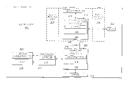
With reference next to Figure 4, an illustration of
an information flow diagram for an electric motor system
is depicted in accordance with an illustrative
embodiment. In this illustrative example, controller 400
is associated with power source 402 and group of electric
motors 404. Controller 400 is an example of controller
21
CA 02865632 2016-05-26
210 in Figure 2. Group of electric motors 404 is an
example of group of electric motors 214 in Figure 2.
Controller 400, power source 402, and group of electric
motors 404 are in communication with each other in this
illustrative example.
As depicted, controller 400 is a flight computer for
an aircraft. Controller 400 is configured to receive
commands 406 and information 408.
In this illustrative example, commands 406 may be
one of autopilot commands, pilot commands, or some other
suitable type of commands. Commands 406 are commands for
group of electric motors 404 in this illustrative
example. For instance, commands 406 may specify
revolutions per minute (RPM) and thrust commands for
operation of one or more of group of electric motors 404.
As illustrated, information 408 is information
provided by various monitoring systems for the aircraft.
Information 408 may take a number of different forms.
For instance, information 408 may take the form of
airspeed, altitude, orientation, or other suitable
information about the aircraft. Information 408 may be
used by controller 400 to control operation of group of
electric motors 404 in this illustrative example.
Power source 402 is in communication with controller
400 in this depicted example. Power source 402 provides
charge state 410 to controller 400 in this illustrative
example. Charge state 410 may be the level of charge
remaining in power source 402. For instance, when power
source 402 is a battery system, charge state 410 may be a
battery charge state which represents the remaining
charge in the battery system.
In this depicted example, controller 400 uses charge
state 410 sent by power source 402 to determine when
power source 402 needs recharging. The determination of
22
CA 02865632 2016-05-26
whether power source 402 needs recharging may be based on
a number of recharging parameters. For instance, when
the charge remaining in power source 402 reaches a
threshold value or the voltage across the battery
terminals becomes lower than a specified value,
controller 400 may switch the state of group of electric
motors 404 from an operating state to a recharge state.
In other words, when charge state 410 reaches a selected
value, group of electric motors 404 may be placed in a
recharge state to recharge power source 402.
Charge state 410 also may include a maximum amount
of regenerative current for power source 402. For
instance, charge state 410 may identify a maximum
allowable value of current to be sent back to power
source 402 by group of electric motors 404. In another
example, power source 402 and controller 400 may identify
the current needed such that power source 402 is
recharged to a state sufficient for completion of its
mission.
Group of electric motors 404 includes four electric
motors in this illustrative example. In particular,
group of electric motors 404 includes electric motor 412,
electric motor 414, electric motor 416, and electric
motor 418 in this illustrative example. Group of
electric motors 404 receives currents from power source
402 when in an operating state and sends currents to
power source 402 when in a recharge state.
In particular, electric motor 412 receives current
420, electric motor 414 receives current 422, electric
motor 416 receives current 424, and electric motor 418
receives current 426 in the operating state. Current
420, current 422, current 424, and current 426 may flow
in the opposite direction during the recharge state. In
some examples, the current flowi'ng in one direction may
23
CA 02865632 2016-05-26
be the same or different than the current flowing in the
opposite direction, depending on the particular
implementation.
In this depicted example, controller 400 sends a
number of motor commands to group of electric motors 404.
For instance, controller 400 sends motor commands 428 to
electric motor 412, motor commands 430 to electric motor
414, motor commands 432 to electric motor 416, and motor
commands 434 to electric motor 418.
In this illustrative example, motor commands 428,
motor commands 430, motor commands 432, and motor
commands 434 may be selected from at least one of
revolutions per minute, thrust, an operating state, a
recharge state, a switching frequency, a regeneration
voltage, a regeneration current, or some other suitable
command. These motor commands may then be implemented by
group of electric motors 404.
Group of electric motors 404 may send feedback to
controller 400 in this illustrative example. In
particular, electric motor 412 sends feedback 436,
electric motor 414 sends feedback 438, electric motor 416
sends feedback 440, and electric motor 418 sends feedback
442. Feedback 436, feedback 438, feedback 440, and
feedback 442 may include at least one of revolutions per
minute, a regeneration current, or some other suitable
type of feedback. Feedback 436, feedback 438, feedback
440, and feedback 442 may be generated by a number of
sensors within each respective motor in this illustrative
example.
In this depicted example, the feedback is processed
by controller 400 and used to adjust future commands sent
to group of electric motors 404. In some cases, the
feedback may be used as a diagnostic tool to identify
problems in one of group of electric motors 404. For
24
CA 02865632 2016-05-26
instance, the feedback may be used to determine if one of
group of electric motors 404 is not working as desired.
Turning next to Figure 5, another illustration of an
information flow diagram for an electric motor system is
depicted in accordance with an illustrative embodiment.
In this depicted example, a more-detailed illustration of
electric motor 412 from Figure 4 is shown.
As depicted, electric motor 412 includes motor
controller 500, voltage controller 502, power inverter
(i.e., an "H" bridge) 504, and motor 506. In this
illustrative example, motor controller 500 is configured
to receive motor commands 428 shown in Figure 4 from
controller 400. Motor controller 500 may be selected
from an impulse width modulation controller, a pulse
width modulation controller, or some other suitable type
of controller.
Motor controller 500 sends commands 510 to voltage
controller 502 and commands 517 to power inverter 504.
Voltage controller 502 may be a device configured to
regulate the voltage applied to electric motor 412 in an
operating state and the voltage applied to the power
supply during a recharge state. For instance, voltage
controller 502 chooses an appropriate voltage to charge
power source 402 when in the recharge state such that
electric motor 412 may charge power source 402 in a
desired manner. Power inverter 504 is controlled to
supply current back to power source 402 at a commanded
magnitude. In other words, voltage controller 502
controls the charging voltage while power inverter 504
controls the magnitude of the current being supplied to
power source 402. Voltage controller 502 may control the
voltage applied to power source 402, regardless of the
commanded voltage, in order to provide a desired charge
setting for power source 402.
CA 02865632 2016-05-26
In this illustrative example, commands 510 and/or
commands 517 may be commands to switch electric motor 412
from an operating state to a recharge state, or from a
recharge state to an operating state. Commands 510 and
commands 517 may be configured such that circuitry within
one or more of voltage controller 502 and power inverter
504 is placed in an on state to allow current to flow in
a desired manner.
Based on commands 517, power inverter 504 may send
or receive current 512. In particular, when electric
motor 412 is in an operating state, power inverter 504
sends current 512 to motor 506. When electric motor 412
is in a recharge state, power inverter 504 receives
current 512 from motor 506. Motor 506 is the mechanical
portion of electric motor 412 in this illustrative
example.
As depicted, voltage controller 502 and power
inverter 504 provide feedback 514 and feedback 516,
respectively, for motor controller 500. For instance,
feedback 514 may include a voltage regenerated for power
source 402 from electric motor 412.
In a similar fashion, motor 506 generates feedback
518 for motor controller 500. Feedback 518 may include
the measured current flowing to and from motor 506,
position information of motor 506, or other suitable
types of feedback. Motor controller 500 then uses this
feedback to generate feedback 436 shown in Figure 4 to
controller 400, further control operation of electric
motor 412 based on motor commands 428 from controller
400, or perform another suitable type of operation.
In this depicted example, while the components of an
electric motor have been described with reference to
electric motor 412, electric motor 414, electric motor
416, and electric motor 418 may include similar
26
CA 02865632 2016-05-26
components to electric motor 412, as described herein.
In other illustrative examples, one or more of group of
electric motors 404 may include different components,
depending on the functionality involved.
With reference next to Figure 6, an illustration of
an information flow diagram for an electric motor in an
operating state is depicted in accordance with an
illustrative embodiment. In this depicted example,
electric motor 412 from Figure 4 is shown in an operating
state. The current flow shown in this figure may be one
example of the current flow during operating state 304 in
Figure 3.
As illustrated, power source 402 provides current
420 to electric motor 412, while controller 400 sends
motor commands 428 to electric motor 412. Current 420
may be supplied at a constant voltage in these
illustrative examples.
In this illustrative example, voltage controller 502
receives current 420. Motor controller 500 receives
motor commands 428. Motor controller 500 then generates
voltage control commands 600 and current control commands
602.
As illustrated, voltage control commands 600 are
configured to control voltage controller 502. Voltage
controller 502 is configured to control the voltage which
is applied across power inverter 504 at the voltage
commanded by voltage control commands 600. Output
voltage 604 is applied across power inverter 504. Based
on output voltage 604 of voltage controller 502 and
current control commands 602 from motor controller 500,
output voltage 606 is applied to motor 508. Output
voltage 606 is applied at the commanded voltage and
commanded current from motor controller 500 in these
illustrative examples.
27
CA 02865632 2016-05-26
In this depicted example, motor 506 coverts this
output voltage 606 to mechanical output 608. This
mechanical power is output shaft power in these
illustrative examples. Mechanical output 608 causes
movement of the aircraft. For example, mechanical output
608 may turn propeller 610. In this manner, electric
motor 412 and additional motors in group of electric
motors 404 may provide movement for the aircraft while in
an operating state.
Turning now to Figure 7, an illustration of an
information flow diagram for an electric motor in a
recharge state is depicted in accordance with an
illustrative embodiment. In this depicted example,
electric motor 412 from Figure 4 is shown in a recharge
state. The current flow shown in this figure may be one
example of the current flow during recharge state 306 in
Figure 3.
As depicted, controller 400 has commanded motor
controller 500 to switch electric motor 412 from an
operating state to a recharge state. In this
illustrative example, mechanical power 700 may be
generated from wind energy spinning propeller 610.
Mechanical power 700 is received by motor 506 and
converted to electrical power.
As illustrated, output voltage 702 is sent to power
inverter 504. Power inverter 504 uses current control
commands 602 to generate output voltage 704 at a desired
level of current. Output voltage 704 is then sent to
voltage controller 502. Based on voltage control
commands 600, voltage controller 502 sends current 420
back to power source 402 at the commanded level of
voltage and current to recharge power source 402.
In this manner, electric motor 412 provides a
desired level of current to recharge power source 402.
28
CA 02865632 2016-05-26
In a similar fashion, electric motor 414, electric motor
416, and electric motor 418 also may provide current to
recharge power source 402.
With reference now to Figure 8, an illustration of a
block diagram of a power source and a current controller
is depicted in accordance with an illustrative
embodiment. Power source 402 takes the form of battery
800 in this illustrative example.
Power source 402 includes battery balancer circuit
802 and commanded current calculator 804 in this
illustrative example. Battery balancer circuit 802 is
configured to balance a charge from different cells
within battery 800 to increase the capacity of battery
800. Battery balancer circuit 802 is also configured to
protect cells within battery 800 from undesirable
overcharging.
In this illustrative example, current from each
motor in group of electric motors 404 in Figure 4 is sent
to battery 800. For instance, a first current 801 is
sent from electric motor 412, a second current 803 is
sent from electric motor 414, a third current 805 is sent
from electric motor 416, and a fourth current 807 is sent
from electric motor 418 in Figure 4. These currents are
used to recharge battery 800 in these illustrative
examples.
As depicted, in response to receiving one or more of
first current 801, second current 803, third current 805,
and fourth current 807, battery charge state 806 is sent
from battery 800 to battery balancer circuit 802.
Battery charge state 806 is a charge state for battery
800 at a current time.
In this illustrative example, battery balancer
circuit 802 uses battery charge state 806 to determine
commanded current 808 and commanded voltage 810.
29
CA 02865632 2016-05-26
Commanded current 808 is a current level for operation of
one or more of group of electric motors 404. This
current is determined by the current needs of battery
800. Commanded voltage 810 is a voltage level for
operation of one or more of group of electric motors 404.
This voltage is determined by voltage needs of battery
800.
As depicted, battery balancer circuit 802 sends
commanded current 808 and commanded voltage 810 to
commanded current calculator 804. Commanded current
calculator 804 is configured to receive number of inputs
812 from group of electric motors 404, commanded current
808, and commanded voltage 810 and use number of inputs
812 to determine a desired level of commanded current for
each of group of electric motors 404.
In this illustrative example, number of inputs 812
may take several different forms. For instances, number
of inputs 812 may take the form of voltage measurements,
current measurements, average duty cycle, a combination
thereof, and other types of information from group of
electric motors 404.
In this depicted example, commanded current
calculator 804 receives average duty cycle 809, average
duty cycle 811, average duty cycle 813, and average duty
cycle 822 from electric motor 412, electric motor 414,
electric motor 416, and electric motor 418, respectively.
Average duty cycle 809, average duty cycle 811, average
duty cycle 813, and average duty cycle 822 may be an
average of the duty cycles measured for electric motor
412, electric motor 414, electric motor 416, and electric
motor 418, respectively, over a selected period of time.
Commanded current calculator 804 also receives
current 814, current 815, current 816, and current 817
from electric motor 412, electric motor 414, electric
CA 02865632 2016-05-26
motor 416, and electric motor 418, respectively. Current
814, current 815, current 816, and current 817 may be the
actual current output of electric motor 412, electric
motor 414, electric motor 416, and electric motor 418,
respectively, in this illustrative example.
From number of inputs 812, commanded current
calculator 804 generates commanded current 818 for
electric motor 412, commanded current 819 for electric
motor 414, commanded current 820 for electric motor 416,
and commanded current 821 for electric motor 418. In
this illustrative example, commanded current calculator
804 is located in controller 400. In some illustrative
examples, commanded current calculator 804 may be located
in a different component within the electric aircraft,
remote to the electric aircraft, or some combination
thereof.
Turning now to Figure 9, an illustration of
equations for calculating a commanded current is depicted
in accordance with an illustrative embodiment. In this
depicted example, equation 900 may be used by commanded
current calculator 804 from Figure 8 to calculate
commanded currents for group of electric motors 404 in
Figure 4.
As depicted, equation 900 is used by commanded
current calculator 804 to determine an effective current,
in/100% DC, for each of group of electric motors 404,
where infb is a measured current for the motor, while DCnfb
is the average duty cycle for the motor. Once effective
current is calculated for all motors in group of electric
motors 404, these effective currents may be input into
equation 902 to determine the total effective current,
i0/ 100% DC.
Next, commanded current, incInd, is determined using
equation 904. In equation 904, i
-cinciftot is the total
31
CA 02865632 2016-05-26
commanded current for group of electric motors 404. The
commanded current for each of group of electric motors
404 is proportional to the measured current of each of
group of electric motors 404. In this manner, commanded
current for group of electric motors 404 may be
determined to operate the electric aircraft in a desired
manner in both the operating state and the recharge
state.
With reference next to Figure 10, an illustration of
a circuit diagram of a voltage controller and a power
inverter for an electric motor is depicted in accordance
with an illustrative embodiment. In this depicted
example, circuit diagrams for voltage controller 502 and
power inverter 504 are shown.
Power inverter 504 is associated with coils 1000
within motor 506 in this illustrative example. Motor
controller 500 is configured to control the current to
coils 1000 to move electric motor 412 in a desired
manner.
In this depicted example, voltage controller 502 is
physically associated with power inverter 504 using
switch 1002, inductor 1004, and diode 1006. Switch 1002
is configured to open and close to direct flow of current
between voltage controller 502 and power inverter 504.
Power inverter 504 then provides current to one or more
of coils 1000 in this illustrative example.
As illustrated, inductor 1004 and diode 1006 are
configured to add capability to voltage controller 502
and power inverter 504 for current to flow in both
directions, depending on the position of switch 1002. In
other words, as the state of electric motor 412 changes,
switch 1002 moves from an open position to a closed
position.
32
CA 02865632 2016-05-26
For instance, when electric motor 412 is in an
operating state, switch 1002 is closed and current flows
to power inverter 504 and coils 1000 to provide
propulsion for electric motor 412. When electric motor
412 is in a recharge state, switch 1002 is open and
current flows through inductor 1004 and diode 1006 to
voltage controller 502 to recharge the power source in
these illustrative examples.
Figures 11-15 illustrate a circuit diagram of a
voltage controller and a power inverter for an electric
motor in accordance with an illustrative embodiment. In
particular, Figures 11-15 show the current flow through
voltage controller 502, power inverter 504, and motor 506
in electric motor 412 during various stages of operation.
Figures 11-13 illustrate a current flow during an
operating state, while Figure 14 and Figure 15 show
current during a recharge state.
Turning to Figure 11, an illustration of a current
flow through a voltage controller is depicted in
accordance with an illustrative embodiment. In this
depicted example, voltage controller 502 includes
switches 1100, while power inverter 504 includes number
of switches 1108. Switches 1100 include switch 1101,
switch 1102, switch 1103, and switch 1105.
As illustrated, switch 1101 and switch 1102 in
switches 1100 have been closed such that current 1104
flows through voltage controller 502. Switch 1002 is
also closed in this depicted example. Current 1104 may
be configured to "charge up" inductor 1106. In other
words, inductor 1106 may temporarily store energy as a
magnetic field. Number of switches 1108 for coils 1000
remain open in this illustrative example.
In Figure 12, an illustration of a current flow
through a voltage controller is depicted in accordance
33
CA 02865632 2016-05-26
with an illustrative embodiment. In this illustrative
example, switch 1102 is closed. Current 1104 flows to
capacitor 1200. Capacitor 1200 is configured to store
energy in an electric field.
As depicted, the charging of capacitor 1200 will
change the voltage across number of switches 1108 to
allow number of switches 1108 to run at a desired
voltage. By controlling a duty cycle of switches 1100 in
voltage controller 502, the voltage across power inverter
504 may be quickly and automatically controlled. In this
illustrative example, controlling the duty cycle of
switches 1100 drives the voltage across power inverter
504 to a desired operational voltage for current control.
Typically, this voltage will be such that the duty cycle
in number of switches 1108 runs with a duty cycle close
to one hundred percent. The higher the percentage of the
duty cycle, the more efficient operation of the system
will be. Accordingly, when number of switches 1108 runs
with a duty cycle close to one hundred percent, the
system is operating at the most efficient mode of
operation.
With reference to Figure 13, an illustration of a
voltage controller and a power inverter is depicted in
accordance with an illustrative embodiment. In this
illustrative example, a charge from capacitor 1200 is
used to drive power inverter 504. In particular, current
1300 is supplied by capacitor 1200.
While capacitor 1200 is supplying current 1300, the
voltage of capacitor 1200 begins to decrease. In
response, motor controller 500 will supply additional
current 1104 to capacitor 1200 to maintain a desired
voltage across power inverter 504. In this depicted
example, current 1300 flows to number of switches 1108
34
CA 02865632 2016-05-26
and coils 1000 to provide propulsion for electric motor
412.
In Figure 14, an illustration of a reverse current
flow through a voltage controller and a power inverter is
depicted in accordance with an illustrative embodiment.
In this depicted example, electric motor 412 is
configured to operate in a recharge state to recharge
power source 402. Accordingly, switch 1002 is open in
this illustrative example, forcing current to flow
through inductor 1004 and diode 1006 to voltage
controller 502.
As illustrated, electromotive force from coils 1000
produces a voltage which drives current 1400 through
number of diodes 1402. Current travels through inductor
1004 and diode 1006 to charge capacitor 1200 in voltage
controller 502. The voltage across capacitor 1200 is
maintained at a charging voltage.
In this stage, current does not flow to power source
402 because switch 1002 is open. As a result, capacitor
1200 continues to be charged until capacitor 1200 reaches
a desired voltage.
Referring next to Figure 15, an illustration of a
voltage controller and a power inverter is depicted in
accordance with an illustrative embodiment. In this
depicted example, switch 1103 in voltage controller 502
is now closed.
As illustrated, capacitor 1200 discharges and
current 1500 flows through voltage controller 502 back to
power source 402. In this manner, voltage controller 502
controls switches 1100 to allow current 1500 to flow back
to power source 402 at a voltage output by capacitor
1200. As a result, power source 402 may be recharged
with a reduced risk of damage to power source 402.
CA 02865632 2016-05-26
The different components shown in Figures 4-15 may
be illustrative examples of how components shown in block
form in Figure 2 and Figure 3 can be implemented.
Additionally, some of the components in Figures 4-15 may
be combined with components in Figure 2 and Figure 3,
used with components in Figure 2 and Figure 3, or a
combination of the two.
For example, although electric aircraft 200 has been
described with reference to a quadcopter, electric
aircraft 200 also may be a helicopter. In this instance,
mechanical motor components may be replaced by electric
motor components as shown in Figures 2-15. As an
example, a helicopter with a fixed pitch tail rotor may
be driven by an electric motor.
In this illustrative example, the removal of
mechanical components, such as a drive shaft or gearbox,
may significantly decrease the weight, cost, and
complexity for manufacturing the helicopter. Moreover,
when mechanical components are replaced by electrical
components, points of failure for mechanical components
may be reduced or eliminated, increasing the reliability
of the motor system.
In this depicted example, an impulse width
modulation controller may be used to control the electric
motor and an energy-harvesting system may be used to
recharge a power source within the helicopter. The use
of an impulse width modulation controller allows the
helicopter to operate at variable speeds.
In still other illustrative examples, more than four
motors may be present in group of electric motors 404
shown in Figure 4. For example, five motors, ten motors,
fifteen motors, or some other suitable number of motors
may be used for a propulsion system and an energy-
harvesting system.
36
CA 02865632 2016-05-26
With reference now to Figure 16, an illustration of
four-quadrant control, is depicted in accordance with an
illustrative embodiment. Controller 210 may be used to
control electric motor 224 of electric aircraft 200 in
Figure 2 to operate in the four quadrants as illustrated
by graph 1600. Controller 210 is configured to control
operation of electric motor 224 in one or more of the
four quadrants illustrated in graph 1600.
As depicted, graph 1600 illustrates torque versus
speed. X-axis 1602 represents speed. Y-axis 1604
represents torque. In this illustrative example, first
quadrant 1606, second quadrant 1608, third quadrant 1610,
and fourth quadrant 1612 are illustrated. First quadrant
1606 represents acceleration of the motor in which speed
is in a first direction with torque in a first direction.
Second quadrant 1608 represents motor braking in which
torque is in the forward direction while speed is in the
reverse direction. Third quadrant 1610 represents
acceleration of the motor with torque in a second
direction and speed in a second direction. Fourth
quadrant 1612 represents braking of the motor running in
reverse. In this quadrant, the speed is in the forward
direction while the torque is in the reverse direction.
The different electric motors in the illustrative
examples may be controlled to operate in one or more of
the four different quadrants described in Figure 16. For
example, controller 210 in Figure 2 may control electric
motor 224 to operate in one or more of first quadrant
1606, second quadrant 1608, third quadrant 1610, and
fourth quadrant 1612.
With reference next to Figure 17, an illustration of
a flowchart of a process for controlling an electric
aircraft is depicted in accordance with an illustrative
embodiment. The process illustrated in Figure 17 may be
37
CA 02865632 2016-05-26
implemented in electric aircraft 200 in Figure 2. In
particular, one or more of the different operations may
be implemented using controller 210 in Figure 2 in
electric aircraft 200.
The process begins by identifying a state for an
electric aircraft (operation 1700). For instance, state
220 for electric aircraft 200 in Figure 2 may be
identified by controller 210. State 220 may be operating
state 304 or recharge state 306 in this illustrative
example.
Next, a group of recharging parameters is identified
for a group of electric motors when the state is a
recharge state present for the electric aircraft
(operation 1702). For instance, group of recharging
parameters 222 is identified for group of electric motors
214 when recharge state 306 is present for group of
electric motors 214. In this depicted example, group of
electric motors 214 is configured to move electric
aircraft 200.
A power source for the electric aircraft is then
recharged using the group of recharging parameters to
control recharging of the power source with the group of
electric motors when the recharge state is present for
the electric aircraft (operation 1704) with the process
terminating thereafter. In this illustrative example,
power source 208 for electric aircraft 200 is recharged
using group of recharging parameters 222 to control
recharging of power source 208 with group of electric
motors 214 when recharge state 306 is present for
electric aircraft 200. For instance, group of recharging
parameters 222 may be used to recharge battery system 209
in one illustrative example.
The flowcharts and block diagrams in the different
depicted embodiments illustrate the architecture,
38
CA 02865632 2016-05-26
functionality, and operation of some possible
implementations of apparatuses and methods in an
illustrative embodiment. In this regard, each block in
the flowcharts or block diagrams may represent a module,
a segment, a function, and or a portion of an operation
or step.
In some alternative implementations of an
illustrative embodiment, the function or functions noted
in the blocks may occur out of the order noted in the
figures. For example, in some cases, two blocks shown in
succession may be executed substantially concurrently, or
the blocks may sometimes be performed in the reverse
order, depending upon the functionality involved. Also,
other blocks may be added in addition to the illustrated
blocks in a flowchart or block diagram.
Turning now to Figure 18, an illustration of a data
processing system in the form of a block diagram is
depicted in accordance with an illustrative embodiment.
Data processing system 1800 may be used to implement one
or more computers in computer system 211 in Figure 2. As
depicted, data processing system 1800 includes
communications framework 1802, which provides
communications between processor unit 1804, storage
devices 1806, communications unit 1808, input/output unit
1810, and display 1812. In some cases, communications
framework 1802 may be implemented as a bus system.
Processor unit 1804 is configured to execute
instructions for software to perform a number of
operations. Processor unit 1804 may comprise a number of
processors, a multi-processor core, and/or some other
type of processor, depending on the implementation. In
some cases, processor unit 1804 may take the form of a
hardware unit, such as a circuit system, an application
39
CA 02865632 2016-05-26
specific integrated circuit (ASIC), a programmable logic
device, or some other suitable type of hardware unit.
Instructions for the operating system, applications,
and/or programs run by processor unit 1804 may be located
in storage devices 1806. Storage devices 1806 may be in
communication with processor unit 1804 through
communications framework 1802. As used herein, a storage
device, also referred to as a computer readable storage
device, is any piece of hardware capable of storing
information on a temporary and/or permanent basis. This
information may include, but is not limited to, data,
program code, and/or other information.
Memory 1814 and persistent storage 1816 are examples
of storage devices 1806. Memory 1814 may take the form
of, for example, a random access memory or some type of
volatile or non-volatile storage device. Persistent
storage 1816 may comprise any number of components or
devices. For example, persistent storage 1816 may
comprise a hard drive, a flash memory, a rewritable
optical disk, a rewritable magnetic tape, or some
combination of the above. The media used by persistent
storage 1816 may or may not be removable.
Communications unit 1808 allows data processing
system 1800 to communicate with other data processing
systems and/or devices. Communications unit 1808 may
provide communications using physical and/or wireless
communications links.
Input/output unit 1810 allows input to be received
from and output to be sent to other devices connected to
data processing system 1800. For example, input/output
unit 1810 may allow user input to be received through a
keyboard, a mouse, and/or some other type of input
device. As another example, input/output unit 1810 may
CA 02865632 2016-05-26
allow output to be sent to a printer connected to data
processing system 1800.
Display 1812 is configured to display information to
a user. Display 1812 may comprise, for example, without
limitation, a monitor, a touch screen, a laser display, a
holographic display, a virtual display device, and/or
some other type of display device.
In this illustrative example, the processes of the
different illustrative embodiments may be performed by
processor unit 1804 using computer-implemented
instructions. These instructions may be referred to as
program code, computer usable program code, or computer
readable program code and may be read and executed by one
or more processors in processor unit 1804.
In these examples, program code 1818 is located in a
functional form on computer readable media 1820, which is
selectively removable, and may be loaded onto or
transferred to data processing system 1800 for execution
by processor unit 1804. Program code 1818 and computer
readable media 1820 together form computer program
product 1822. In this illustrative example, computer
readable media 1820 may be computer readable storage
media 1824 or computer readable signal media 1826.
Computer readable storage media 1824 is a physical
or tangible storage device used to store program code
1818 rather than a medium that propagates or transmits
program code 1818. Computer readable storage media 1824
may be, for example, without limitation, an optical or
magnetic disk or a persistent storage device that is
connected to data processing system 1800.
Alternatively, program code 1818 may be transferred
to data processing system 1800 using computer readable
signal media 1826. Computer readable signal media 1826
may be, for example, a propagated data signal containing
41
CA 02865632 2016-05-26
program code 1818. This data signal may be an
electromagnetic signal, an optical signal, and/or some
other type of signal that can be transmitted over
physical and/or wireless communications links.
The illustration of data processing system 1800 in
Figure 18 is not meant to provide architectural
limitations to the manner in which the illustrative
embodiments may be implemented. The different
illustrative embodiments may be implemented in a data
processing system that includes components in addition to
or in place of those illustrated for data processing
system 1800. Further, components shown in Figure 18 may
be varied from the illustrative examples shown.
Illustrative embodiments of the disclosure may be
described in the context of aircraft manufacturing and
service method 1900 as shown in Figure 19 and aircraft
2000 as shown in Figure 20. Turning first to Figure 19,
an illustration of a block diagram of an aircraft
manufacturing and service method is depicted in
accordance with an illustrative embodiment. During pre-
production, aircraft manufacturing and service method
1900 may include specification and design 1902 of
aircraft 2000 in Figure 20 and material procurement 1904.
During production, component and subassembly
manufacturing 1906 and system integration 1908 of
aircraft 2000 in Figure 20 takes place. Thereafter,
aircraft 2000 in Figure 20 may go through certification
and delivery 1910 in order to be placed in service 1912.
While in service 1912 by a customer, aircraft 2000 in
Figure 20 is scheduled for routine maintenance and
service 1914, which may include modification,
reconfiguration, refurbishment, and other maintenance or
service.
42
CA 02865632 2016-05-26
Each of the processes of aircraft manufacturing and
service method 1900 may be performed or carried out by a
system integrator, a third party, and/or an operator. In
these examples, the operator may be a customer. For the
purposes of this description, a system integrator may
include, without limitation, any number of aircraft
manufacturers and major-system subcontractors; a third
party may include, without limitation, any number of
vendors, subcontractors, and suppliers; and an operator
may be an airline, a leasing company, a military entity,
a service organization, and so on.
With reference now to Figure 20, an illustration of
a block diagram of an aircraft is depicted in which an
illustrative embodiment may be implemented. In this
example, aircraft 2000 is produced by aircraft
manufacturing and service method 1900 in Figure 19 and
may include airframe 2002 with plurality of systems 2004
and interior 2006. Aircraft 2000 may be an electric
aircraft in accordance with an illustrative embodiment.
Examples of systems 2004 include one or more of
propulsion system 2008, electrical system 2010, hydraulic
system 2012, and environmental system 2014. Any number
of other systems may be included. Although an aerospace
example is shown, different illustrative embodiments may
be applied to other industries, such as the automotive
industry. Apparatuses and methods embodied herein may be
employed during at least one of the stages of aircraft
manufacturing and service method 1900 in Figure 19.
In one illustrative example, components or
subassemblies produced in component and subassembly
manufacturing 1906 in Figure 19 may be fabricated or
manufactured in a manner similar to components or
subassemblies produced while aircraft 2000 is in service
1912 in Figure 19. As yet another example, one or more
43
CA 02865632 2016-05-26
apparatus embodiments, method embodiments, or a
combination thereof may be utilized during production
stages, such as component and subassembly manufacturing
1906 and system integration 1908 in Figure 19. One or
more apparatus embodiments, method embodiments, or a
combination thereof may be utilized while aircraft 2000 is
in service 1912 and/or during maintenance and service 1914
in Figure 19. The use of a number of the different
illustrative embodiments may substantially expedite the
assembly of and/or reduce the cost of aircraft 2000.
In particular, electric motor 224 from Figure 2 and
the components within electric motor 224 may be installed
during any one of the stages of aircraft manufacturing
and service method 1900. For example, without
limitation, electric motor 224 and the components within
electric motor 224 may be installed during at least one
of component and subassembly manufacturing 1906, system
integration 1908, routine maintenance and service 1914,
or some other stage of aircraft manufacturing and service
method 1900. Moreover, electric propulsion system 204,
energy-harvesting system 206, and controller 210 may be
used during in-service 1912 to control aircraft 2000 in a
desired manner.
Thus, the illustrative embodiments provide a method
and apparatus for recharging a battery system. In one
illustrative example, an apparatus comprises a
controller. The controller is configured to identify a
state for an aircraft and identify a group of recharging
parameters for a number of electric motors. The number
of electric motors is configured to move the aircraft
through the air when a recharge state is present for the
aircraft. The controller is further configured to
recharge a battery system for the aircraft using the
group of parameters and control recharging of the battery
44
CA 02865632 2016-05-26
system with the group of electric motors when the
recharge state is present for the aircraft.
The illustrative embodiments enable recharge
capabilities for an electric aircraft while the electric
aircraft is in the field. Rather than returning to base,
an electric aircraft may find a place to rest and use its
propulsion system as an energy-harvesting system to
generate energy from wind power. In this manner, power
supplies for electric aircraft may be recharged and
missions may be continued longer than with currently used
electric aircraft. Moreover, with the use of a voltage
controller and power inverter, power may be supplied back
to the power source, such as a battery system, at a
desired voltage and current level such that the power
source is less likely to be damaged during recharging.
The circuit architecture for an illustrative
embodiment allows a desired level of current to flow in
two directions, without a substantial increase in weight,
complexity, cost, or a combination thereof for
manufacturing the electric aircraft. Additionally, a
controller configured to communicate with the power
source and the group of electric motors receives constant
feedback to aid in determining current commands for
continued operation of one or more electric motors. As a
result, four-quadrant control of the electric motors may
be realized to propel and recharge an electric aircraft.
The description of the different illustrative
embodiments has been presented for purposes of
illustration and description, and is not intended to be
exhaustive or limited to the embodiments in the form
disclosed. Many modifications and variations will be
apparent to those of ordinary skill in the art. Further,
different illustrative embodiments may provide different
features as compared to other illustrative embodiments.
CA 02865632 2016-05-26
The embodiment or embodiments selected are chosen and
described in order to best explain the principles of the
embodiments, the practical application, and to enable
others of ordinary skill in the art to understand the
disclosure for various embodiments with various
modifications as are suited to the particular use
contemplated.
46