Note: Descriptions are shown in the official language in which they were submitted.
CA 02865649 2016-08-31
55372-3
COLLISIONAL BROADENING COMPENSATION USING REAL OR
NEAR-REAL TIME VALIDATION IN SPECTROSCOPIC ANALYZERS
CROSS-REFERENCE TO RELATED APPLICATIONS
10011 This application claims priority to U.S. Patent Application
No. 13/428,591
filed on March 23, 2012, which is related to U.S. Patent
Application No. 13/026,921 and U.S. Patent Application No.
13/027,000 and U.S. Patent No. 7,508,521, and U.S. Patent No.7,704,301,
and U.S. Patent No. 7,819,946.
TECHNICAL FIELD
[002] The subject matter described herein relates to compensation
for the effects of
collisional broadening on measurements, for example for detection and/or
quantification of
trace gases, made by spectroscopic analyzers.
BACKGROUND
10031 Spectroscopic analysis generally relies on detection and
quantification of
emission or absorption of radiation by matter (e.g. individual molecules in
analysis of gas
phase compounds). The radiation is absorbed or emitted with a particular
energy determined
by transitions occurring to the molecules of an analyte. For example, in
infrared
spectroscopy, discrete energy quanta are absorbed by molecules due to
excitation of
vibrational or rotational transitions of the intra-molecular bonds. The
collision of other
molecules in a gas mixture with the emitting or absorbing molecules and the
collision
between the emitting or absorbing molecules themselves can perturb the energy
levels of the
emitting or absorbing molecules and therefore cause broadening of the emission
or absorption
1
CA 02865649 2014-08-26
WO 2013/142737
PCT/US2013/033383
line shape. Broadening of spectral line shapes can depend on any or all of the
pressure, the
temperature, and composition of the gas mixture in addition to the spectral
transition and
concentration of a particular target analyte. Quantitative measurement errors
can occur if the
spectroscopic analyzer is used to measure a target analyte in a sample gas
with combination
of pressure, temperature and composition of background gas that differs from
the gas mixture
used to calibrate the analyzer. These errors have been found to be a
substantial challenge for
optical measurement of important trace level impurities (e.g. less than
approximately 10,000
ppm) in natural gas quality control, petrochemical production, quality control
and
environmental emissions control, and the like, but are not limited to those
applications. The
important impurities can include but are not limited to water (H20), hydrogen
sulfide (H2S),
other sulfur compounds, other acids, carbon dioxide (CO2), carbon monoxide
(CO), ammonia
(NH3), acetylene (C2H2), other hydrocarbons, other hydro-fluoro-chloro-
carbons, and
combinations thereof.
[004] One or
more approaches can be applied to compensate for broadening caused
by differences in pressure and temperature during quantitative target analyte
analysis. For
example, the pressure and/or temperature of the sample gas can be maintained
sufficiently
close to the calibration gas pressure and/or temperature by proper sample
conditioning,
including pressure regulation and temperature stabilization of the sample gas.
In another
example, real time measurement of pressure and temperature can be used to
compensate for
the collisional broadening change by applying theoretical models, including
but not limited to
polynomial corrections, pressure temperature matrixes, chemometrics,
experimental
calibrations, and the like. In another example parameters of the spectroscopic
measurement
(e.g. the harmonic modulation parameters) can also be adjusted in real time to
compensate for
line shape broadening due to changes in sample gas pressure. An example of
such an
2
CA 02865649 2016-08-31
55372-3
approach is described in co-owned U.S. Patent No. 7,508,521.
[005] Direct absorption spectroscopy approaches can be used for measurement
of
target analyte concentrations exceeding approximately 10,000 ppm and
background gas
mixes which offer little or substantially no interfering absorption at the
wavelength of the
target analyte spectral line. Integration over the some or all of the line
shape of the target
analyte spectrum can provide a quantitative target analyte concentration,
which is
proportional to the area of the spectral line shape but does not depend upon
the line shape
itself.
[006] However, there are currently no available approaches that provide
experimental or theoretical compensation of spectral line shape changes caused
by collision
of the target analyte with molecules in a gas sample having different mass and
structure and
as a result of changing composition of the gas sample. Compensating for
spectral line shape
changes caused by changing background sample gas composition is critically
important,
especially for all harmonic spectroscopy approaches, which typically have to
be used to
measure target analyte concentrations below approximately 10,000 ppm and from
ppb levels
(e.g. approximately 1 to 5 ppb) to parts per hundred (e.g. approximately 1% to
10% or even
to 75% or higher) in sample gases which include absorption by one or more
compounds
present at non-negligible concentrations in the background and in applications
in which
spectrally broadly absorbing gases are present or in which accumulation of
condensates on
optical surface sin the absorbing beam path is expected to occur. As an
example, pipeline
corrosion protection and natural gas tariff control in the United States
typically require
measurement of water vapor (H20) in natural gas streams within an uncertainty
limit of 4
ppm, over a range of approximately 0 ppm to 400 ppm or higher. The composition
of a
typical natural gas stream can change over a very wide range, with methane
(C111) tending to
3
CA 02865649 2016-08-31
55372-3
vary within a mole fraction range of approximately 50% to 100%; carbon dioxide
(CO2)
tending to vary within a mole fraction range of approximately 0% to 15%; and
ethane (C2H0,
propane (C3H8), and butane (C4H10) combined tending to vary in accordance with
actual
methane and carbon dioxide concentrations to make up 100% of the natural gas
stream.
[007] Typical industry standard moisture analyzers based on tunable diode
laser
spectrometers, for example a SpectraSensors model SS2000 (available from
SpectraSensors,
Inc. of Houston, Texas) or a General Electric Aurora (available from GE
Measurement &
Control Solutions of Billerica, Massachussetts) may not be capable of
providing necessary
measurement accuracy over such a wide range of stream component variation due
to the
spectral line shape broadening caused by unknown gas sample composition. In
another
example, the U.S. Department of Energy (DOE) sponsored an evaluation project
entitled
"Development of In Situ Analysis for the Chemical Industry" that was conducted
by the
DOW Chemical Company and that concluded that harmonic spectroscopy tunable
diode
lasers are not well suited for gas analysis applications in the chemical
industry due to their
measurement sensitivity to gas composition changes. The report detailing the
results of this
study is "In-Situ Sensors for the Chemical Industry¨Final Report," the Dow
Chemical
Company, Principle investigator: Dr. J.D. Tate, project No. DE-FC36-o21D14428,
pp. 1-37,
Jun. 30, 2006.
SUMMARY
[008] In one aspect of the currently disclosed subject matter, a method
includes
receiving or collecting validation verification data quantifying an intensity
of light reaching a
detector of a spectrometer from a light source of the spectrometer after the
light passes
through a validation gas across a known path length. The validation gas
includes a known
amount of an analyte compound and an undisturbed background composition that
is
4
CA 02865649 2014-08-26
WO 2013/142737
PCT/US2013/033383
representative of a sample gas background composition of a sample gas to be
analyzed using
a spectrometer. The sample gas background composition includes one or more
background
components other than the analyte compound. The validation verification data
are compared
with stored calibration data for the spectrometer to calculate a concentration
adjustment
factor, and the concentration adjustment factor is used to modify sample
measurement data
collected with the spectrometer to compensate for collisional broadening of a
spectral peak of
the analyte compound by the background components in the sample gas.
[009] In interrelated aspects of the current subject matter, an apparatus
can include a
tangibly embodied machine-readable medium operable to or otherwise storing
instructions
that cause one or more machines (e.g., computers, programmable processors,
etc.) to perform
operations as described herein. Similarly, computer systems are also described
that may
include at least one processor and a memory coupled to the at least one
processor. The
memory may include one or more programs that cause the at least one processor
to perform
one or more of the operations described herein.
[0010] In optional variations, one or more of the following features can
be included in
a method or apparatus in any feasible combination. A method can optionally
include
generating the validation gas, and an apparatus can include a validation gas
generation
system. The generating of the validation gas (for example by a validation gas
generation
system) can optionally include treating a volume of the sample gas to remove
or otherwise
substantially reduce a concentration of the analyte compound, and adding a
known mass of
the analyte compound to the treated sample gas volume. The treating of the
volume of the
sample gas can optionally include directing the volume of the sample gas
through a gas
processor, which can optionally include at least one of a scrubber, a
purifier, a chemical
converter, a chemical separator, a distillation columnõ a separation column, a
dryer, and the
like. The known mass of the analyte compound can optionally be added (for
example by a
CA 02865649 2014-08-26
WO 2013/142737
PCT/US2013/033383
validation gas generation system) by a process comprising one or more of
adding a measured
volume of the analyte compound as a gas, liquid, or solid to the volume of the
treated sample
gas; flowing the volume of the treated sample gas as a treated sample gas
stream past an
analyte compound source that emits the analyte compound into the treated
sample gas stream
at a known and controlled mass and/or volume flow rate; and adding, at a known
flow rate, a
gas mixture containing the analyte compound at a known concentration to the
treated sample
gas stream.
100111 The calculation of the concentration adjustment factor can
optionally include
determining one or more of a difference, a ratio, a mean square error (mse), a
coefficient of
determination (R2), a cross correlation function, a cross correlation
integral, and a regression
coefficient in one or more of a light intensity domain and a wavelength domain
for one or
more parts or an entirety of the validation verification data and the
calibration data. The
determining can optionally include using one or more mathematical methods of
subtracting,
dividing, cross correlation, convolution, curve fitting, regression, and
optimization. The
calculation of the concentration adjustment factor can optionally include
application of a
chemometrics-based method.
[0012] In further optional variations, an apparatus can optionally include
a light
source, which can include, but is not limited to one or more of a tunable
diode laser, a tunable
semiconductor laser, a quantum cascade laser, a vertical cavity surface
emitting laser
(VCSEL), a horizontal cavity surface emitting laser (HCSEL), a distributed
feedback laser, a
light emitting diode (LED), a super-luminescent diode, an amplified
spontaneous emission
(ASE) source, a gas discharge laser, a liquid laser, a solid state laser, a
fiber laser, a color
center laser, an incandescent lamp, a discharge lamp, and a thermal emitter.
An apparatus
can also optionally include a detector, which can include, but is not limited
to one or more of
an indium gallium arsenide (InGaAs) detector, an indium arsenide (InAs)
detector, an indium
6
CA 02865649 2016-08-31
55372-3
phosphide (InP) detector, a silicon (Si) detector, a silicon germanium (SiGe)
detector, a
germanium (Ge) detector, a mercury cadmium telluride detector (HgCdTe or MCT),
a lead
sulfide (PbS) detector, a lead selenide (PbSe) detector, a thermopile
detector, a multi-element
array detector, a single element detector, and a photo-multiplier.
100131 Implementations of the current subject matter can provide one or more
advantages. For
example, the flow configuration used in validating a spectroscopic measurement
can impact
the accuracy and repeatability of the validation and thus its applicability to
collisional
broadening compensation. Approaches consistent with the current subject matter
enable the
use of a validation stream whose composition, with the exception of the
concentration of the
one or more analyte compounds, closely mimics that of the sample gas in which
the one or
more analyte compounds are detected and/or quantified. Application of a
concentration
adjustment factor as described herein can establish calibration fidelity of a
spectroscopic
analyzer, even with a changing background composition of the gas being
sampled. This
capability can constitute a significant advance, for example with harmonic
spectroscopy,
which suffers from collisional broadening causing reading offsets that are
generally difficult
or even impossible to accurately model.
[0013a] According to another aspect, there is provided a method for
compensation of
collisional broadening on measurement results of a spectroscopic analyzer,
comprising the
steps: receiving validation verification data quantifying an intensity of
light reaching a
detector of a spectrometer from a light source of the spectrometer after the
light passes
through a validation gas across a known path length, the validation gas
comprising a known
amount of an analyte compound and an undisturbed background composition that
is
representative of a sample gas background composition of a sample gas to be
analyzed using
the spectrometer, the sample gas background composition comprising one or more
background components other than the analyte compound; comparing the
validation
verification data with stored calibration data for the spectrometer;
calculation of a
concentration adjustment factor based on the comparison, to account for
differences between
a first background condition of the validation gas, and a second background
condition of a
calibration gas used to prepare a stored reference spectrum; and modifying,
using the
7
CA 02865649 2016-08-31
55372-3
concentration adjustment factor, sample measurement data collected with the
spectrometer to
compensate for collisional broadening of a spectral peak of the analyte
compound by the
background components in the sample gas.
[001313] According to another aspect, there is provided an apparatus for
compensation of
collisional broadening on measurement results of a spectroscopic analyzer,
comprising: a
spectrometer with a light source and a detector, a machine readable medium
storing
instructions that, when executed by at least one programmable processor, cause
the at least
one programmable processor to perform operations comprising: receiving
validation
verification data quantifying an intensity of light reaching the detector of
the spectrometer
from the light source of the spectrometer after the light passes through a
validation gas across
a known path length, the validation gas comprising a known amount of an
analyte compound
and an undisturbed background composition that is representative of a sample
gas background
composition of a sample gas to be analyzed using a spectrometer, the sample
gas background
composition comprising one or more background components other than the
analyte
compound; comparing the validation verification data with stored calibration
data for the
spectrometer; calculation of a concentration adjustment factor based on the
comparison, to
account for differences between a first background condition of the validation
gas, and a
second background condition of a calibration gas used to prepare a stored
reference spectrum;
and modifying, using the concentration adjustment factor, sample measurement
data collected
with the spectrometer to compensate for collisional broadening of a spectral
peak of the
analyte compound by the background components in the sample gas.
[0013c] According to another aspect, there is provided a system for
compensation of
collisional broadening on measurement results of a spectroscopic analyzer,
comprising: a
spectrometer with a light source to emit light; and a detector positioned a
known path length
from the light source to detect the light emitted from the light source;
wherein: receiving
validation verification data quantifying an intensity of the light reaching
the detector from the
light source, after the light passes through a validation gas across the known
path length, the
validation gas comprising a known amount of an analyte compound and an
undisturbed
background composition that is representative of a sample gas background
composition of a
7a
CA 02865649 2016-08-31
55372-3
sample gas to be analyzed using a spectrometer, the sample gas background
composition
comprising one or more background components other than the analyte compound;
the
validation verification data is compared with stored calibration data for the
spectrometer;
calculation of a concentration adjustment factor based on the comparison, to
account for
differences between a first background condition of the validation gas, and a
second
background condition of a calibration gas used to prepare a stored reference
spectrum; and a
sample measurement data collected with the spectrometer is modified, using the
concentration
adjustment factor, to compensate for collisional broadening of a spectral peak
of the analyte
compound by the background components in the sample gas.
[0014] The details of one or more variations of the subject matter described
herein are set
forth in the accompanying drawings and the description below. Other features
and advantages
of the subject matter described herein will be apparent from the description
and drawings, and
from the claims. It should be noted that the current subject matter
contemplates both a flowing
sample gas stream and a static sample gas from which a sample gas volume can
be withdrawn.
The term "sample gas volume" or "gas volume" as used herein therefore refers
to either a
flowing volume or a static, batch volume of gas.
7b
CA 02865649 2014-08-26
WO 2013/142737
PCT/US2013/033383
DESCRIPTION OF DRAWINGS
[0015] The accompanying drawings, which are incorporated in and constitute
a part
of this specification, show certain aspects of the subject matter disclosed
herein and, together
with the description, help explain some of the principles associated with the
disclosed
implementations. In the drawings,
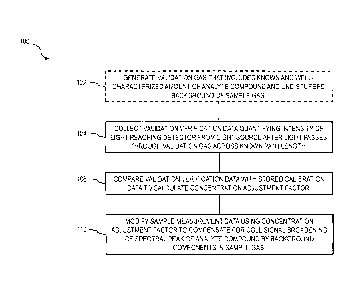
[0016] FIG. 1 is a process flow diagram illustrating aspects of a method
having one or
more features consistent with implementations of the current subject matter;
[0017] FIG. 2 is a diagram illustrating aspects of a system showing
features consistent
with implementations of the current subject matter;
[0018] FIG. 3 is a diagram illustrating aspects of another system showing
features
consistent with implementations of the current subject matter; and
[0019] FIG. 4 is a diagram illustrating aspects of yet another system
showing features
consistent with implementations of the current subject matter.
[0020] When practical, similar reference numbers denote similar
structures, features,
or elements.
DETAILED DESCRIPTION
[0021] To address the aforementioned and other potential issues with
analytical
validation of spectroscopic measurements, implementations of the current
subject matter can
provide a trace gas generator that adds a known and temporally consistent and
stable amount
of a trace analyte to a gas stream to facilitate the use of that gas stream as
a validation stream
for use in validation of a spectrometer and compensation for collisional
broadening effects
that can impact the analysis. Approaches consistent with implementations of
the current
subject matter can be advantageous for in-the-field preparation of a standard
validation gas
8
CA 02865649 2014-08-26
WO 2013/142737
PCT/US2013/033383
for use in conjunction with systems that detect and/or quantify a
concentration of one or more
trace analytes in a gas mixture that includes a complex and/or varying
background of other
compounds whose spectral absorbance characteristics may or may not overlap
with those of
the trace analyte(s). Such approaches can also be advantageous for measurement
of one or
more trace analytes in a toxic, environmentally incompatible, or corrosive
background, such
as for example vinyl-chloride monomers (VCM), chlorine (C12), ammonia (NH3),
hydrogen
chloride (HCI), hydrogen fluoride (HF), hydrogen sulfide (H25), hydrogen
arsenide (AsH3),
hydrogen phosphide (PH3), hydrogen cyanide (HCN), and the like, for which
previously
available approaches may have required substitution of a non-toxic gas, such
as for example
nitrogen (N2), for the calibration of the optical trace gas analyzer.
Approaches consistent
with implementations of the current subject matter can also be advantageous
for measurement
of one or more trace analytes in a gas mixture containing toxic,
environmentally
incompatible, or corrosive compounds that have to be eliminated or substituted
during the
calibration.
[0022] Gas
sampled from a gas source can include one or more analyte compounds.
Detection and/or quantification of the concentration of such analyte compounds
can be
performed by spectroscopic analysis. To compensate for the effects of
collisional broadening
on the results of the spectroscopic analysis, the current subject matter makes
use of a
validation stream that resembles the sample gas as closely as is possible. The
validation
stream can be prepared by first selectively removing or at least substantially
reducing the
concentration of the analyte or analytes in the sample gas from the gas source
and then
adding the analyte or analytes to the neat (free of the analyte or analytes)
sample gas at a well
controlled and accurately known mass and/or volume (note: perm tube vs.
premixed bottle)
delivery rate to produce a consistent, controlled, and well known
concentration of the analyte
or analytes in the validation stream. A test spectrum collected using this
validation stream
9
CA 02865649 2014-08-26
WO 2013/142737
PCT/US2013/033383
can be compared to a previously stored reference spectrum collected using the
same
analytical system during a calibration process. Based on this comparison, a
concentration
adjustment factor can be determined to account for differences between a first
background
condition, including for example chemical composition, pressure and
temperature, etc., of the
validation stream and a second background condition of a calibration gas used
to prepare the
stored reference spectrum. Alternatively, a test spectrum collected using the
sample stream
can be compared to the test spectrum collected using the validation stream
instead of the
previously stored reference spectrum to directly generate a more accurate
concentration
reading.
[0023] Analyte
compounds with which implementations of the current subject matter
can be used include, but are not limited to, hydrogen sulfide (H2S); hydrogen
chloride (HC1);
water vapor (H20); hydrogen fluoride (HF); hydrogen cyanide (HCN); hydrogen
bromide
(HBr); ammonia (NH3); arsine (AsH3); phosphine (PH3); oxygen (02); carbon
monoxide
(CO); carbon dioxide (CO2); hydrocarbons, including but not limited to methane
(CH4),
ethane (C2H6), ethene (C2H4), acetylene (C2H2), etc.; and the like.
[0024] The
flow chart 100 of FIG. 1 illustrates features of a method consistent with at
least some implementations of the current subject matter. At 102, a validation
gas is
generated to contain one or more analyte compounds in an amount or
concentration that is
known or at least well-characterized. As used herein, the term "known" is
intended to refer to
a concentration, amount, or the like that is known to the extent possible in
light of inherent
errors in measurement of an amount or concentration of a validation gas. In
some situations,
it is acknowledged and one of ordinary skill in the art would readily
understand that it may
not be feasible to "know" the amount or concentration of the one or more
analytes in a
validation gas to a complete certainty. In such cases, such an amount or
concentration can in
some examples be considered to be "well-characterized" if measured to the
accuracy of an
CA 02865649 2014-08-26
WO 2013/142737
PCT/US2013/033383
available instrument or instruments or otherwise produced in a reasonably well-
controlled
and reasonably reproducible manner. When the term "known" is used herein in
reference to a
concentration of an analyte, it should be readily understood that the
foregoing explanation
applies and that descriptions herein of known concentrations or amounts are
assumed to refer
to such values that are known and/or well-characterized within a reasonable
margin of error.
[0025] In an implementation, a validation gas can be generated by first
treating a
volume of a sample gas to remove or otherwise substantially reduce a
concentration of an
analyte compound in the sample gas, for example by directing the sample gas
through a gas
processor, which can optionally include but is not limited to a scrubber, a
purifier, a dryer, a
chemical treatment or conversion process, or the like. To generate the known
concentration
of the analyte compound in the treated sample gas volume, after treating the
sample gas
volume by the gas processor, an analyte compound can added to the treated
sample gas
stream at a known (or at least well-characterized) and controlled mass and/or
volume flow
rate. A known mass of the analyte compound can be added using one or more
processes,
including but not limited to adding a measured volume of the analyte compound
as a gas,
liquid, or solid to the volume of the treated sample gas; flowing the volume
of the treated
sample gas as a treated sample gas stream past an analyte compound source that
emits the
analyte compound into the treated sample gas stream at a known and controlled
mass and/or
volume flow rate; and adding, at a known flow rate, a gas mixture containing
the analyte
compound at a known concentration to the treated sample gas stream.
[0026] At 104, validation verification data, for example a test spectrum,
are received
or collected for the validation gas, for example at a programmable processor
that can be local
to the spectrometer or remotely connected via a wired or wireless network or
other
communication link. The receiving of the validation verification data can
occur
synchronously with its generation by the spectrometer or asynchronously (e.g.
with a time
11
CA 02865649 2014-08-26
WO 2013/142737
PCT/US2013/033383
delay for transmission or in discrete packets of data). The validation
verification data
quantify a first intensity of light reaching a detector from a light source
after the light passes
through the validation stream across a first known path length. The validation
verification
data are compared at 106 with stored calibration data, for example a
previously stored
reference spectrum collected with the same analyzer system using a reference
gas of a known
concentration, to calculate a concentration adjustment factor. At 110, the
concentration
adjustment factor is used to modify sample measurement data quantifying a
second intensity
of light reaching the detector from the light source after the light passes
through a sample
stream or volume of sample gas across a second known path length that can
include all or
part of the first known path length. The modifying of the sample measurement
data can
provide a compensation for collisional broadening of spectral peaks of the one
or more
analyte compounds in the sample gas. This compensation can be used to provide
a more
accurate measurement and/or to validate a measurement of a spectral analyzer
relative to a
previous calibration state.
[0027] The
concentration adjustment factor can be calculated as one or more of the
difference, the ratio, the mean square error (mse), the coefficient of
determination (R2), the
cross correlation function or integral, the regression coefficients in one or
more of the light
intensity domain and the wavelength domain, and the like for one or more parts
or the
entirety of the validation verification data and the calibration data using
one or more
mathematical methods of subtracting, dividing, cross correlation, convolution,
curve fitting,
regression, optimization, and the like. The concentration adjustment factor
can be used to
modify the sample measurement data before or after comparing the sample
measurement data
with the calibration data. The modification of the sample measurement data
using the
concentration adjustment factor can utilize one or more mathematic methods of
subtracting,
dividing, cross correlation, convolution, curve fitting, regression and
optimization.
12
CA 02865649 2014-08-26
WO 2013/142737
PCT/US2013/033383
Alternatively, the sample measurement data can be compared to the validation
verification
data instead of the calibration data to directly generate the more accurate
concentration
reading. The comparison of the sample measurement data and the validation
verification data
can utilize one or more mathematical methods of subtracting, dividing, cross
correlation,
convolution, curve fitting, regression, optimization, and the like to generate
the ratio between
the sample measurement data and the validation verification data.
[0028] FIG. 2 shows an example of a system 200 having features consistent
with one
or more implementations of the current subject matter. A light source 202
provides a
continuous or pulsed light that is directed to a detector 204 via a path
length 206. The path
length 206 can traverse one or more gas volumes. In the example system 200
shown in FIG.
2, the path length 206 twice traverses each of a first volume 212 and a second
volume 214,
which are contained within a single optical cell 216 that includes a first
window or other at
least partially radiation transmissive surface 220, a second window or other
radiation
transmissive surface 222, and a mirror or other at least partially radiation
reflective surface
224 that at least partially define the first volume 212 and the second volume
214. Sample gas
can, in some implementations, be obtained from a gas source, which in the
example of FIG. 2
is a pipeline 226, for delivery to the first volume 212 and the second volume,
for example via
a sample extraction port or valve 230 that receives the sample gas from the
source and a first
inlet port 232 delivering gas to the first volume 212 and a second inlet port
234 delivering gas
to the second volume 214. Gas in the first volume 212 can exit the first
volume 212 via a
first outlet valve or port 236 and gas in the second volume 214 can exit the
second volume
212 via a second outlet valve or port 240
100291 Gas passing to the first volume 212 can be directed first through a
gas
processor 242 that removes or at least reduces a concentration of the analyte
compound in the
gas flowing to the first volume 212 as a first process in creating a
validation stream. The gas
13
CA 02865649 2016-08-31
. 55372-3
processor 242 can advantageously not substantially affect the concentration of
at least one
background compound in the validation stream. The gas processor 242 can
optionally be a
scrubber, a purifier, a dryer, a chemical conversion unit, or the like that
reduces a
concentration of the analyte compound in the validation stream, advantageously
to an at least
approximately negligible level, for example by chemically or physically
removing the analyte
compound from the gas phase to another phase (e.g. solid, adsorbed, absorbed,
liquid,
dissolved, etc.) or by chemically converting the analyte compound to another
chemical
species whose spectral characteristics differ sufficiently from those of the
analyte compound
so as to not interfere with measurements at a narrow line width spectral
region focused on an
absorption or emission characteristic of the analyte compound.
[0030] The validation stream can pass from the gas processor 242
to an analyte
generator 244 that adds the analyte compound to the validation stream. In some
variations,
the analyte generator 244 can be one or more diffusion-type gas generators,
such as for
example one or more osmotic membrane generators or permeation tubes (an
illustrative
example of which is the G-Cal product line available from 'VICI Metronics of
Poulsbo, WA).
Alternatively, the analyte generator 244 can be a mixer that blends premixed
analyte in one or
more carrier gases from a compressed gas cylinder 248 with the neat sample
stream flowing
out of the gas processor 242.
[0031] The first volume 212 and the second volume 214 can in some
implementations
be configured as a sample measurement cell and a validation cell such as those
illustrated and
described in co-pending and co-owned application for U.S. Patent No.
13/026,921 and
13/027,000. Other configurations are within the scope of the current subject
matter.
For example, either or both of the first volume 212 and the second volume 214
can be free gas space,
for example part or all of the exhaust stack of a combustion installation,
chemical
processing plant, etc.
14
CA 02865649 2014-08-26
WO 2013/142737
PCT/US2013/033383
[0032] As
shown in FIG. 2, each of the first volume 212 and the second volume 214
can be configured as separate optical cells, one for containing a volume of
the validation
stream, and the other for containing either an untreated volume of the sample
gas or a "zero
gas" having at least one of known and negligible first light absorbance
characteristics that
overlap second light absorbance characteristics of the analyte compound within
a wavelength
range of the light provided by the light source 202. The zero gas can in some
implementations be a gas provided from a compressed gas cylinder 246 connected
to a supply
line to the second inlet port 234 via a connector port or valve 250. The zero
gas can
optionally include one or more of a noble gas, nitrogen gas, oxygen gas, air,
hydrogen gas, a
homo-nuclear diatomic gas, at least a partial vacuum, a hydrocarbon gas, a
fluoro-carbon gas,
a hydro-fluoro-carbon gas, a chloro-carbon gas, a chloro-fluoro-carbon gas, a
hydro-chloro-
carbon gas, a hydro-fluoro-chloro-carbon gas, carbon monoxide gas, carbon
dioxide gas,
some other gas including known concentrations of one or more compounds with
known, or
optionally at least well characterized, spectroscopic responses at one or more
wavelengths
provided by the light source 202, or the like. The zero gas can optionally be
passed through a
scrubber or chemical converter to remove or reduce a concentration of the
trace analyte
therein before directing the zero gas into the path of the light.
[0033] A
controller 252, which can include one or more programmable processors or
the like, can communicate with one or more of the light source 202 and the
detector 204 for
controlling the emission of the light 206 and receiving signals generated by
the detector 204
that are representative of the intensity of light impinging on the detector
204 as a function of
wavelength. In various implementations, the controller 252 can be a single
unit that performs
both of controlling the light source 202 and receiving signals from the
detector 204, or it can
be more than one unit across which these functions are divided. Communications
between
CA 02865649 2014-08-26
WO 2013/142737
PCT/US2013/033383
the controller 252 or controllers and the light source 202 and detector 204
can be over wired
communications links, wireless communications links, or any combination
thereof.
[0034] One or
both of the first volume 212 and the second volume 214 can be
maintained at a stable temperature and pressure. Alternatively, one or both of
the first
volume 212 and the second volume 214 can include one or more temperature
and/or pressure
sensors to determine a current temperature and pressure within that volume for
use in one or
more calculations to compensate for temperature and/or pressure changes
relative to a
validation or calibration condition of the spectroscopic instrument.
[0035] The
system 200 can be operated to perform a collisional broadening
compensation measurement as discussed above by running the validation gas
through the first
volume 212 and the zero gas through the second volume 214. To perform a
measurement of
the analyte concentration in the gas from the gas source, the sample gas can
be directed into
the second volume 214. During this process, the validation gas can continue to
be provided
to the first volume 212. The light intensity arriving at the detector 204 from
the light source
202 after traversing the path length can be corrected mathematically to
account for absorption
by the analyte compound present in the validation gas in the first volume 212.
[0036] In
another implementation, which is illustrated in FIG. 3, a system includes a
single volume 302 within an optical cell 216. One or more flow switching
valves or
comparable devices 304 can be included on a sample gas supply line from a gas
source,
which can be a pipeline 226 as shown in FIG. 3, some other source of sample
gas, or the like.
The flow switching valves or comparable devices 304 can be switched to direct
gas from the
gas source to flow through a gas processor 242 and an analyte generator 244 to
generate a
validation gas as discussed above. The validation gas is delivered to the
single volume 302
via the inlet port or valve 234. The system 300 can be operated to perform a
collisional
broadening compensation measurement as discussed above by running this
validation gas
16
CA 02865649 2014-08-26
WO 2013/142737
PCT/US2013/033383
through the single volume 302. To perform a measurement of the analyte
concentration in
the gas from the gas source, the flow switching valves or comparable devices
304 can be
switched to direct gas to the single volume 302 via the inlet port or valve
234 without passing
through the gas processor 242 and the analyte generator 244.
[0037] The
controller 252, or alternatively one or more other processors that are
either collocated with the other components or in wireless, wired, etc.
communication
therewith, can perform the processing functions discussed above in reference
to the method
illustrated in FIG. 1.
[0038] In yet
another implementation, which is illustrated in FIG. 4, a system 400
includes a first volume 402 and a second volume 404 included within two
separate optical
cells 406 and 410, respectively. The initial laser beam or series of laser
pulses 412 from the
laser source 202 can be split into a first split beam 414 and a second split
beam 416 via a
beam splitting, demultiplexing, etc. device 420, which can include free space
or fiber based
beam splitters, gratings, fiber splitters, or other partial radiation
transmissive and/or anti-
reflective or reflective surfaces, which can include, but are not limited to
oxides, such as for
example silicon dioxide (Si02), titanium dioxide (Ti02), aluminum oxide
(A1203), hafnium
oxide (Hf02), zirconium oxide (Zr02), scandium oxide (Sc203), niobium oxide
(Nb02), and
tantalum oxide (Ta205); fluorides, such as for example magnesium fluoride
(MgF2),
lanthanum fluoride (LaF3), and aluminum fluoride (AIF3); etc.; and/or
combinations thereof;
metallic materials including but not limited to gold (Au), silver (Ag), copper
(Cu), steel,
aluminum (Al), and the like; one or more layers of transparent dielectric
optical materials
(e.g. oxides, fluorides, etc.); and/or a combination of metallic and
dielectric optical materials
or the like. The first split beam 414 traverses the first volume 402 one or
more times before
reaching a first detector 422. The second split beam 416 transverses the
second volume 404
one or more times before reaching a second detector 424.
17
CA 02865649 2014-08-26
WO 2013/142737
PCT/US2013/033383
[0039] A
controller 252 controls the light source 202 and receives signals from the
detectors 422 and 424. The system 400 can be operated to perform a collisional
broadening
compensation measurement as discussed above by running the validation gas
through the first
volume 402 and the untreated sample gas through the second volume 404 at
either the same
time or at different times.
[0040] In an
alternative implementation of the system shown in FIG 4, the two split
beams 414 and 416 can be combined into a single beam, after having exited from
the first
volume 402 and the second volume 404 respectively, by one or more beam
multiplexing
devices, which can include one or more of gratings, fiber combiners or partial
radiation
transmissive and/or anti-reflective or reflective surfaces. In this
implementation, the
multiplexed single beam can be detected by a single detector, which provides
signals to the
controller.
[0041] Both
sample measurement and the validation verification measurements as
described herein can optionally be used in conjunction with a differential
absorption
approach, including but not limited to those described in co-owned U.S. Patent
No.7,704,301
and co-owned U.S. Patent No. 7,819,946. When a differential absorption method
is used, an
analytical system, for example one including one or more features shown in
FIG. 2 through
FIG. 4 or otherwise within the scope of the current subject matter, can be
modified to include
a gas processor similar to gas processor 242 and one or more flow switching
valves or
comparable devices similar to a device 304.
[0042] In
various implementations of the current subject matter, the validation stream
can be used in conjunction with a flow-through validation cell such as is
described in co-
pending and co-owned U.S. Patent Application No. 13/026,921 and co-pending and
co-
owned U.S. Patent Application No.13/027,000. The light source 202 can include,
for
example, one or more of a tunable diode laser, a tunable semiconductor laser,
a quantum
18
CA 02865649 2014-08-26
WO 2013/142737
PCT/US2013/033383
cascade laser, a vertical cavity surface emitting laser (VCSEL), a horizontal
cavity surface
emitting laser (HCSEL), a distributed feedback laser, a light emitting diode
(LED), a super-
luminescent diode, an amplified spontaneous emission (ASE) source, a gas
discharge laser, a
liquid laser, a solid state laser, a fiber laser, a color center laser, an
incandescent lamp, a
discharge lamp, a thermal emitter, and the like. The detector 206 can include,
for example,
one or more of an indium gallium arsenide (InGaAs) detector, an indium
arsenide (InAs)
detector, an indium phosphide (InP) detector, a silicon (Si) detector, a
silicon germanium
(SiGe) detector, a germanium (Ge) detector, a mercury cadmium telluride
detector (HgCdTe
or MCT), a lead sulfide (PbS) detector, a lead selenide (PbSe) detector, a
thermopile detector,
a multi-element array detector, a single element detector, a photo-multiplier,
and the like.
[0043] Optical
configurations consistent with one or more implementations of the
current subject matter can optionally include at least one optical feature for
transmitting
and/or reflecting the beam of light 206 between the light source 202 and the
detector 204.
Such optical components can advantageously have a low absorbance of light at
the
wavelength or range of wavelengths at which the light source 202 emits the
light. In other
words, a reflective optical component would advantageously reflect more than
50% of the
incident light at the wavelength or in the range of wavelengths, in a single
reflection, an
optical light guide would advantageously transmit more than 1% of the incident
light, and a
window would advantageously be anti-reflection coated and transmit more than
90% of the
incident light at the wavelength or in the range of wavelengths.
[0044]
Implementations of the approach described herein can be applicable to any
laser absorption spectrometer that includes a tunable laser source, including
but not limited to
direct absorption spectrometers, harmonic absorption spectrometers,
differential absorption
spectrometers, etc. For a direct absorption spectrometer, the measurement of
trace analyte
concentrations can be performed without using a harmonic conversion or
demodulation of the
19
CA 02865649 2014-08-26
WO 2013/142737
PCT/US2013/033383
signal obtained from the detector. However, periodic or continuous
recalibration of the laser
light source, detector, etc. can be performed using a calibration circuit,
etc. that makes use of
a harmonic signal obtained from the detector signal.
[0045] One or
more aspects or features of the subject matter described herein can be
realized in digital electronic circuitry, integrated circuitry, specially
designed application
specific integrated circuits (ASICs), field programmable gate arrays (FPGAs)
computer
hardware, firmware, software, and/or combinations thereof. These various
aspects or features
can include implementation in one or more computer programs that are
executable and/or
interpretable on a programmable system including at least one programmable
processor,
which can be special or general purpose, coupled to receive data and
instructions from, and to
transmit data and instructions to, a storage system, at least one input
device, and at least one
output device.
[0046] These
computer programs, which can also be referred to as programs,
software, software applications, applications, components, or code, include
machine
instructions for a programmable processor, and can be implemented in a high-
level
procedural and/or object-oriented programming language, and/or in
assembly/machine
language. As used herein, the term "machine-readable medium" refers to any
computer
program product, apparatus and/or device, such as for example magnetic discs,
optical disks,
memory, and Programmable Logic Devices (PLDs), used to provide machine
instructions
and/or data to a programmable processor, including a machine-readable medium
that receives
machine instructions as a machine-readable signal. The term "machine-readable
signal"
refers to any signal used to provide machine instructions and/or data to a
programmable
processor. The machine-readable medium can store such machine instructions non-
transitorily, such as for example as would a non-transient solid-state memory
or a magnetic
hard drive or any equivalent storage medium. The machine-readable medium can
CA 02865649 2014-08-26
WO 2013/142737
PCT/US2013/033383
alternatively or additionally store such machine instructions in a transient
manner, such as for
example as would a processor cache or other random access memory associated
with one or
more physical processor cores.
[0047] To provide for interaction with a user, one or more aspects or
features of the
subject matter described herein can be implemented on a computer having a
display device,
such as for example a cathode ray tube (CRT) or a liquid crystal display (LCD)
or a light
emitting diode (LED) monitor for displaying information to the user and a
keyboard and a
pointing device, such as for example a mouse or a trackball, by which the user
may provide
input to the computer. Other kinds of devices can be used to provide for
interaction with a
user as well. For example, feedback provided to the user can be any form of
sensory
feedback, such as for example visual feedback, auditory feedback, or tactile
feedback; and
input from the user may be received in any form, including, but not limited
to, acoustic,
speech, or tactile input. Other possible input devices include, but are not
limited to, touch
screens or other touch-sensitive devices such as single or multi-point
resistive or capacitive
trackpads, voice recognition hardware and software, optical scanners, optical
pointers, digital
image capture devices and associated interpretation software, and the like. A
computer
remote from an analyzer can be linked to the analyzer over a wired or wireless
network to
enable data exchange between the analyzer and the remote computer (e.g.
receiving data at
the remote computer from the analyzer and transmitting information such as
calibration data,
operating parameters, software upgrades or updates, and the like) as well as
remote control,
diagnostics, etc. of the analyzer.
[0048] The subject matter described herein can be embodied in systems,
apparatus,
methods, and/or articles depending on the desired configuration. The
implementations set
forth in the foregoing description do not represent all implementations
consistent with the
subject matter described herein. Instead, they are merely some examples
consistent with
21
CA 02865649 2014-08-26
WO 2013/142737
PCT/US2013/033383
aspects related to the described subject matter. Although a few variations
have been
described in detail above, other modifications or additions are possible. In
particular, further
features and/or variations can be provided in addition to those set forth
herein. For example,
the implementations described above can be directed to various combinations
and
subcombinations of the disclosed features and/or combinations and
subcombinations of
several further features disclosed above. In addition, the logic flows
depicted in the
accompanying figures and/or described herein do not necessarily require the
particular order
shown, or sequential order, to achieve desirable results. Other
implementations may be
within the scope of the following claim.
22