Note: Descriptions are shown in the official language in which they were submitted.
CA 02865877 2016-08-31
Description
FUEL CELL SYSTEM WITH CATHODE COMPRESSOR
AND BYPASS VALVE CONTROL
TECHNICAL FIELD
[0001] This invention relates to a fuel cell system.
BACKGROUND ART
[0002] In a fuel cell system disclosed in JP 2009-123550 A, a cathode
compressor is operated so that a flow rate of the air supplied to a fuel cell
stack reaches a target flow rate required for electric power generation. Then,
when the cathode compressor supplies the air at an air flow rate (air flow
rate for surge avoidance) more than that required for the electric power
generation, the compressor supplies the flow rate more than the air flow rate
required for the electric power generation, and uses a bypass valve to supply
a bypass passage with a flow rate component unnecessary for the stack.
SUMMARY OF INVENTION
[0003] In JP 2009-123550 A, the compressor supplies the flow rate for the
surge avoidance, and control for the bypass valve involves detecting the air
flow rate supplied to the fuel cell stack with an air flow rate sensor
provided
on a stack inlet side downstream of the bypass valve, and then feeding back
an opening degree of a control valve so that the detected flow rate reaches a
target flow rate for the stack. In the control of JP 2009-123550 A, the
control for the compressor is open control, and it is thus concerned that the
compressor flow rate is more than the flow rate to be supplied.
1
CA 02865877 2015-12-24
[0004] Even in this case, the flow rate supplied to the stack can be
controlled to reach the target flow rate by increasing the opening degree of
the bypass valve. However, when the supply flow rate of the compressor is
originally more than the flow rate for the surge avoidance, the open control
cannot decrease the flow rate, and it is thus concerned that electric power
consumed by the compressor increases.
[0005] This invention has been made in view of the problem inherent in the
related art. In some embodiments, an object of this invention is to provide a
fuel cell system capable of preventing an unnecessary increase in power
consumption of a compressor.
[0006] According to one embodiment of this invention, there is provided a
fuel cell system, including a fuel cell stack a cathode compressor configured
to supply a cathode gas, a cathode flow passage connected to the fuel cell
stack, for the cathode gas to flow, a bypass flow passage branching from the
cathode flow passage upstream of the fuel cell stack, thereby bypassing the
fuel cell stack, a bypass valve provided on the bypass flow passage and
configured to adjust a cathode flow rate flowing through the bypass flow
passage, a stack flow rate sensor configured to detect a cathode flow rate
supplied to the fuel cell stack, and a compressor flow rate sensor configured
to detect a cathode flow rate taken into the cathode compressor. The fuel
cell system further includes a required stack flow rate calculation unit
configured to calculate a flow rate necessary for the stack depending on a
state of a fuel cell, a required compressor flow rate calculation unit
configured to calculate a flow rate which the compressor controls to flow
depending on a requirement different from the requirement by the stack, and
2
CA 02865877 2015-12-24
a control unit configured to control, when the flow rate required from the
compressor is more than the flow rate required by the stack, the cathode
compressor based on the flow rate required from the compressor and a
compressor flow rate detected by the compressor flow rate sensor, and
control the bypass valve based on the flow rate required by the stack and a
stack flow rate detected by the stack flow rate sensor.
According to an aspect of the present invention, there is provided a
fuel cell system, comprising:
a fuel cell stack;
a cathode compressor configured to supply a cathode gas;
a cathode flow passage connected to the fuel cell stack, for the
cathode gas to flow;
a bypass flow passage branching from the cathode flow passage
upstream of the fuel cell stack, thereby bypassing the fuel cell stack;
a bypass valve provided on the bypass flow passage and configured to
adjust a cathode flow rate flowing through the bypass flow passage;
a stack flow rate sensor configured to detect a cathode flow rate
supplied to the fuel cell stack;
a compressor flow rate sensor configured to detect a cathode flow rate
taken into the cathode compressor;
a required stack flow rate calculation unit configured to calculate a
flow rate required by the stack necessary for the fuel cell stack depending on
a target output of the fuel cell stack;
3
CA 02865877 2015-12-24
a required compressor flow rate calculation unit configured to
calculate a flow rate required from the compressor based on a flow rate
which the compressor controls to flow depending on a requirement for surge
avoidance or hydrogen off-gas dilution; and
a control unit configured to control, when the flow rate required from
the compressor is more than the flow rate required by the stack, the cathode
compressor based on the flow rate required from the compressor and a
compressor flow rate detected by the compressor flow rate sensor and control
the bypass valve based on the flow rate required by the stack and a stack
flow rate detected by the stack flow rate sensor, and control, when the flow
rate required by the stack is more than the flow rate required from the
compressor, the cathode compressor based on the flow rate required by the
stack and the stack flow rate detected by the stack flow rate sensor.
According to another aspect of the present invention, there is
provided a fuel cell system, comprising:
a fuel cell stack;
a cathode compressor configured to supply a cathode gas;
a cathode flow passage connected to the fuel cell stack, for the
cathode gas to flow;
a bypass flow passage branching from the cathode flow passage
upstream of the fuel cell stack, thereby bypassing the fuel cell stack;
a bypass valve provided on the bypass flow passage and configured to
adjust a cathode flow rate flowing through the bypass flow passage;
a stack flow rate sensor configured to detect a cathode flow rate
supplied to the fuel cell stack;
3a
CA 02865877 2015-12-24
a compressor flow rate sensor configured to detect a cathode flow rate
taken into the cathode compressor;
a required stack flow rate calculation unit configured to calculate a
flow rate required by the stack necessary for the fuel cell stack depending on
a target output of the fuel cell stack;
a required compressor flow rate calculation unit configured to
calculate a flow rate required from the compressor depending on a
requirement for surge avoidance or hydrogen off-gas dilution; and
a control unit configured to control, when the flow rate required from
the compressor is more than the flow rate required by the stack, the cathode
compressor based on the flow rate required from the compressor and a
compressor flow rate detected by the compressor flow rate sensor and control
the bypass valve based on the flow rate required by the stack and a stack
flow rate detected by the stack flow rate sensor, and control, when the flow
rate required by the stack is more than the flow rate required from the
compressor, the cathode compressor based on the flow rate required by the
stack and the stack flow rate detected by the stack flow rate sensor.
[0007] A detailed description is given below of an embodiment of this
invention and advantages of this invention referring to the accompanying
drawings.
BRIEF DESCRIPTION OF DRAWINGS
[0008] FIG. 1 is a diagram illustrating a principal part (cathode gas system)
of a fuel cell system according to this invention.
FIG. 2 is a block diagram illustrating a control unit of the fuel cell
3b
CA 02865877 2015-12-24
system according to a first embodiment of this invention.
FIG. 3A is a chart illustrating a surge avoidance flow rate.
FIG. 3B is a chart illustrating a hydrogen dilution flow rate.
FIG. 4 is a chart illustrating effects of the first embodiment.
FIG. 5 is a block diagram illustrating a control unit of the fuel cell
system according to a second embodiment of this invention.
FIG. 6 is a timing chart illustrating effects of the second embodiment
provided when a power generation current increases.
FIG. 7A is a control flowchart of a bypass valve close operation.
FIG. 73 is a control flowchart of the bypass valve close operation.
FIG. 8 is a timing chart illustrating effects of the second embodiment
3c
CA 02865877 2014-08-28
provided when the power generation current decreases.
DESCRIPTION OF EMBODIMENTS
[0009] (First Embodiment)
FIG. 1 is a diagram illustrating a principal part (cathode gas system)
of a fuel cell system according to this invention.
[0010] A fuel cell system 1 includes a fuel cell stack 10, a cathode
compressor 20, a bypass valve 30, and an air pressure regulating valve 40.
[0011] The fuel cell stack 10 is supplied with an anode gas and a cathode
gas, thereby generating electric power.
[0012] The cathode compressor 20 pressure-feeds the air. The cathode
compressor 20 is provided on a cathode flow passage 51. The cathode flow
passage 51 is connected to the fuel cell stack 10. The air pressure-fed by
the cathode compressor 20 flows through the cathode flow passage 51.
[0013] The bypass valve 30 is provided in the course of a bypass flow
passage 52. The bypass flow passage 52 branches from the cathode flow
passage 51 upstream of the fuel cell stack 10, and merges with the cathode
flow passage 51 downstream of the fuel cell stack 10. A part (surplus air
unnecessary for the fuel cell stack 10) of the air pressure-fed by the cathode
compressor 20 is branched and flows through the bypass flow passage 52.
The bypass valve 30 adjusts the cathode flow rate flowing through the
bypass flow passage 52.
[0014] The air pressure regulating valve 40 is provided on the cathode flow
passage 51 downstream of the fuel cell stack 10, and upstream of the
merging portion of the bypass flow passage 52. As an opening degree of the
4
CA 02865877 2014-08-28
air pressure regulating valve 40 decreases, the pressure in the cathode flow
passage 51 increases. As the opening degree of the air pressure regulating
valve 40 increases, the pressure in the cathode flow passage 51 decreases.
[0015] A compressor flow rate sensor 61 is provided on the cathode flow
passage 51 upstream of the cathode compressor 20. The compressor flow
rate sensor 61 detects a cathode flow rate (compressor intake flow rate Fl)
taken into the cathode compressor 20.
[0016] A pressure sensor 62 and a stack flow rate sensor 63 are provided on
the cathode flow passage 51 downstream of the branching portion of the
bypass flow passage 52 and upstream of the fuel cell stack 10. The
pressure sensor 62 detects a cathode pressure (stack inlet pressure P)) at an
inlet of the fuel cell stack 10. The stack flow rate sensor 63 detects a
cathode flow rate (stack supply flow rate F2) supplied to the fuel cell stack
10.
[0017] The anode gas (hydrogen), which is not shown, is also supplied to the
fuel cell stack 10. The fuel cell stack 10 generates a power generation
reaction by using the cathode gas (oxygen) and the anode gas (hydrogen),
thereby generating the electric power. A waste gas (hydrogen off-gas) which
has not been consumed by the power generation reaction is mixed into the
cathode flow passage 51 downstream of the air pressure regulating valve 40,
is diluted by the cathode gas, and is discharged into the atmosphere.
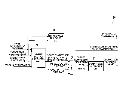
[0018] FIG. 2 is a block diagram illustrating a control unit of the fuel cell
system according to the first embodiment of this invention.
[0019] A control unit 70 of the fuel cell system according to this invention
includes a two-input/two-output FB control unit 71, a maximum selection
5
CA 02865877 2014-08-28
unit 72, a compressor FB control unit 73, and a bypass valve FB control unit
74.
[0020] The two-input/two-output FB control unit 71 determines two outputs
(air pressure regulating valve command value and target compressor intake
flow rate required by the stack) so that two inputs (stack supply flow rate F2
and stack inlet pressure P) converge to their respective target values (target
stack supply flow rate and target stack inlet pressure). Specifically,
calculation equations for modeling the system are set on the
two-input/two-output FB control unit 71, and the two-input/two-output FB
control unit 71 calculates the air pressure regulating valve command value
and the target compressor intake flow rate required by the stack based on
the calculation equations. It should be noted that the target compressor
intake flow rate required by the stack corresponds to "second flow rate
required from the compressor" of Claims. Moreover, the target stack supply
flow rate and the target stack inlet pressure are set based on a target output
required from the fuel cell stack.
[0021] The maximum selection unit 72 selects the maximum value out of the
target compressor intake flow rate required by the stack, a surge avoidance
flow rate, and a hydrogen dilution flow rate, and sets the maximum value as
a target compressor intake flow rate. Referring to FIGS. 3A and 3B, a
description is given of the surge avoidance flow rate and the hydrogen
dilution flow rate, and a reason for the configuration.
[0022] The cathode compressor 20 is a turbo compressor. The turbo
compressor has a characteristic illustrated in FIG. 3A, and is inhibited from
operating in an area (surge area) where a surge possibly occurs. For
6
CA 02865877 2014-08-28
example, a case where an operating point set based on the target output
required from the fuel cell stack is P11 (compressor supply flow rate Q11 and
pressure ratio before/after compressor r1) is now considered. The operating
point P11 exists in the surge area. If the compressor is operated at the
operating point P11, the surge may occur. In this case, it is thus necessary
to exit from the surge area by operating the compressor at an air flow rate
Q12 more than the air flow rate Q11 set based on the target output required
from the fuel cell stack. In other words, in this case, the air flow rate Q12
is
a lower limit flow rate for operating the compressor, and the lower limit flow
rate (compressor lower limit flow rate) is the surge avoidance flow rate. The
compressor needs to be operated at a flow rate more than the compressor
lower limit flow rate (surge avoidance flow rate).
[0023] Moreover, in the fuel cell system according to this invention, as
described above, the waste gas (hydrogen-off gas) which has not been
consumed for the power generation is diluted by the cathode gas, and is
discharge to the atmosphere. The air flow rate required for the dilution is
illustrated in FIG. 3B. When an output current required from the fuel cell
stack is 11, an air flow rate (air flow rate to be supplied to the fuel cell
stack)
necessary for the power generation is Q21. In contrast, when the output
current required from the fuel cell stack is 11, an air flow rate required for
diluting the hydrogen is Q22. In this case, the compressor thus needs to be
operated at the air flow rate Q22 more than the air flow rate Q21 required for
the power generation. In others words, in this case, the air flow rate Q22 is
a lower limit flow rate for operating the compressor, and the lower limit flow
rate (compressor lower limit flow rate) is the hydrogen dilution flow rate.
7
CA 02865877 2014-08-28
The compressor needs to be operated at a flow rate more than the
compressor lower limit flow rate (hydrogen dilution flow rate).
[0024] For those reasons, the maximum selection unit 72 selects the
maximum value out of the target compressor intake flow rate required by the
stack, the surge avoidance flow rate, and the hydrogen dilution flow rate,
and sets the maximum value as the target compressor intake flow rate.
[00251 It should be noted that 1\Q1 (=Q12-Q11) is necessary for avoiding the
surge, but is a surplus air flow rate for the power generation by the fuel
cell
stack. Moreover, AQ2 (=Q22-Q21) is necessary for diluting the hydrogen, but
is a surplus air flow rate for the power generation by the fuel cell stack. If
the surplus air is supplied to the fuel cell stack, the operability of the
fuel
cell stack may be adversely affected. Thus, the surplus air is not supplied
to the fuel cell stack, but is controlled to flow to the bypass flow passage
52.
[0026] FIG. 2 is now referred to again.
[0027] The compressor FB control unit 73 determines a compressor
command value so that the flow rate (compressor intake flow rate F1 or stack
supply flow rate F2) detected by the sensor converges to its target value
(target compressor intake flow rate). Specifically, the compressor FB control
unit 73 determines the compressor command value with feedback control (PI
control) depending on a component proportional to a difference of the sensor
rate from the target rate (target compressor intake flow rate) and a
component (integral component) acquired by the time integration of the
difference of the sensor rate from the target rate (target compressor intake
flow rate). It should be noted that when the cathode flow rate supplied to the
fuel cell stack is less than the compressor lower limit flow rate (in other
8
CA 02865877 2014-08-28
words, the surplus air needs to be bypassed), the compressor FB control
unit 73 determines the compressor command value so that the compressor
intake flow rate Fl converges to its target rate (target compressor intake
flow
rate). Moreover, when the cathode flow rate supplied to the fuel cell stack is
more than the compressor lower limit flow rate (in other words, the surplus
air does not exist, and the bypassing is not necessary), the compressor FB
control unit 73 determines the compressor command value so that the stack
supply flow rate F2 converges to its target rate (target stack supply flow
rate).
It should be noted that in this case, the surplus air does not exist and the
bypassing is not necessary, and the target stack supply flow rate is thus
equal to the target compressor intake flow rate.
[0028] The bypass valve FB control unit 74 determines a bypass valve
command value so that the stack supply flow rate F2 converges to its target
rate (target stack supply flow rate). Specifically, the bypass valve FB
control
unit 74 determines the bypass valve command value with feedback control
(PI control) depending on a component proportional to a difference of the
stack supply flow rate F2 from the target rate (target stack supply flow rate)
and a component (integral component) acquired by the time integration of
the difference of the stack supply flow rate F2 from the target rate (target
stack supply flow rate).
[0029] FIG. 4 is a chart illustrating effects of the first embodiment.
[0030] In a comparative mode (method disclosed in JP 2009-123550 A), as
described above, a bypass flow rate increases depending on, for example,
performance variations (individual variations) of a bypass valve and a
compressor, and the supply flow rate of the compressor is increased so as to
9
CA 02865877 2014-08-28
compensate for the variations as represented by the broken line of FIG. 4.
Thus, the power consumption of the compressor increases.
[0031] In contrast, in this embodiment, when the surplus air needs to be
bypassed, the compressor FB control unit 73 determines the compressor
command value so that the compressor intake flow rate Fl converges to its
target rate (target compressor intake flow rate). Then, the bypass valve FB
control unit 74 controls the bypass valve so that the stack supply flow rate
F2 converges to the target rate (target stack supply flow rate). This
configuration provides such an effect that the bypass valve and the
compressor operate the stack supply flow rate. The supply flow rate of the
compressor is prevented from increasing unnecessarily excessively, and the
bypass valve is opened accordingly, which prevents the power consumption
of the compressor from increasing uselessly.
[0032] Moreover, when the surplus air does not exist and the bypass is thus
unnecessary, the compressor command value is determined so that the
stack supply flow rate F2 converges to its target rate (target stack supply
flow rate). In this way, even if a variation exists in the bypass valve, the
stack supply flow rate can be controlled to reach the target rate. Further, in
addition to such an effect that the stack supply flow rate approaches the
target rate, such an effect that the supply flow rate from the compressor can
keep the restriction imposed by the lower limit value is provided. Then,
such an excellent effect that even if the variation exists in the bypass
valve,
the fuel efficiency is improved without increasing the power consumption of
the compressor is provided.
[0033] (Second embodiment)
CA 02865877 2014-08-28
FIG. 5 is a block diagram illustrating a control unit of the fuel cell
system according to a second embodiment of this invention.
[0034] In this embodiment, the opening degree of the bypass valve is
decreased when predetermined conditions are satisfied. Referring to the
control block diagram of FIG. 5, a description is given of specific details
thereof.
[0035] In this embodiment, the control unit includes a control block 75 for
carrying out bypass valve compulsory close control in addition to the control
blocks of the first embodiment.
[0036] The bypass valve compulsory close control 75 includes an addition
unit 751, a condition determination unit 752, an addition unit 753, a
condition determination unit 754, and a compulsory close flag output unit
755.
[0037] The addition unit 751 outputs a value acquired by adding a margin to
the compressor lower limit flow rate. The margin is not indispensable, and
a magnitude of the margin only needs to be appropriately set depending on
component specifications used for the system configuration, sensor errors,
and control design results of parts for acquiring the compressor flow rate
required by the stack.
[0038] The condition determination unit 752 determines whether the target
stack flow rate is more than the value acquired by adding the margin to the
compressor lower limit flow rate or not. The condition determination unit
752 outputs 1 as an output 1 when the determination result is affirmative.
The condition determination unit 752 outputs 0 as the output 1 when the
determination result is negative.
11
CA 02865877 2014-08-28
[0039] The addition unit 753 outputs a value acquired by adding a margin to
the compressor lower limit flow rate. The margin is not indispensable, and
a magnitude of the margin only needs to be appropriately set depending on
component specifications used for the system configuration, sensor errors,
and control design results of parts for acquiring the compressor flow rate
required by the stack.
[0040] The condition determination unit 754 determines whether the
compressor flow rate required by the stack is more than the value acquired
by adding the margin to the compressor lower limit flow rate or not. The
condition determination unit 754 outputs 1 as an output2 when the
determination result is affirmative. The condition determination unit 754
outputs 0 as the output2 when the determination result is negative.
[0041] The compulsory close flag output unit 755 carries out such control as
to compulsorily close the bypass valve when the output 1 of the condition
determination unit 752 is 1, or the output2 of the determination unit 754 is
1. The compulsory close flag output unit 755 releases the compulsory close
control of the bypass valve when the outputl of the condition determination
unit 752 is 0, and the output2 of the determination unit 754 is 0.
[0042] FIG. 6 is a timing chart illustrating effects of the second embodiment
provided when a power generation current increases.
[0043] Referring to FIG. 6, a description is particularly given of a case
where
the condition determination unit 752 outputs 1 as the output 1. Moreover,
basically, the control illustrated in FIG. 2 is cyclically carried out.
Moreover,
in order to promote understanding of the figure, respective lines are shifted
from each other so as not to overlap each other.
12
CA 02865877 2014-08-28
[0044] A power generation current required from the fuel cell stack is small
before a time tl/ (FIG. 6(A)), and an air flow rate q12 necessary for
realizing
the power generation current is thus small (FIG. 6(C)). Accordingly, the flow
rate of the compressor may be small, but the compressor cannot be operated
at a flow rate lower than the compressor lower limit flow rate. Then, the
compressor is operated at a compressor lower limit flow rate q11 (FIG. 6(B)).
Then, a flow rate q11-q12 surplus for the power generation is controlled to
flow to the bypass flow passage (FIG. 6(D)).
[0045] The power generation current required from the fuel cell stack
increases at the time t// (FIG. 6(A)), and a target rate (target stack flow
rate)
of the air flow rate necessary for realizing the power generation current
increases to q13 accordingly (FIG. 6(C)), and exceeds the compressor lower
limit flow rate. As a result, the condition determination unit 752 outputs 1
as the output 1, a compulsory close flag for the bypass valve is set to ON
(FIG.
6(E)), and the bypass valve passage flow rate is decreased in a shorter period
than that when the bypass valve close operation is not carried out.
[0046] Subsequently to the time t/1, the compressor command value is
generated by the FB control unit so that the stack supply flow rate follows
the target rate. Therefore, when the difference between the stack supply
flow rate and the target rate is large, the target compressor intake air flow
rate is increased by the integration operation of the FB control unit as time
elapses (FIG. 6(B)).
[0047] The stack supply flow rate reaches the target rate at a time t12. As a
result, the bypass valve and a compressor manipulated variable do not
change, and are brought into steady states.
13
CA 02865877 2014-08-28
[00481 On this occasion, if the bypass valve compulsory close control
illustrated in FIG. 5 is not carried out, the bypass valve close operation is
not carried out at the time t//, and the operation is thus slower than in the
case where the bypass valve compulsory close control is carried out.
Moreover, the stack supply flow rate matches the target value at the time t12,
and the manipulated variable of the FB controller for the compressor flow
rate thus stops changing (broken line of FIG. 6(B)). Then, the bypass flow
rate also remains in a large state (broken line of FIG. 6(D)). In this state,
the power consumption of the compressor is large (broken line of FIG. 6(F)).
In other words, in this state, the supply flow rate of the compressor is
increased unnecessarily excessively, resulting in an unnecessary increase in
power consumption of the compressor.
[0049] In contrast, in this embodiment, the bypass valve compulsory close
control is carried out to avoid the retention of the bypass valve flow rate,
and
the bypass flow rate decreases (solid line of FIG. 6(D)). As described above,
basically, the control illustrated in FIG. 2 is cyclically carried out. Even
when a state where the bypass flow rate is possibly retained occurs, the
bypass valve compulsory close control is carried out, resulting in a decrease
in bypass flow rate. The decrease affects the stack supply flow rate and the
stack inlet pressure. When the control block diagram of FIG. 2 is cyclically
carried out as a result, subsequently, the opening degree of the bypass valve
decreases, resulting in a decrease in bypass flow rate. As a result, the
compressor flow rate decreases as represented by the solid line of FIG. 6(B).
Thus, the power consumption of the compressor decreases (solid line of FIG.
6(F)), a state where the power consumption is low continues after a time t13,
14
CA 02865877 2014-08-28
and the power consumption of the compressor is prevented from
unnecessarily increasing.
[0050] When a condition where a bypass valve manipulated variable is 0
corresponds to an operation of closing the bypass valve to decrease the
bypass flow rate, the bypass valve close operation includes, for example, a
method of multiplying a previous value of the integration operation of the FB
controller for calculating the bypass valve manipulated variable by a scale
factor less than one for forgetting when the compulsory close flag for the
bypass valve is set to ON, and a method of increasing, at a predetermined
rate, the difference acquired by subtracting the bypass valve passing flow
rate out of the differences input to the FB controller, fixing the difference
at a
predetermined difference, or correcting the difference to a predetermined
difference or less. Those methods are represented by flowcharts illustrated
in FIGS. 7A and 7B.
[0051] FIG. 8 is a timing chart illustrating effects of the second embodiment
provided when the power generation current decreases.
[0052] The power generation current required from the fuel cell stack is large
before a time t21 (FIG. 8(A)), and an air flow rate q22 necessary for
realizing
the power generation current is thus large, and is more than a compressor
lower limit flow rate q21 (FIG. 8(B)).
[0053] The power generation current required from the fuel cell stack
decreases at the time t21 (FIG. 8(A)), and the target rate (target stack flow
rate) of the air flow rate necessary for realizing the power generation
current
decreases to q23 accordingly, and decreases below the compressor lower
limit flow rate (FIG. 8(B)). Accordingly, the flow rate of the compressor may
CA 02865877 2014-08-28
be small, but the compressor cannot be operated at a flow rate lower than
the compressor lower limit flow rate. Then, the compressor is operated at
the compressor lower limit flow rate as the target compressor intake flow
rate (FIG. 8(B)).
[0054] The compressor intake flow rate (detected value) matches the target
compressor intake flow rate at a time t22. The cathode gas does not need to
be bypassed, and the bypass flow rate is thus zero (FIG. 8(C)). Accordingly,
the stack supply flow rate (detected value) matches the compressor intake
flow rate (detected value).
[0055] After the stack supply flow rate reaches the target rate, when the
control block illustrated in FIG. 2 is cyclically carried out without the
bypass
valve compulsory close control illustrated in FIG. 5, the target compressor
intake flow rate is maintained at a constant level as represented by the
broken line after a time t23, and as a result, a surplus flow rate, which is
originally unnecessary for supply to the stack, may be bypassed. In this
state, the power consumption of the compressor is large (broken line of FIG.
8(E)). In other words, in this state, the supply flow rate of the compressor
is
increased unnecessarily excessively, resulting in an unnecessary increase in
power consumption of the compressor.
[0056] In contrast, in this embodiment, the bypass valve compulsory close
control is carried out, thereby always maintaining the bypass flow rate to
zero. As a result, the target compressor intake flow rate decreases so that
the stack supply flow rate reaches the target rate as illustrated in FIG.
8(B).
Thus, the power consumption of the compressor decreases (solid line of FIG.
8(E)).
16
CA 02865877 2015-12-24
=
[0057] Even after the stack supply flow rate reaches the target rate at a time
t24, the power consumption of the compressor is low, and the power
consumption of the compressor is thus prevented from unnecessarily
increasing.
[0058] Though a description has been given of the embodiments of this
invention, the above-mentioned embodiments describe only a part of
application examples of this invention, and is not intended to limit the
technical scope of this invention to the specific configurations of the
above-mentioned embodiments.
[0059] For example, one of the above-mentioned embodiments may be
combined with another of the above-mentioned embodiments as appropriate.
17