Note: Descriptions are shown in the official language in which they were submitted.
CA 02866257 2014-09-03
WO 2013/134624
PCMJS2013/029833
SYSTEM AND METHOD FOR DELIVERING TREATMENT FLUID
BACKGROUND
[0001] The statements in this section merely provide background information
related to
the present disclosure and may not constitute prior art.
[0002] In the recovery of hydrocarbons from subterranean formations, it is
often
necessary to apply various treatment procedures to the well to improve the
life and/or
the productivity of the well. Examples of the treatment procedures include,
but are not
limited to, cementing, gravel packing, hydraulic fracturing, and acidizing.
Particularly, in
formations with low permeability, it is common to fracture the hydrocarbon-
bearing
formation to provide flow channels. These flow channels facilitate movement of
the
hydrocarbons to the wellbore so that the hydrocarbons may be recovered from
the well.
[0003] Fracturing has historically been an operation where the materials that
were going
to be pumped were prepared on location. Deliveries of liquids, proppant, and
chemicals
were all accomplished before the job began. Specialized storage equipment was
normally used for handling the large quantities of materials, such as sand
chiefs made
by Besser. Similarly, specialized tanks such as water tanks and frac tanks
were used for
liquids. These tanks are typically the largest possible volume that can be
legally
transported down the road without a permit. Once everything was ready, more
specialized equipment was used to prepare gel, mix in proppant, dose with
chemicals,
and deliver the resulting fluid to the fracturing pumps under positive
pressure. All of
these specialized well site vehicles and units are expensive, and lead to a
very large
footprint on location.
[0004] Fig. 1A illustrates a wellsite configuration 9 that is typically used
in current land-
based fracturing operations. The proppant is contained in sand trailers 10 and
11.
Water tanks 12, 13, 14, 15, 16, 17, 18, 19, 20, 21, 22, 23, 24, and 25 are
arranged along
one side of the operation site. Hopper 30 receives sand from the sand trailers
10,11 and
distributes it into the mixers 26, 28. Blenders 33, 36 are provided to blend
the carrier
medium (such as brine, viscosified fluids, etc.) with the proppant and then
transferred to
manifolds 31, 32. The final mixed and blended slurry, or frac fluid, is then
transferred to
1
CA 02866257 2014-09-03
WO 2013/134624
PCT/US2013/029833
the pump trucks 27, 29, and routed at high pressure through treating lines 34
to rig 35,
and then pumped downhole.
[0005] Referencing to Fig. 1B, a conventional fracturing operation 100 is
illustrated
schematically. The operation 100 includes a water tank 102 and a polymer
supplier 104.
The water tank is any base fluid including, for example, brine. The operation
100 may
include a precision continuous mixer 106. In certain embodiments, the
precision
continuous mixer 106 is replaced by an operation 100 where the polymer is
fully mixed
and hydrated in the water tank 102. It can be seen that, where the polymer is
pre-
batched, very little flexibility to the size of the fracturing operation is
available. For
example, if an early screen-out occurs, a large amount of fracturing fluid is
wasted and
must be disposed. The operation 100 further includes an operation 108 to
slowly agitate
and hydrate the fracturing fluid, which may occur within a residence vessel or
within a
properly sized precision continuous mixer 106. The operation 100 further
includes a
proppant 110 mixed with the hydrated fluid, for example at a high-speed
blender 112
that provides the proppant laden slurry to fracturing pumps. The operation 100
further
includes an operation 114 to pump the slurry downhole.
[0006] It can be seen from the operation 100 that various equipment is
required at the
location, including the water tanks, a chemical truck or other vehicle
carrying the polymer
and/or other additives, a continuous mixer, a proppant vehicle (sand truck,
sand chief,
etc.), a blender (e.g. a POD blender), and various fracturing pumps. In
some
embodiments, the continuous mixer may be replaced with equipment and time to
batch
mix the fracturing fluid into the water tanks in advance, increasing the
operational cost,
reducing the flexibility of the fracturing treatment, and increasing the
physical footprint of
the fracturing operation. Also, a large amount of water is needed for a
fracturing
operation, which leads to the generation of a large amount of flowback fluid.
The
storage, management, and disposal of the flowback fluid are expensive and
environmentally challenging.
[0007] Conventional logistical practices of a hydrocarbon bearing field (e.g.
oilfield,
natural gas field, etc.) vary over the life cycle of the field. After
placement of the well,
equipment delivery to the wellsite requires the construction of a road (often
temporary),
and delivery of various treatment fluids to the wellsite location. Treatment
fluids are
typically brought in by truck. After treatment of the well, produced fluids
are brought to
2
CA 02866257 2014-09-03
WO 2013/134624
PCT/US2013/029833
surface and must be brought into the commercial system through some delivery
system.
Initially some returned treatment fluids may need to be stored, recovered, or
otherwise
disposed. Produced fluids can be stored on-site and periodically picked up,
brought to a
collection facility near the wellsite, or be transferred into long range
delivery systems
such as pipelines. Some production fluid treatment and/or separation may be
provided
at the wellsite. During the life cycle of production of a well, periodic
treatments may be
indicated to increase production, remove well damage, or to treat for issues
such as
corrosion, paraffin buildup, water production, or other issues. Some zones
within a
wellbore may be shut in after producing for a time, and/or additional zones
within the
wellbore may be opened and/or stimulated, essentially requiring the types of
treatment
at the wellsite that more typically occur with newly drilled wells. After a
formation has
been produced for a period of time, one or more wells in the field may be
converted or
initially drilled to be injection wells, which may provide reservoir pressure
support,
flushing of fluids to producer wells, and/or fluid disposal.
[0008] As indicated by conventional logistical practices, a number of
challenges are
presented in the management of a well and a field over the life cycle of the
field. Many
conventionally managed fields suffer from one or more of the following
challenges.
Multiple types of fluid may be delivered to a wellsite over a number of years,
which may
require the building of temporary roads on multiple occasions or the
maintenance of
roads where land might otherwise be more productive. Production systems
require long-
range transport of excess fluids (e.g. water present in produced oil) and/or
multiple units
of separation or other production fluid treatment equipment. Injector wells
require
delivery of injection fluid to the well, and may require various types of
fluid delivered to
the wellsite over a number of years for various treatment operations. Wells
and/or zones
within wells may be converted from production to injection during the life
cycle of the
well. Additional zones opened within a well may require additional fluids
delivered to the
well, addition of separation or other production fluid treatment equipment to
the wellsite,
and/or a change in the type of separation or other production fluid treatment
equipment
as the produced fluids change over time or from distinct zones being produced.
[0009] The current application addresses one or more of the problems
associated with
conventional fracturing operations and/or conventional logistical practices of
a
hydrocarbon bearing formation.
3
,81782263
=
SUMMARY
[0010] According to an embodiment of the present invention, there is provided
a
system, comprising: a regional blending facility comprising: a plurality of
bulk
receiving facilities, each of the bulk receiving facilities structured to
receive and store
a distinct solid particle type having a distinct size modality, wherein the
solid particle
types in each of the bulk receiving facilities has a distinct size modality
from at least
one of the other solid particle types in the bulk receiving facilities; a bulk
moving
device that transfers the solid particles between the bulk receiving
facilities and one
of a first vessel and a mixer, the first vessel configured for blending or
continuously
receiving or both; a carrying medium vessel; the mixer structured to: receive
the solid
particles from one of the first vessel and the bulk moving device; receive a
carrying
medium from the carrying medium vessel; mix the solid particles with the
carrying
medium; and provide a mixed treatment fluid; and a fluid conduit that fluidly
couples a
wellsite location with the regional blending facility, the fluid conduit
structured to
deliver at least one of: the mixed treatment fluid to the wellsite; and
produced fluid
from a wellbore positioned at the wellsite to the regional blending facility.
[0010a] According to another embodiment of the present invention, there is
provided
a system, comprising: a regional blending facility comprising: a mixed
treatment fluid
subsystem comprising a solid bulk receiving facility and a mixer, the mixed
treatment
fluid subsystem configured to provide a mixed treatment fluid therefrom, the
regional
blending facility fluidly coupled to a plurality of wellsite locations; and a
production
fluid processing subsystem configured to process an amount of production
fluid; and
a controller, comprising: a treatment design module structured to interpret a
treatment
schedule comprising a fluid recipe and fluid preparation conditions; a
facility control
module structured to provide facility commands in response to the fluid recipe
and
fluid preparation conditions; a production management module structured to
interpret
a production status corresponding to one of the wellsite locations and to
provide a
facility production communication in response to the production status; and a
producer management module structured to interpret a producer treatment
schedule
and to determine producer operations in response to the producer treatment
4
CA 2866257 2019-12-18
,,81782263
=
schedule, the system further comprising a producer treatment subsystem
configured
to treat produced fluid in response to the producer treatment schedule,
wherein the
mixed treatment fluid subsystem is responsive to the facility commands,
wherein the
production fluid processing subsystem is responsive to the facility production
communication, and wherein the producer treatment fluid subsystem is
responsive to
the producer operations, wherein the regional blending facility further
comprises a
plurality of bulk receiving facilities, each of the bulk receiving facilities
structured to
receive and store a distinct solid particle type having a distinct size
modality, wherein
the solid particle types in each of the bulk receiving facilities has a
distinct size
modality from at least one of the other solid particle types in the bulk
receiving
facilities.
[0010b] According to another embodiment of the present invention, there is
provided
a method, comprising: interpreting a treatment schedule for a wellsite;
providing a
mixed treatment fluid at a regional blending facility in response to the
treatment
schedule by combining at least a solid particulate and a fluid; co-locating
the regional
blending facility with a supply facility at the wellsite, wherein providing
the mixed
treatment fluid further comprises transferring at least one amount of solid
particulates
from the supply facility to the regional blending facility; moving the mixed
treatment
fluid through a fluid conduit from the regional blending facility to the
wellsite;
producing a fluid from a wellbore at the wellsite; and moving the produced
fluid
through the fluid conduit from the wellsite to the regional blending facility,
wherein the
regional blending facility further comprises a plurality of bulk receiving
facilities, each
of the bulk receiving facilities structured to receive and store a distinct
solid particle
type having a distinct size modality, wherein the solid particle types in each
of the
bulk receiving facilities has a distinct size modality from at least one of
the other solid
particle types in the bulk receiving facilities.
[0011] In certain embodiments, a system is disclosed which includes a regional
blending facility having a number of bulk receiving facilities, where each
bulk
receiving facility receives and stores a particle type having a distinct size
modality.
The regional blending facility includes a bulk moving device that transfers
particles
4a
CA 2866257 2019-12-18
.81782263
=
between the bulk receiving facilities and a blending/continuously receiving
vessel
and/or a mixer, and a carrying medium vessel. The mixer receives particles
from the
blending/continuously receiving vessel and/or the bulk moving device, receives
a
carrying medium from the carrying medium vessel, mixes the particles with the
carrying medium, and provides a mixed treatment fluid. The system further
includes a
fluid conduit that fluidly couples a wellsite location with the regional
blending facility,
where the fluid conduit is capable to deliver the mixed treatment fluid to the
wellsite,
and/or capable to deliver produced fluid from a wellbore positioned at the
wellsite to
the regional blending facility.
[0011a] In certain embodiments, a system is disclosed which includes a
regional
blending facility having a number of bulk receiving facilities, where each
bulk
receiving facility receives and stores a particle type having a distinct size
modality.
The regional blending facility includes a bulk moving device that transfers
particles
between the bulk' receiving facilities and a blending/continuously receiving
vessel
and/or a mixer, and a carrying medium vessel. The mixer receives particles
from the
blending/continuously receiving vessel and/or the bulk moving device, receives
a
carrying medium from the carrying medium vessel, mixes the particles with the
carrying medium, and provides a mixed treatment fluid. The system further
includes
one or more local storage hub that receives the mixed treatment fluid from the
regional blending facility and temporarily stores the mixed treatment fluid
before
usage. The system may further include a fluid conduit that fluidly couples a
wellsite
location with the local storage hub, where the fluid conduit is capable to
deliver the
mixed treatment fluid to the wellsite, and/or capable to deliver produced
fluid from a
wellbore positioned at the wellsite to the local storage hub. Similarly, the
system may
further include a fluid conduit that fluidly couples the regional blending
facility with the
local storage hub, where the fluid conduit is capable to deliver the mixed
treatment
fluid from the regional blending facility to the local storage hub, and/or
capable to
deliver produced fluid from a local storage hub to the regional blending
facility.
4b
CA 2866257 2019-12-18
CA 02866257 2014-09-03
WO 2013/134624
PCT/US2013/029833
[0012] In certain further embodiments, the system may include a supply
facility that
provides at least one bulk material to the bulk receiving facilities, where
the supply
facility is co-located with the regional blending facility. In some
embodiments, the bulk
material is a particulate and the supply facility may be a mine, a pit, a
digging operation,
and/or a quarry. In some embodiments, the bulk material is a liquid and the
supply
facility may be a pool, a lake, a pond, a sea, or other source of the liquid.
The system
may include a production fluid treatment facility that receives an amount of
production
fluid from the wellbore through the fluid conduit, where the production fluid
treatment
facility further performs an operation to separate the production fluid, to
settle the
production fluid, to store the production fluid, to transmit the production
fluid. The
system may include the production fluid treatment facility performing an
operation to
route at least a portion of the production fluid to a second fluid conduit
that fluidly
couples a second wellsite location with the regional blending facility, where
the system
further includes a second wellbore positioned at the second wellsite, and
where the
production fluid treatment facility is co-located with the regional blending
facility.
[0013] In certain further embodiments, the system may include the regional
blending
facility further providing the mixed treatment fluid to the wellsite on a
continuous basis
and/or on a real-time basis, and may include the fluid conduit capable to
selectively
deliver both the mixed treatment fluid and the produced fluid at distinct
times. An
example system further includes the mixed treatment fluid being a high solids
content
fluid.
[0014] In certain further embodiments, the system may include further a
production fluid
treatment facility that receives an amount of production fluid from the
wellbore through
the fluid conduit, that separates the production fluid into a first production
fluid portion
and a second production fluid portion, that transmits the first production
fluid portion, and
that routes the second production fluid portion to a second fluid conduit that
fluidly
couples a second wellsite location with the regional blending facility. The
system further
includes a second wellbore positioned at the second wellsite, where the
production fluid
treatment facility is co-located with the regional blending facility. An
example system
further includes the regional blending facility further providing a well
maintenance
treatment fluid to one of the fluid conduit and the second fluid conduit,
wherein the well
maintenance treatment fluid includes a mixed treatment fluid, a matrix
treatment fluid, a
water control treatment fluid, a fluid diversion treatment fluid, a
stimulation treatment
CA 02866257 2014-09-03
WO 2013/134624
PCT/US2013/029833
fluid, a paraffin control treatment fluid, an asphaltene control treatment
fluid, a gas lift
fluid, and/or a particulate consolidation treatment fluid.
[0015] In certain embodiments, a system is disclosed including a regional
blending
facility including a subsystem for providing a mixed treatment fluid, where
the regional
blending facility fluidly is coupled to a plurality of wellsite locations. The
system includes
a controller having a treatment design module that interprets a treatment
schedule
having a fluid recipe and fluid preparation conditions; a facility control
module that
provides facility commands in response to the fluid recipe and fluid
preparation
conditions, where the subsystem for providing the mixed treatment fluid is
responsive to
the facility commands to provide the mixed treatment fluid to the wellsite on
at least one
of a continuous and a real-time basis.
[0016] In certain further embodiments, the system may include the mixed
treatment fluid
being a high solids content fluid (HSCF) having a number of particle size
modalities, and
may further include a supply facility that provides at least one particulate
material to the
bulk receiving facilities, where the supply facility is co-located with the
regional blending
facility, and where the at least one particulate material includes at least
one of the
number of particle size modalities.
[0017] In certain embodiments, a system includes a regional blending facility
having a
subsystem for providing a mixed treatment fluid, the regional blending
facility fluidly
coupled to a number of wellsite locations, and a subsystem for processing a
production
fluid amount. The system includes a controller having a treatment design
module that
interprets a treatment schedule including a fluid recipe and fluid preparation
conditions, a
facility control module that provides facility commands in response to the
fluid recipe and
fluid preparation conditions, and a production management module that
interprets a
production status corresponding to one of the wellsite locations and provides
a facility
production communication in response to the production status. The subsystem
for
providing the mixed treatment fluid is responsive to the facility commands,
and the
subsystem for processing the production fluid amount is responsive to the
facility
production command.
[0018] In certain further embodiments, the controller further includes a
producer
management module that interprets a producer treatment schedule and determines
producer operations in response to the producer treatment schedule. The system
6
CA 02866257 2014-09-03
WO 2013/134624
PCT/US2013/029833
further includes a subsystem for providing a producer treatment fluid in
response to the
producer treatment schedule, where the subsystem for providing the producer
treatment
fluid is responsive to the producer operations. The controller may further
include an
injector management module that interprets an injector treatment schedule and
determines injector operations in response to the injector treatment schedule,
where the
system further includes a subsystem for providing an injector treatment fluid
in response
to the injector treatment schedule, and where the subsystem for providing the
injector
treatment fluid is responsive to the injector operations.
[0019] In certain further embodiments, the system includes each of the
wellsites fluidly
coupled to the regional blending facility with at least one fluid conduit,
where each fluid
conduit is capable to deliver the mixed treatment fluid to the wellsite,
produced fluid from
a wellbore positioned at the wellsite to the regional blending facility,
and/or injection fluid
to the wellsite. The system may include the facility production command being
a
separation command, where the injection fluid includes a separated portion of
a
produced fluid. The system may include a supply facility that provides at
least one
particulate material to the bulk receiving facilities, where the supply
facility is co-located
with the regional blending facility, and the controller includes a supply
management
module that interprets a supply status and the treatment schedule, a producer
treatment
schedule, and/or an injector treatment schedule, where the supply management
module
further provides a facility supply communication in response to the treatment
schedule, a
producer treatment schedule, and/or an injector treatment schedule, and where
the
supply facility is responsive to the facility supply communication.
[0020] In certain embodiments, a method includes interpreting a treatment
schedule for
a wellsite, providing a mixed treatment fluid at a regional blending facility
in response to
the treatment schedule, moving the mixed treatment fluid through a fluid
conduit from the
regional blending facility to the wellsite, producing a fluid from a wellbore
at the wellsite,
and moving the produced fluid through the fluid conduit from the wellsite to
the regional
blending facility. In certain further embodiments, the method may include
separating the
production fluid into a first production fluid portion and a second production
fluid portion,
transmitting the first production fluid portion, and routing the second
production fluid
portion to a second fluid conduit that fluidly couples a second wellsite
location with the
regional blending facility, and may further include injecting the second
production fluid
portion into a second wellbore positioned at the second wellsite. In certain
further
7
CA 02866257 2014-09-03
WO 2013/134624
PCT/US2013/029833
embodiments, the method may include co-locating the regional blend facility
with a
supply facility, where the providing the mixed treatment fluid further
includes transferring
at least one amount of particulates from the supply facility to the regional
blending
facility; providing the mixed treatment fluid by continuously providing the
mixed treatment
fluid during treatment operations at the wellsite; and/or providing the mixed
treatment
fluid by providing the mixed treatment fluid in real-time during treatment
operations at the
wellsite.
8
CA 02866257 2014-09-03
WO 2013/134624
PCT/US2013/029833
BRIEF DESCRIPTION OF THE DRAWINGS
[0021] These and other features and advantages will be better understood by
reference
to the following detailed description when considered in conjunction with the
accompanying drawings.
[0022] FIG. 1A is a schematic representation of the equipment configuration of
a
conventional fracturing operation.
[0023] FIG. 1B is a schematic representation of a conventional fracturing
operation.
[0024] Fig. 2 is a schematic representation of a treatment fluid preparation
system
according to some embodiments of the current application.
[0025] Fig. 3 is a schematic representation of a treatment fluid preparation
system and a
particulate supply facility according to some embodiments of the current
application.
[0026] FIG. 4 is a schematic representation of a treatment fluid preparation
facility
according to some embodiments of the current application.
[0027] Fig. 5 is a schematic representation of a treatment fluid preparation
facility and a
fluid line coupling the treatment fluid preparation facility to a wellsite.
[0028] Fig. 6 is a schematic representation of a treatment fluid preparation
facility having
a production fluid management facility, and a fluid line coupling the
treatment fluid
preparation facility to a wellsite.
[0029] Fig. 7 is a schematic representation of a treatment fluid preparation
facility
coupled to a production fluid management facility, and a fluid line coupling
the treatment
fluid preparation facility to a wellsite.
[0030] Fig. 8 is a schematic representation of a treatment fluid preparation
facility having
an injection fluid management system, coupled to an auxiliary facility, and
fluid lines
coupling the treatment fluid preparation facility to a number of different
well types.
[0031] FIG. 9 is a schematic representation of a blending plant for preparing
treatment
fluids according to some embodiments of the current application.
[0032] FIG. 10 is a schematic representation of the use of the treatment fluid
at a
wellsite according to some embodiments of the current application.
9
CA 02866257 2014-09-03
WO 2013/134624
PCT/US2013/029833
[0033] FIG. 11 is a schematic representation of a treatment fluid preparation
system
according to some embodiments of the current application.
[0034] FIG. 12 is another schematic representation of a treatment fluid
preparation
system according to some embodiments of the current application.
[0035] FIG. 13A is a schematic representation of another embodiment of a
treatment
fluid preparation system.
[0036] FIG. 13B is a schematic representation of a further embodiment of a
treatment
fluid preparation system.
[0037] FIG. 14 is a schematic representation of still another embodiment of a
treatment
fluid preparation system.
[0038] FIG. 15 is a schematic representation of a control unit for the
treatment fluid
preparation system according to some embodiments of the current application.
DETAILED DESCRIPTION OF SOME ILLUSTRATIVE EMBODIMENTS
[0039] For the purposes of promoting an understanding of the principles of the
disclosure, reference will now be made to the embodiments illustrated in the
drawings
and specific language will be used to describe the same. It will nevertheless
be
understood that no limitation of the scope of the claimed subject matter is
thereby
intended, any alterations and further modifications in the illustrated
embodiments, and
any further applications of the principles of the application as illustrated
therein as would
normally occur to one skilled in the art to which the disclosure relates are
contemplated
herein.
[0040] The schematic flow descriptions which follow provide illustrative
embodiments of
performing procedures for preparing and delivering treatment fluid or
treatment fluid
precursor to a wellsite. Operations illustrated are understood to be examples
only, and
operations may be combined or divided, and added or removed, as well as re-
ordered in
whole or part, unless stated explicitly to the contrary herein. Certain
operations
illustrated may be implemented by a computer executing a computer program
product
on a computer readable medium, where the computer program product comprises
CA 02866257 2014-09-03
WO 2013/134624
PCT/US2013/029833
instructions causing the computer to execute one or more of the operations, or
to issue
commands to other devices to execute one or more of the operations.
[0041] In particular, it should be understood that, although a substantial
portion of the
following detailed description is provided in the context of oilfield
hydraulic fracturing
operations, other oilfield operations such as cementing, gravel packing, etc.
can utilize
and benefit from the disclosure of the current application as well. All
variations that can
be readily perceived by people skilled in the art after reviewing the current
application
should be considered as within the scope of the current application.
[0042] As used herein, the term "treatment fluid" should be understood
broadly.
Treatment fluids include liquid, a solid, a gas, and combinations thereof, as
will be
appreciated by those skilled in the art. A treatment fluid may take the form
of a solution,
an emulsion, a slurry, or any other form as will be appreciated by those
skilled in the art.
In some embodiments, the treatment fluid may contain a carrying medium and a
substance that is substantially immiscible therein. The carrying medium may be
any
matter that is substantially continuous under a given condition. Examples of
the carrying
medium include, but are not limited to, water, hydrocarbon, gas, liquefied
gas, etc. In
some embodiments, the carrying medium may optionally include a viscosifying
agent.
Some non-limiting examples of the carrying medium include hydratable gels
(e.g. guars,
poly-saccharides, xanthan, diutan, hydroxy-ethyl-cellulose, etc.), a cross-
linked
hydratable gel, a viscosified acid (e.g. gel-based), an emulsified acid (e.g.
oil outer
phase or oil internal phase), an energized fluid (e.g. an N2 or CO2 based
foam), a
viscoelastic surfactant (VES) viscosified fluid, and an oil-based fluid
including a gelled,
foamed, or otherwise viscosified oil. Additionally, the carrier medium may be
a brine,
and/or may include a brine. The substantially immiscible substance can be any
matter
that only dissolves or otherwise becomes a constituent portion of the carrying
fluid under
a given condition for less than 10%, sometimes less than 20%, of the weight of
substance when it is not in contact of the carrying medium. Examples of
substantially
immiscible substance include, but are not limited to, proppant, salt,
emulsified
hydrocarbon droplets, etc.
[0043] As used herein, the term "pump-ready" should be understood broadly. In
certain
embodiments, a pump-ready treatment fluid means the treatment fluid is fully
prepared
and can be pumped downhole without being further processed. In some other
11
CA 02866257 2014-09-03
WO 2013/134624
PCT/US2013/029833
embodiments, the pump-ready treatment fluid means the fluid is substantially
ready to
be pumped downhole except that a further dilution may be needed before pumping
or
one or more minor additives need to be added before the fluid is pumped
downhole. In
such an event, the pump-ready treatment fluid may also be called a pump-ready
treatment fluid precursor. In some further embodiments, the pump-ready
treatment fluid
may be a fluid that is substantially ready to be pumped downhole except that
certain
incidental procedures are applied to the treatment fluid before pumping, such
as low-
speed agitation, heating or cooling under exceptionally cold or hot climate,
etc.
[0044] In certain embodiments, the pump-ready treatment fluid is a high
particle content
fluid where the volume fraction of the carrying medium in the pump-ready
treatment fluid
is less than 60% of the total volume of the pump-ready treatment fluid. Stated
in another
way, in such embodiments, the volume fraction of the immiscible substance in
the pump-
ready treatment fluid is equal to or more than 40% of the total volume of the
pump-ready
treatment fluid. In certain other embodiments, the volume fraction of the
carrying
medium is less than 50% of the pump-ready treatment fluid, with the immiscible
substance making up 50% or more volume fraction of the pump-ready treatment
fluid. In
certain additional embodiments, the pump-ready treatment fluid has a volume
fraction of
the carrying medium that is less than 40% and a volume fraction of the
immiscible
substance that is 60% or more. In certain further embodiments, the pump-ready
treatment fluid has a volume fraction of the carrying medium that is less than
30% and a
volume fraction of the immiscible substance that is 70% or more. In certain
even further
embodiments, the pump-ready treatment fluid has a volume fraction of the
carrying
medium that is less than 20% and a volume fraction of the immiscible substance
that is
80% or more. In certain additionally further embodiments, the pump-ready
treatment
fluid has a volume fraction of the carrying medium that is less than 10% and a
volume
fraction of the immiscible substance that is 90% or more.
[0045] In some cases, the immiscible substance contains a single particle size
or
particle size distribution (i.e. monomode). In some
other cases, the immiscible
substance contains a plurality of particles having distinct sizes or particles
size
distributions (i.e. multi-modes). As used herein, the terms distinct particle
sizes, distinct
particle size distribution, or multi-modes or multimodal, mean that each of
the plurality of
particles has a unique volume-averaged particle size distribution (PSD) mode.
That is,
statistically, the particle size distributions of different particles appear
as distinct peaks
12
CA 02866257 2014-09-03
WO 2013/134624
PCT/US2013/029833
(or "modes") in a continuous probability distribution function. For example, a
mixture of
two particles having normal distribution of particle sizes with similar
variability is
considered a bimodal particle mixture if their respective means differ by more
than the
sum of their respective standard deviations, and/or if their respective means
differ by a
statistically significant amount. In certain
embodiments, the immiscible substance
contains a bimodal mixture of two particles; in certain other embodiments, the
immiscible
substance contains a trimodal mixture of three particles; in certain
additional
embodiments, the immiscible substance contains a tetramodal mixture of four
particles;
in certain further embodiments, the immiscible substance contains a pentamodal
mixture
of five particles.
[0046] In some embodiments, the immiscible substance has a packed volume
fraction
(PVF) of 64% or higher. As used herein, the term "packed volume fraction, or
PVF,
means a theoretical calculation of the most likely configuration of particles
of various
sizes. It can be defined as the volume occupied by the particles divided by
the total
volume of the particles plus the void space between the particles. In certain
other
embodiments, the immiscible substance has a packed volume fraction (PVF) of
74% or
higher. In certain additional embodiments, the immiscible substance has a
packed
volume fraction (PVF) of 87% or higher.
[0047] As used herein, the terms "particle" or "particulate" should be
construed broadly.
In certain embodiments, the particle or particulate is substantially
spherical. In some
certain embodiments, the particle or particulate is not substantially
spherical. For
example, the particle or particulate may have an aspect ratio, defined as the
ratio of the
longest dimension of the particle to the shortest dimension of the particle,
of more than
2, 3, 4, 5 or 6. Examples of such non-spherical particles include, but are not
limited to,
fibers, flakes, discs, rods, stars, etc. Similarly, in some embodiments, the
particle(s) or
particulate(s) of the current application are solid such as proppant, sands,
ceramics,
crystals, salts, etc.; however, in some other embodiments, the particle(s) or
particulate(s)
can be liquid, gas, foams, emulsified droplets, etc. Moreover, in some
embodiments, the
particle(s) or particulate(s) of the current application are substantially
stable and do not
change shape or form over an extended period of time, temperature, or
pressure; in
some other embodiments, the particle(s) or particulate(s) of the current
application are
degradable, dissolvable, deformable, meltable, sublimeable, or otherwise
capable of
13
81782263
being changed in shape, state, or structure. All such variations should be
considered
within the scope of the current application.
[0048] Certain examples of treatment fluids, carrying media, and particles
that can be
used in the current application are illustrated in US7784541, US2011/0005760,
US2010/0300688, US7923415, US2012/0000651, US2012/0000641, US2011/0155371.
[0049] In certain embodiments, the pump-ready treatment fluid is a fracturing
fluid. In
certain embodiments, the pump-ready fracturing fluid includes all ingredients,
Including
proppant, for the fracturing treatment in a form that is directly deliverable
to the suction
side of a fracturing pump. The procedure may further include an operation to
deliver the
pump-ready fracturing fluid to a location operationally coupled to a wellsite,
and an
operation to provide the pump-ready fracturing fluid directly to a pump Inlet.
The
procedure may further include an operation to pump the pump-ready fracturing
fluid into
a wellbore to initiate or propagate a fracture in the subterranean formation.
[0050] As used herein, the term "supply facility" should be understood
broadly. A supply
facility Is any facility that provides one or more particles or particulate
materials. A
supply facility may Include a mine, a pit, a quarry, a digging operation,
and/or an
interface to any of these. A supply facility may include only a portion of an
overall facility
including the mine or other operation to retrieve the particles or particulate
materials, and
may specifically include, but not be limited to, a transportation interface
portion.
[0051] As used herein, the term co-located" should be understood broadly. Co-
located
as used herein includes facilities that share the same building or other
infrastructure,
such as roads, parking areas, fences, areas covered within the same local area
network
(LAN), facilities referenced by the same location call sign or nickname,
and/or facilities
positioned together in any other operational sense. In certain embodiments, co-
located
facilities are facilities that are within walking distance of each other,
facilities wherein
materials travel between the facilities via equipment or other processes
rather than
vehicle transport, and/or facilities having the controls of relevant equipment
of each
facility being co-located in any other sense described herein. In certain
embodiments,
only relevant portions of each of the co-located facilities are positioned
together as
otherwise described herein.
14
CA 2866257 2020-03-10
CA 02866257 2014-09-03
WO 2013/134624
PCT/US2013/029833
[0052] As used herein, the term "production fluid treatment facility" should
be
understood broadly. A production fluid treatment facility includes any
equipment that is
utilized in the treatment, storage, or transmission of a produced fluid from a
well.
Example and non-limiting equipment included as a production fluid treatment
facility
includes a flare device, a settling tank, a separator of any kind, a holding
tank, a reactor
vessel, a distillation column, transmission lines, and/or valves, gauges, or
detectors (e.g.
pressure, temperature, flow, H2S detection, etc.). The production fluid
treatment facility
may be distributed or may be distinctly set off at the regional blending
facility. One or
more aspects of the production fluid treatment facility may be set off from
the regional
blending facility. In certain embodiments, a co-located production fluid
treatment facility
is recognized not by physical location with the regional blending facility,
but additionally
or alternatively by separation of the production fluid treatment facility
equipment from a
larger distribution system, which separation may be physical, schematic,
notional, and/or
operational. For example, a valve, gauge, or flow equipment beyond which is a
larger
distribution system for hydrocarbons may define the extent of the production
fluid
treatment facility. In certain embodiments, one or more aspects of the
production fluid
treatment facility may be included at each of a number of separate wellsites
(e.g. a
settling tank or flare), and one or more aspects of the production fluid
treatment facility
may be positioned at the regional blending facility.
[0053] As used herein, the term "well maintenance treatment fluid" should be
understood broadly. A well maintenance treatment fluid is any treatment fluid
or
treatment fluid precursor utilized on a well at some point in time after the
well has been
utilized, or was otherwise deemed ready to be utilized, for an intended
purpose. For
example, any treatment occurring after a well has been placed into production,
used as
an injector, or was deemed to be ready for production or injection may utilize
a well
maintenance treatment fluid. Example and non-limiting well maintenance
treatment
fluids include a mixed treatment fluid (e.g. to re-stimulate the formation), a
matrix
treatment fluid, a water control treatment fluid, a fluid diversion treatment
fluid, a
stimulation treatment fluid, a paraffin and/or asphaltene control treatment
fluids, a gas lift
fluid, and/or a particulate consolidation treatment fluid.
[0054] Referencing now to Fig. 2, a regional blending facility 202 is depicted
according
to some embodiments of the current application. The facility 202 may include a
loading
access 204 and an off-loading access 206. The loading access 204 may be a
road, a
CA 02866257 2014-09-03
WO 2013/134624
PCT/US2013/029833
rail, canal, or any other transportation access wherein bulk product is
deliverable to the
facility 202. The off-loading access 206 may include any transportation access
suitable
for a transportation vehicle that accesses one or more wellsites 208 and
delivers a
treatment fluid and/or treatment fluid pre-cursor loaded at the facility 202
to the wellsites
208. The type of transportation access for each of the loading access 204 and
off-
loading access 206 should be understood broadly and may include any type of
road
access, rail access, barge or boat access, tracked vehicle access, pipelines,
etc. In
certain embodiments, the loading access 204 and off-loading access 206 include
the
same transportation access, and/or are located on the same side of the
facility 202. The
example facility 202 in Fig. 2 illustrates the loading access 204 and off-
loading access
206 as separate transportation access separately and on opposite sides as one
example, and to provide for clear illustration.
[0055] Example bulk material deliveries may include materials mined and
processed on
site (or nearby), trucked materials, or rail car materials. The loading and
off-loading of
mined or processed on site materials can be accomplished, in certain
embodiments,
using conventional techniques. Trucked and rail car delivered materials may be
unloaded by using dumping or pneumatic conveying. Dumped materials may be
collected and transferred into storage using screws, conveyor belts, air
eductors, or
valves into pressure pots for dense phase air transfer. In certain
embodiments,
equipment can be provided that either slides under the carrier or is built
underground so
that the carrier can move on top of the equipment. Pneumatic transfer is
generally
flexible in design and requires less site modification. Fine powders may be
moved at
relatively high transfer rates. The move of sand is related to the pressure
rating of the
delivering vehicle and the size and length of the delivery hoses. In certain
embodiments,
a receiving vessel is equipped with a vacuum system to lower the vessel
pressure,
which may increase the differential pressure between the carrier and the
receiving
vessel, allowing higher flow rates without increasing the rating of the
carrier.
[0056] The facility 202 can be positioned at a distance from a group of
wellsites 108,
sometimes more than 250 miles away, sometimes more than 100 miles away, and
sometimes more than 50 miles away. Such a regional facility 202 may enhance
logistical delivery of bulk material to a plurality of wellsites. In some
other embodiments,
the facility 202 may be positioned in a field among wellsites as indicated.
Other example
facilities 202 may be positioned near a single wellsite ¨ for example on or
near a remote
16
CA 02866257 2014-09-03
WO 2013/134624
PCT/US2013/029833
location such as an offshore platform, on or near a pad for access to multiple
wells from
a single surface location, etc., which will be discussed in more details
below.
Additionally or alternatively, an example facility 202 can be positioned
incrementally
closer to one or more wellsites 208 than a base facility (or facilities) for
treating
equipment utilized to treat wells at the wellsite(s) 208. Yet another example
facility 202
is positioned to reduce a total trip distance of equipment utilized to treat a
number of
wellsites relative to treating the wellsites from the base facility
(facilities) of the various
treating equipment. Yet another example facility 202 is positioned to reduce a
total trip
distance of equipment utilized to treat a number of wellsites, where the
wellsites are
distributed in more than one continuous field of wellsite locations.
[0057] Bulk material as utilized herein includes any material utilized in
large quantities in
a treatment fluid for a formation in a wellbore. The amount of material to be
a large
quantity is context specific. An example large quantity includes any amount of
a specific
material that is a sufficient amount of the specific material to produce an
amount of a
treatment fluid that exceeds the transport capacity of a transportation
vehicle that
delivers treatment fluid to a wellsite 208. In one example, if a sand truck to
deliver
proppant to a wellsite holds 38,000 pounds of proppant, an amount of proppant
exceeding 38,000 pounds is a large quantity. Example and non-limiting bulk
materials
include: proppant, particles for a treatment fluid, particles for a treatment
fluid having a
specified size modality, gelling agents, breaking agents, surfactants,
treatment fluid
additives, base fluid for a treatment fluid (e.g. water, diesel fuel, crude
oil, etc.), materials
utilized to create a base fluid for a treatment fluid (e.g. KCI, NaCI, KBr,
etc.), and acids
of any type.
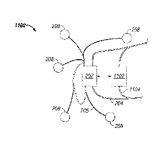
[0058] Referencing Fig. 3, a system 1100 includes a regional blending facility
202 is
positioned in proximity to a hydrocarbon field having a number of wellsites
208. The
arrangement of the regional blending facility 202 and the wellsites 208 is a
non-limiting
example. The system 1100 includes the regional blending facility 202 co-
located with a
supply facility 1102. In some embodiments, the supply facility 1102 supplies
one or
more bulk material. The supply facility 1102 in the example system 1100 has an
independent external access 1104, such as a road, rail line, and/or canal,
although in
certain embodiments the regional blending facility 202 and the supply facility
1102 may
share the same external access 1104, 204. The system 1100 depicts off-loading
access
206 logistically coupling the regional blending facility 202 with the
wellsites 208, although
17
CA 02866257 2014-09-03
WO 2013/134624
PCT/US2013/029833
the system 1100 may additionally or alternatively include fluid conduits (not
shown) or
other connections between the regional blending facility 202 and the wellsites
208. The
presence of the off-loading access 206 or other connections may be permanent,
temporary, intermittent, and/or provided at the time they will be utilized.
[0059] Referencing to Fig. 4, an example facility 202 is depicted
schematically. The
example facility 302 includes bulk receiving facilities 302 that receive and
store a
number of particle types. In one example, the bulk receiving facilities 302
receive bulk
product from a delivering transport at the loading access 204, and deliver the
bulk
product to bulk storage vessels 304, 306, 308, 310. The example facility 202
includes
the bulk receiving facilities 302 storing each of a distinct one of a number
of particles
size modalities into a corresponding vessel 304, 306, 308, 310. Distinct
particle size
modalities, as utilized herein, include particles having a distinct size
value, which may be
an average particle size, a particle size range, and/or a particle size
maximum and/or
minimum. Optionally, valves 340 are provided to control the flow of materials
from the
bulk receiving facilities 302 to one or more of the bulk storage vessels 304,
306, 308,
310.
[0060] In certain embodiments, the bulk receiving facilities 302 receive and
deliver
chemical or fluid additives to various storage areas of the facility 202. The
bulk receiving
facilities 302 may be a single device, a number of devices, and/or a number of
distributed devices around the facility 202.
[0061] The bulk receiving facility 302 may further include a mobile receiver
that is
capable of being positioned under a bulk material carrier (not shown) that is
positioned
on the loading access 204. For example, a truck or rail car carrying particles
may stop
on the loading access 204 in proximity to the bulk receiving facility 302, and
the bulk
receiving facility 302 includes a receiving arm or funnel that can be rolled
out, slid out,
swiveled out, or otherwise positioned under the bulk material carrier. Any
type of bulk
material and receiving device that is positionable under the bulk material
carrier is
contemplated herein.
[0062] In some embodiments, the bulk receiving facility 302 may further
include a below
grade receiver that allows a bulk material carrier to be positioned
thereabove. In one
example, the loading access 204 includes a road having a hatch, covered hole,
grate, or
any other device allowing bulk material released from the bulk material
carrier to pass
18
CA 02866257 2014-09-03
WO 2013/134624
PCT/US2013/029833
therethrough and be received by the bulk receiving facility 302. The loading
access 204,
in certain embodiments, includes a raised portion to facilitate the bulk
receiving facility
302 having a receiver below the grade of the loading access 204.
[0063] In certain embodiments, the bulk receiving facility 302 may include a
pneumatic
deliver system for pneumatically receiving bulk material. The illustrated
facility 202
includes a pump 320 and pneumatic lines 324 structured in a single system
connecting
the bulk receiving facility 302 and the bulk storage vessels 304, 306, 308,
310. The
configuration of the pneumatic delivery system may be any system understood in
the art,
including individual units for each vessel, grouped or sub-grouped units, etc.
An
example bulk receiving facility 302 is structured to de-pressurize during
delivery from the
bulk material carrier, and/or the pneumatic delivery system depressurizes the
corresponding bulk storage vessel 304, 306, 308, 310 during delivery from the
bulk
material carrier. The facility 202 may include pneumatic equipment (not shown)
to
pressurize the bulk material carrier.
[0064] In certain embodiments, the bulk receiving facility 302 may include a
receiving
area (not shown) to receive and store a bulk material carrier in the entirety.
For
example, an example loading access 204 may include a rail, and the bulk
receiving
facility 302 may include a siding that allows a bulk material carrier to be
received in the
entirety and be utilized directly as one or more of the bulk storage vessels
304, 306, 308,
310 at the facility 202. The bulk receiving facility 302 may be structured to
receive any
type of bulk material carrier in the entirety to be utilized as one or more of
the bulk
storage vessels 304, 306, 308, 310. In certain embodiments, a portion of the
bulk
material carrier may be received directly to act as one or more of the bulk
storage
vessels 304, 306, 308, 310.
[0065] In some embodiments, the facility 202 may include one or more
blending/continuously receiving vessels 312, 314, 316. The
blending/continuously
receiving vessels 312, 314, 316, where present, provide for intermediate
components of
a final product fluid to be prepared in the proper proportions. One or more
particle types
from the bulk storage vessels 304, 306, 308, 310 are delivered in the selected
proportions to the blending/continuously receiving vessels 312, 314, 316. The
bulk
delivery may be pneumatic, for example through the pneumatic lines 324 and/or
through
a separate pneumatic system 324. In certain embodiments, the pneumatic system
may
19
CA 02866257 2014-09-03
WO 2013/134624
PCT/US2013/029833
include a heater 322 that heats the air in the pneumatic lines 324, especially
with respect
to bulk materials that are not sensitive to temperature variations, such as
proppant. The
heater 222 can be particularly beneficial for operations under freezing point,
where the
addition of bulk solids into carrying medium may cause the carrying medium to
freeze.
[0066] In some embodiments, the delivery from the bulk storage vessels 304,
306, 308,
310 to the blending/continuously receiving vessels 312, 314, 316 includes a
mechanical
delivery device. For example, the bulk storage vessels 304, 306, 308, 310 may
include
a portion having a reduced cross-sectional area (e.g. cone bottomed vessels).
A screw
feeder or other mechanical device may also be used to transfer the bulk
material from
the bulk storage vessels 304, 306, 308, 310 to the blending/continuously
receiving
vessels 312, 314, 316. Each of the blending/continuously receiving vessels
312, 314,
316 can be coupleable to one or more of the bulk storage vessels 304, 306,
308, 310,
for example by various valves (not shown). Conversely, each of the bulk
storage
vessels 304, 306, 308, 310 can be coupled to one or more of the
blending/continuously
receiving vessels 312, 314, 316, for example by various valves (not shown).
[0067] Dependent upon the types of treatment fluids produced, one or more of
the
blending/continuously receiving vessels 312, 314, 316 may be dedicated to or
limited to
delivery from one or more of the bulk storage vessels 304, 306, 308, 310. In
one non-
limiting example, a first blending/continuously receiving vessel 312 receives
particles
from the first bulk storage vessel 304, a second blending/continuously
receiving vessel
314 receive particles from the second bulk storage vessel 306, and a third
blending/continuously receiving vessel 316 selectively receives particles from
the third
and/or fourth bulk storage vessels 308, 310. In Fig. 4, the number of bulk
storage
vessels 304, 306, 308, 310 and blending/continuously receiving vessels 312,
314, 316
depicted is illustrative and non-limiting. The example arrangements described
and
depicted are provided as illustrations to depict the flexibility of the
facility 202, but any
arrangement of bulk storage vessels 304, 306, 308, 310 and
blending/continuously
receiving vessels 312, 314, 316 is contemplated herein.
[0068] In some embodiments, the facility 202 may further include a fluid
vessel 330 and
fluid pumps 332. Optionally, the fluid vessel 330 is connected with one or
more fluid
additive tanks 350. The fluid additives from the fluid additive tanks can be
mixed in the
fluid vessel 330 via, for example, a blending device 355. The fluid vessel 330
and fluid
CA 02866257 2014-09-03
WO 2013/134624
PCT/US2013/029833
pumps 332 may contain any type of carrying medium, chemical(s), and/or
additive(s) for
a given treatment fluid. FIG. 4 shows only a single fluid vessel 330 and
circuit that are
coupled to various blending/continuously receiving vessels 312, 314, 316 and a
mixing
device 326 (see below), but it should be understood that any number of fluid
vessels 330
and circuits may be present. Fluid additions to various vessels and streams in
the
facility 202 may be provided as desired and depending upon the fluid
formulation of the
product fluid.
[0069] In some embodiments, the facility 202 may further include a mixing
device 326
that receives material from one or more of the blending/continuously receiving
vessels
312, 314, 316 and provides a mixed product fluid to a product storage vessel
328. The
mixing device 326 may be any mixing device understood in the art that is
compatible
with the components of the treating fluid and that provides sufficient mixing.
Example
and non-limiting mixing devices 326 include a feed screw and a feed screw
having
mixing feature that provides additional fluid motion beyond axial fluid motion
along the
feed screw. An example feed screw with a mixing feature may include a tab, a
slot,
and/or a hole in one or more threads of the feed screw. Other example and non-
limiting
mixing devices 326 include a drum mixer, a ribbon blender, a planetary mixer,
a pug mill,
a blender, a controlled solids ratio blender (e.g. a POD blender), and/or a
colloidal
mixer. Another example mixing device 326 is a twin shaft compulsory mixer.
[0070] The mixer 326, as well as related controls and/or connected hardware to
the
mixer 326, provides in certain embodiments for receiving batched products
according to
a mixing schedule. The mixing schedule may include a schedule in time,
spatial, and/or
sequential mixing descriptions. For
example, and without limitation, the product
provided from each of the blending/continuously receiving vessels 312, 314,
316 and/or
fluid vessel 330 may be varied over time, the product provided from each of
the
blending/continuously receiving vessels 312, 314, 316 and/or fluid vessel 330
may be
provided to the mixing device 326 at distinct spatial positions (e.g. as shown
in Fig. 4),
and/or the product provided from each of the blending/continuously receiving
vessels
312, 314, 316 and/or the fluid vessel 330 may be provided according to a
desired
sequence.
[0071] In certain embodiments, the mixing device 326 and/or associated
equipment
conditions a powder (e.g. with an air pad, vibrator, heater, cooler, etc.)
received at the
21
CA 02866257 2014-09-03
WO 2013/134624
PCT/US2013/029833
mixing device 326. In certain embodiments, the mixing device 326 and/or
associated
equipment provides for a component dispersal. An example component dispersal
includes pre-blending some or all of the component into one of the
blending/continuously
receiving vessels 312, 314, 316 (e.g. to provide hydration time), pre-blending
with an
educator system, utilizing a paddle blender, injection through a pump or
orifice, and/or
injection into a centrifugal pump eye. In certain embodiments, the mixing
device 326
and/or associated equipment provides for fluid conditioning, for example
providing a
desired fluid shear trajectory (high, low, and/or scheduled), de-lumping,
straining,
colloidal mixing, and/or shaking the fluid. In certain embodiments, the mixing
device 326
and/or associated equipment provides for particle conditioning, for example
providing
sufficient fluid shear to break a larger particle size into a smaller desired
particle size,
and/or providing sufficient fluid shear to break or prevent clumping (e.g.
between silica
and calcium carbonate).
[0072] In certain embodiments, the sequencing of the addition of materials
from the
blending/continuously receiving vessels 312, 314, 316, the spatial positions
of the
addition of materials, and/or the timing of the addition of materials, are
selected to
manage, minimize, or otherwise respond to compatibility issue and/or
efficiency of
mixing. For example, additions may be scheduled to minimize a contact time
between
incompatible components, and/or to add a material that minimizes
incompatibility effects
between two materials before one or both of the materials are added. In
certain
embodiments, the sequencing of the addition of materials from the
blending/continuously
receiving vessels 312, 314, 316, the spatial positions of the addition of
materials, and/or
the timing of the addition of materials, are selected to account for physical
deliverability
characteristics of the components to be mixed. For example, a largest
component may
be added at a slow feed rate to the mixing device 326 at a position sweeping
the entire
device. A non-limiting example includes adding a largest component, adding all
of a
smallest component during the addition of the largest component, adding a
medium
component, and then finishing with the remainder of the largest component. A
still
further non-limiting example includes sequentially adding larger components
and
finishing with the addition of the largest component.
[0073] In certain embodiments, the mixing device 326 delivers the mixed
product to a
storage vessel 328. In certain embodiments, the mixing device 326 delivers the
mixed
product fluid directly to a transportation vehicle (not shown) which then
transports the
22
CA 02866257 2014-09-03
WO 2013/134624
PCT/US2013/029833
mixed product to a wellsite 208. In one example, the product storage vessel
328 is
positioned to gravity feed a transportation vehicle. In some other examples,
the product
storage vessel 328 is positioned direction above the off-loading access 206,
which in
turn feeds a transportation vehicle. In certain embodiments, the product
storage vessel
328 is pressurizable. In certain embodiments, the product storage vessel 328
includes a
circulating pump, agitator, bubble column pump, and/or other agitating or
stirring device.
[0074] Referencing Fig. 5, a system 1200 includes a regional blending facility
202. The
system 1200 further includes a fluid conduit 1202 that fluidly couples a
wellsite location
208 with the regional blending facility 202. The fluid conduit 1202 is capable
to deliver
the mixed treatment fluid to the wellsite 208, and/or capable to deliver
produced fluid
from a wellbore positioned at the wellsite 208 to the regional blending
facility 202. For
example and without limitation, the fluid conduit 1202 includes a size,
material, and
pressure rating capable to perform the operations of delivering mixed
treatment fluid to
the wellsite 208, and/or to deliver produced fluids from the wellsite 208 to
the regional
blending facility 202. The fluid compositions, pressures, temperatures, flow
rates, and
other characteristics of the fluids utilized will vary with the
characteristics of the
formation, job designs, and other considerations that are generally known to
one of skill
in the art contemplating a particular wellsite 208, wellbore, and target
formations. The
flow rates of the fluid flowing to the wellsite 208 may be sufficient to
support an ongoing
real-time operation such as a fracture treatment, and/or the wellsite 208
location may
include storage tanks or other features to allow for the treatment fluid to be
transported
to the wellsite 208 before and/or during the treatment operations.
[0075] The fluids flowing to the wellsite 208 may be acids, energized fluids,
fluids having
particulates, HSCF, fluids based upon produced formation fluids (e.g. a gelled
oil
treatment), or any other type of fluid known in the art. The fluids flowing
from the wellsite
208 back to the regional blending facility 202 may be "sour" fluids, gases,
liquids, and
may further include any of the treatment fluids such as during a flowback
operation after
a treatment. In certain embodiments, the fluid conduit 1202 may include
separated
conduits for the fluid flow in each direction, although the same conduits may
be utilized
for flow in each direction.
[0076] In certain embodiments, the mixed treatment fluid, or any other
treatment fluid
including fluids that do not have particulates but that are generated at the
regional
23
CA 02866257 2014-09-03
WO 2013/134624
PCT/US2013/029833
blending facility 202 or a local storage hub, is provided on a continuous
basis and/or
during real-time during a treatment. Provision of fluid on a continuous basis
includes, in
certain embodiments, the mixer 326 accepting fluid, additives, and/or
particles on a
continuous basis in the appropriate ratios to provide a continuous stream of
treatment
fluid during the treatment operations. In certain embodiments, a continuous
stream of
treatment fluids are provided to the fluid conduit 1202 to the wellsite 208
before
treatment operations, for example to fill a vessel or storage tank. In
continuous
operation, the blending/continuously receiving vessels 312, 314, 316 may be
present or
not, and the storage vessel 328 may be present or not. Provision of fluid on a
real-time
basis includes providing fluid during the treatment operations, where the
provided fluid is
utilized as it is provided or within a short time of being provided. Provision
of fluid on a
real-time basis can include storage tanks utilized in the system, for example
to allow for
variability in the treatment flow rate and/or to allow for the regional
blending facility 202
to continue to be operated in a batch mode during the real-time provision. The
regional
blending facility may be operated in either or both of a continuous basis and
a real-time
basis during a given treatment operation.
[0077] Referencing Fig. 6, a system 1300 includes a production fluid treatment
facility
1302 that receives an amount of production fluid from the wellbore through the
fluid
conduit 1202. The production fluid treatment facility 1302 further performs an
operation
to separate the production fluid, to settle the production fluid, to store the
production
fluid, and/or to transmit the production fluid away from the regional blending
facility 202.
Referencing Fig. 7, a system 1400 includes the production facility 1302
operationally
coupled to, and/or co-located with but positioned in a distinct physical
location from, the
regional blending facility 202.
[0078] Referencing Fig. 8, a system 1500 includes a production fluid treatment
facility
1302 that performs an operation to route at least a portion of the production
fluid to a
second fluid conduit 1508 that fluidly couples a second wellsite 1506 location
with the
regional blending facility 202. The system 1500 includes a second wellbore
positioned
at the second wellsite 1506, and where the production fluid treatment facility
1302 is co-
located with the regional blending facility 202. Although a plurality of
wellsites 208 and
second wellsites 1506 are schematically illustrated in Fig. 8, it should be
noted that any
number of wellsites 208 and/or second wellsites 1506 can be present in system
1500. In
some embodiments, more wellsites 208 than second wellsites 1506 are present in
24
CA 02866257 2014-09-03
WO 2013/134624
PCT/US2013/029833
system 1500; in some embodiments more second wellsites 1506 than wellsites 208
are
present in system 1500; in some embodiments, approximately equal number of
wellsites
208 and second wellsites 1506 are present in system 1500.
[0079] In certain embodiments, the production fluid treatment facility 1302
receives an
amount of production fluid from the wellbore through the fluid conduit 1202,
separates
the production fluid into a first production fluid portion and a second
production fluid
portion, that transmits the first production fluid portion (e.g. to an
external facility 1504),
and routes the second production fluid portion to a second fluid conduit 1508
that fluidly
couples a second wellsite location 1506 with the regional blending facility
202. The
system 1500 further includes a second wellbore positioned at the second
wellsite 1506,
where the production fluid treatment facility 1302 is co-located with the
regional blending
facility 202. An example system 1500 further includes the regional blending
facility 202
further providing a well maintenance treatment fluid to one of the fluid
conduit 1202 and
the second fluid conduit 1508, wherein the well maintenance treatment fluid
includes a
mixed treatment fluid, a matrix treatment fluid, a water control treatment
fluid, a fluid
diversion treatment fluid, a stimulation treatment fluid, a paraffin control
treatment fluid,
an asphaltene control treatment fluid, a gas lift fluid, and/or a particulate
consolidation
treatment fluid. An example system 1500 includes wellsites 208 corresponding
to
production wells, and wellsites 1506 corresponding to injection wells. The
first
production fluid portion may be hydrocarbons or other commercial products of
the
produced fluids, and the second production fluid portion may be remainder
fluids such as
water. The second production fluid portion may be combined with other
injection fluids
before sending to the second fluid conduit 1508.
[0080] Referencing to Fig. 9, an example blending plant 400 is illustrated.
The blending
plant 400 may include a number of bulk storage vessels 402. Example storage of
bulk
materials includes cone bottom vessels that may be readily emptied through the
bottom.
In some instances augers may be used to pull material from the bottom of the
storage
vessel and move it to the mixing area. In some cases, a plant uses tanks that
can be
pressurized and pneumatically convey the material, which allows more flexible
location
of the bulk storage and makes combining storage units more feasible. In some
cases,
an storage system may include equipment provided to pressurize and convey the
product with heated and/or dried air. This allows the product to be raised
above the
freezing point, avoiding the product freezing in the mixing system when water
is added.
CA 02866257 2014-09-03
WO 2013/134624
PCT/US2013/029833
In some cases, the blending plant 400 may include an area where the bulk
delivery
carriers (e.g. rail cars) may be parked after delivering bulk materials to the
plant. In
such an event, the carriers themselves can be used as the storage for the
plant, rather
than having separate storage vessels.
[0081] The blending plant 400 may further include a number of
blending/continuously
receiving vessels 404. Each blending/continuously receiving vessel 404 may be
operationally coupled to a load cell (not shown), so that the
blending/continuously
receiving vessel 404 may provide prescribed amounts of each particle from the
bulk
storage vessels 402. Examples of batch measurement of bulk materials include
accumulative and/or decumulative weigh batching, which involves the use of a
storage
device (or batcher) mounted on load cells where the amount of powder can be
determined by weighing the batcher. Accumulative methods measure the
accumulation
of powder delivered to the batcher. Once the appropriate amount is the
batcher, delivery
is stopped and the powder may be supplied to the mixing system. Decumulative
batching uses a large storage vessel where the movement of powder out of the
vessel is
measured. An example batch measurement system includes a batcher that is
slightly
larger than needed, where the batcher is filled by weight to slightly more
than needed.
Then, powder is extracted and a more precise measurement is made by
decumulation.
[0082] Alternatively or additionally, batch measurement is achieved by direct
control of
the moving product. In certain embodiments, calibrated feeders (such as screw,
belt,
airlock, starwheel, or vibratory feeders) are used. In certain other
embodiments, flow
measuring devices (such as flow meters, mass flow meters, impact particle flow
meters,
etc.) are used.
[0083] A fluid vessel 406 may be provided along the blending/continuously
receiving
vessels 404. The blending/continuously receiving vessels 404 and the fluid
vessel 406
can be loaded on a raised trailer, as illustrated in Fig. 9, which can provide
convenient
loading or passing to a mixer (not shown) positioned underneath the raised
trailer. The
blending/continuously receiving vessels 404 may provide particles to the mixer
through a
screw feeder or other feeding device, as can be understood by people skilled
in the art.
[0084] The blending plant 400 may further include a number of carrying medium
vessels
414. The carrying medium vessels 414 may contain water, brine, as well as any
other
suitable carrying medium. Different carrying medium vessels 414 may contain
the same
26
CA 02866257 2014-09-03
WO 2013/134624
PCT/US2013/029833
type of liquid or distinct types of liquid. The blending plant 400 further
includes a number
of additive vessels 410. The additive vessels 410 may contain chemicals,
gelling
agents, acids, inhibitors, breakers, or any other type of additive to be
combined with the
carrying medium. The skid including the additive vessels 410 may further
include a
batching tub 408. The final mixed product can be stored in finished product
storage 412.
[0085] The units at the example blending plant 400 are shown as skid loaded
and
transportable by standard highway vehicles. In certain embodiments, the entire
bulk
facility 202 can be made from skid loaded and/or transportable units. In
certain
embodiments, a portion or the whole bulk facility 202 are permanently
constructed at a
location.
[0086] The use of a centralized facility 202 and/or a blending plant 400
provides for
enhanced quality assurance and quality control of treatment fluids use at the
wellsite.
The facility 202 ensures that fluids are being generated in a uniform fashion
and with
uniform source materials (e.g. the same water source). Additionally, the
mixing and
material delivery equipment is not being moved or adjusted, and individual
pieces of
equipment are not being changed out ¨ avoiding, for example, part to part
variability that
occurs when different slurry or proppant blenders (such as POD blenders) are
present
on separate locations due to equipment availability. Further, the mixing and
material
delivery equipment at the facility 202 is not constrained to the same mobility
requirements that apply to wellsite mixing and material delivery equipment,
allowing for
higher equipment quality and precision. In certain embodiments, a crew or
crews
working the facility 202 or blending plant 400 may also have a more stable
composition
over time, for example relative to the composition of hydraulic fracturing
crews, so that
variability due to personnel is also minimized.
[0087] Still further, the centralized location of the fluid product provides
one geographic
location for testing one or more fluid features with precision. For example, a
single unit
of expensive testing equipment can thereby test all relevant treatment fluids
for the
region serviced by the facility 202 or blending plant 400. Additionally, any
complex or
time consuming testing procedures can be performed at the facility 202 or
blending plant
400, avoiding travel costs and risks for testing personnel to be available at
individual
wellsite locations. In certain further embodiments, the automation and control
elements
available due to the presence of a controller 1002 (see the description
referencing Fig.
27
CA 02866257 2014-09-03
WO 2013/134624
PCT/US2013/029833
15) provide for improved treatment fluid uniformity, quality assurance (e.g.
feedforward
fluid quality management), and quality control (e.g. feedback fluid quality
management)
over treatment fluids that are individually batched or generated in real-time
for each
treatment at wellsite locations.
[0088] An example centralized facility 202 and/or a blending plant 400
provides an
improved system-wide environmental impact by decoupling the wellsite location
from the
facility 202 location. For example, the facility 202 and/or blending plant 400
can be
provided in an area that is not environmentally sensitive (e.g. an
industrially zoned area),
avoiding areas that are environmentally sensitive. Example and
non-limiting
environmental sensitivities include zoning constraints, noise considerations,
the
presence of endangered species, wetlands, and/or amicability considerations.
Additionally or alternatively, the facility 202 and/or blending plant 400 can
be provided in
an area that enables environmental management, such as carbon capture, fluid
disposal, and/or fluid treatment that is not equivalently available at an
individual wellsite.
[0089] In certain additional or alternative embodiments, the use of a
centralized facility
202 and/or a blending plant 400 provides for an improved environmental impact
of the
treatment fluid generation system. In one example, the facility 202 can be co-
located
with treatment facilities and/or disposal facilities. As an example, carbon
capture
facilities (e.g. a disposal well) may be present to store carbon dioxide
emissions from
various powered equipment at the facility 202. Any chemical or fluid effluents
from the
facility 202 can be treated into neutral products and/or stored in a disposal
facility (e.g. a
separate disposal well, the same disposal well, and/or a separate geological
zone within
the disposal well). Additionally, the facility 202 and related equipment is
not constrained
to be highly mobile, and accordingly enhanced environmental equipment (e.g.
dust
catchers, sound mufflers, etc.) may be present that would be inconvenient or
expensive
to include on wellsite mobile equipment.
[0090] Referencing to Fig. 10, an exemplary system 500 for treating a
formation 524
fluidly coupled to a wellbore 522 via a wellhead 520 is shown. A portion or
the entire
setup of system 500 may be present at wellsite 208, 1506, 804, 804', or 904,
although
people skilled in the art with the benefit of the current disclosure may
devise different
setup from the one illustrated in Fig. 10 and described herein. In this
exemplary system
500, one or more wellsite transportation vehicles 502 may be included. The
system 500
28
CA 02866257 2014-09-03
WO 2013/134624
PCT/US2013/029833
may further include one or more vessels 503 for providing mixed product fluid
to a low
pressure manifold 504. The low pressure manifold 504 may be fluidly coupled to
the
suction side 508 of fracturing pumps 510. The fracturing pumps 510 may include
a high
pressure side 506 fluidly coupled through a high pressure line 518 to a
wellhead 520.
The system 500 may further include a circulation pump 512 such as a
centrifugal pump
on the low pressure side to facilitate the flow of the low pressure fluid from
the low
pressure manifold 504 to the fracturing pumps 510.
[0091] The system 500 may further include one or more check valves 516
positioned
between the low pressure manifold 504 and the vessels on the wellsite
transportation
vehicles 502. Additional or alternative, the system 500 may be a system that
includes a
means for adding a gel pill (e.g. a gel pill fluid source and pressurizing
pump), a system
without a low pressure manifold 504, a system with one or more fracturing
pumps
dedicated to particle free solution delivery (which may be coupled to a high
pressure
manifold), and/or a system with a fluid tank and fluid tank delivery pressure
mechanism
(e.g. sufficient hydraulic pressure from the orientation and/or raising of the
fluid tank,
pressurizing pump for the fluid tank, etc.).
[0092] The wellbore 522 may be cased and/or cemented into the ground.
Alternatively
or additionally, the wellbore 522 may be open or otherwise unfinished or
uncompleted.
The wellbore 522 may be a vertical well or a horizontal well, as shown in Fig.
10. The
formation 524 may be an oil formation, a shale gas formation, a source rock,
or a
formation bearing any other type of hydrocarbon or natural resource that is
interested to
the operator.
[0093] An example procedure that can be implemented by system 500 may include
performing the fracture treatment where no blender is present at the location.
An
example procedure may further include an operation to recirculate a sump of
the positive
displacement pump during the pumping. The operation to recirculate the sump
and/or
suction side of the positive displacement pump includes operating a
recirculating pump
fluidly coupled to the sump/suction side of the fracturing pump.
[0094] Referencing Fig. 11, an example operation 600 includes a pump-ready
fluid 602
that is prepared at a facility 202 and transported to the wellsite via a
transportation
vehicle 502. The pump-ready fluid 602 can then be pumped downhole in operation
614.
Accordingly, in certain embodiments, a fracturing operation is performed
without a
29
CA 02866257 2014-09-03
WO 2013/134624
PCT/US2013/029833
proppant vehicle (sand truck, sand chief, etc.) and/or a blender (e.g. a POD
blender)
present on the location. In certain embodiments, the fracturing operation is
performed
without a continuous mixer provided on the location. In certain embodiments,
the
fracturing operation is performed without a continuous mixer and without pre-
batching
fracturing fluid into tanks provided on the location, including large water
tanks (e.g. 400
BBL tanks). The footprint needed at the wellsite for a fracturing operation
can be
significantly reduced.
[0095] Fig. 12 illustrates a fracturing operation 700 which, in addition to
the embodiment
represented in Fig. 11, further includes one or more water tanks 704. In
certain
embodiments, the water tanks 704 can be used to provide flush and/or
displacement
fluids. Additionally or alternatively, the water tanks 704 can be used to
provide dilution
water to bring a super-concentrated pump-ready fluid 702 down to a designed
particle
content and/or density before the operation 714 to pump the slurry downhole.
The
pump-ready fluid 702 and/or water tanks 704 are provided, in certain
embodiments, with
sufficient inherent pressure (e.g. through elevation, fluid depth, head tanks,
etc.) that a
blender or other pressurizing equipment is not required to feed the pump-ready
fluid 702
and/or water from the water tanks 704 to the fracturing pumps. Moreover, in
certain
embodiments, a fracturing operation is performed without a proppant vehicle
(sand truck,
sand chief, etc.) and/or a blender (e.g. a POD blender) present on the
location. In
certain embodiments, the fracturing operation is performed without a
continuous mixer
provided on the location. Therefore, the footprint needed at the wellsite for
a fracturing
operation can still be significantly reduced.
[0096] An example procedure, which may be performed in the context of any of
the
systems described herein, includes an operation to interpret a treatment
schedule for a
wellsite and an operation to provide a mixed treatment fluid at a regional
blending facility
in response to the treatment schedule. The procedure includes an operation to
move
the mixed treatment fluid through a fluid conduit from the regional blending
facility to the
wellsite, an operation to produce a fluid from a wellbore at the wellsite, and
an operation
to move the produced fluid through the fluid conduit from the wellsite to the
regional
blending facility. In certain further embodiments, a procedure further
includes an
operation to separate the production fluid into a first production fluid
portion and a
second production fluid portion, an operation to transmit the first production
fluid portion
(e.g. to an external distribution system), and an operation to route the
second production
CA 02866257 2014-09-03
WO 2013/134624
PCT/US2013/029833
fluid portion to a second fluid conduit that fluidly couples a second wellsite
location with
the regional blending facility. An example procedure further includes an
operation to
inject the second production fluid portion into a second wellbore positioned
at the second
wellsite. In certain further embodiments, an example procedure includes an
operation to
co-locate the regional blending facility with a supply facility, where the
operation to
provide the mixed treatment fluid further includes an operation to transfer at
least one
amount of particulates from the supply facility to the regional blending
facility. In certain
embodiments, the example procedure further includes an operation to provide
the mixed
treatment fluid by continuously providing the mixed treatment fluid during
treatment
operations at the wellsite, and/or an operation to provide the mixed treatment
fluid by
providing the mixed treatment fluid in real-time during treatment operations
at the
wellsite.
[0097] Fig. 13A illustrates a variation to the treatment fluid preparation and
delivery
system 200 in Fig. 2. Here, a system 800 is provided which includes a number
of
wellsites 804 and one or more facilities 802, 802' positioned among a
plurality of
wellsites 804, 804' in a "hub and spokes" fashion. An example positioning
includes a
center-of-geography position, a central location, a location minimizing a
total trip time
between a plurality of wellsites 804, 804' and their corresponding facility
802, 802' and/or
any position selected in response to one of the described positions. An
example
position selected in response to one of the described positions includes a
position
nominally selected according to a centralization criterion with respect to the
wellsites
804, 804' and repositioned specifically to an available location, a pre-
existing facility or
graded area, minimal social impact, minimal environmental impact, etc. In
certain
embodiments, the facility 802, 802' is selected to be not greater than a
predetermined
distance from each of a plurality wellsites 804, 804' such as 5 miles, 10
miles, 15 miles,
or 20 miles from each of a plurality of wellsites 804, 804'.
[0098] In certain further embodiments, each wellsites 804, 804' is associated
with one or
more facilities 802, 802'. In certain embodiments, a facility 802, 802' is a
fracture fluid
manufacturing facility, for example as illustrated in Figs. 2, 3, and/or 4. In
certain
embodiments, a facility 802, 802' is an area structured to receive a fracture
fluid
manufacturing facility, for example as illustrated in Figs. 2, 3, and/or 4. An
example
system 800 may also include a fracture fluid manufacturing facility that moves
from
31
CA 02866257 2014-09-03
WO 2013/134624
PCT/US2013/029833
facility 802 to facility 802' according to the group of wells at wellsites
804, 804' presently
being treated.
[0099] Fig. 13B illustrates another variation to the treatment fluid
preparation and
delivery system 200 in Fig. 2. Here, a system 850 is provided which includes
regional
blending facility 202 that is functionally connected to one or more local
storage facility
852, 852'. The connection 858, 858' between the regional blending facility 202
and the
local storage facility 852, 852' can be any vehicle or device, including any
type of road
access, rail access, barge or boat access, tracked vehicle access, pipelines,
etc. The
one or more local storage facility is configured to receive the mixed
treatment fluid from
the regional blending facility and temporarily stores the mixed treatment
fluid before
usage.
[00100] The one or
more local storage facilities 852, 852' can be positioned
among a plurality of wellsites 854, 854' in a "hub and spokes" fashion. An
example
positioning includes a center-of-geography position, a central location, a
location
minimizing a total trip time between a plurality of wellsites 854, 854' and
their
corresponding local storage facilities 852, 852' and/or any position selected
in response
to one of the described positions. An example position selected in response to
one of
the described positions includes a position nominally selected according to a
centralization criterion with respect to the wellsites 804, 804' and
repositioned
specifically to an available location, a pre-existing facility or graded area,
minimal social
impact, minimal environmental impact, etc. In certain embodiments, the local
storage
facilities 852, 852' is selected to be not greater than a predetermined
distance from each
of a plurality wellsites 854, 854' such as 5 miles, 10 miles, 15 miles, or 20
miles from
each of a plurality of wellsites 854, 854'.
[00101] The system
850 may further include a fluid conduit that fluidly couples a
wellsite location with the local storage facility 852, 852', where the fluid
conduit is
capable to deliver the mixed treatment fluid to the wellsite 854, 854', and/or
capable to
deliver produced fluid from a wellbore positioned at the wellsite 854, 854' to
the local
storage facility 852, 852'. The system 850 may further include a fluid conduit
that fluidly
couples the regional blending facility 202 with the local storage facility
852, 852', where
the fluid conduit is capable to deliver the mixed treatment fluid from the
regional blending
32
CA 02866257 2014-09-03
WO 2013/134624
PCT/US2013/029833
facility 202 to the local storage facility 852, 852', and/or capable to
deliver produced fluid
from a local storage facility 852, 852' to the regional blending facility 202.
[00102] Fig. 14
illustrates another variation to the treatment fluid preparation and
delivery system 200 in Fig. 2. Here, a system 900 is provided which includes a
number
of wellsites 904 that are positioned on a single operation site (e.g. a
directional drilling
PAD), and one or more treatment fluid preparation and delivery facilities 902
positioned
on the same operation site. The facility 902 provides pump-ready treatment
fluid to the
wellsites 904.
[00103] In certain
embodiments, a method is disclosed for preparing a pump-
ready fluid. An example method includes providing a carrier fluid fraction,
providing an
immiscible substance fraction including a plurality of particles such that a
packed volume
fraction (PVF) of the particles exceeds 64%, and mixing the carrier fluid
fraction and the
immiscible substance fraction into a treatment slurry. In certain embodiments,
the
immiscible substance fraction exceeds 59% by volume of the treatment slurry.
In certain
embodiments, the immiscible substance fraction exceeds 50% by volume of the
treatment slurry. In certain embodiments, the immiscible substance fraction
exceeds
40% by volume of the treatment slurry. The method includes providing the
treatment
slurry to a storage vessel. The storage vessel may be a vessel at a facility
202 or
blending plant 400. In certain embodiments, the method includes positioning
the storage
vessel at a wellsite. In certain embodiments, the storage vessel is not
fluidly coupled (in
fluid communication) to a wellbore at the wellsite. The storage vessel may be
fluidly
coupleable to a wellbore at the wellsite, and/or the storage vessel may be a
vessel that
is transportable to the wellsite, and/or a storage vessel configured to couple
to and
transfer the pump-ready fluid to a transporting device.
[00104] In certain
embodiments, the method includes positioning the storage
vessel at a wellsite, and/or positioning the storage vessel vertically, for
example where
the storage vessel is a vertical silo. An example vertical silo includes a
frame attached
to the silo that deploys the silo from the transport vehicle, and reloads the
silo to the
transport vehicle after the treatment. Another example vertical silo is a
modular and
stackable silo, which may include an external frame for the silo. Another
example
vertical silo is raiseable directly on the transport vehicle, for example as
shown in Fig.
10. Certain examples of vertical silos that can be used in the current
application are
33
= -
81782263
described In US. Patent Application Pub. No. US 2011/0063942, and in PCT
Patent
Application Pub. No. WO 2009/030020 Al.
[00105] in certain embodiments, the method includes fluidly
coupling the storage
vessel to a pump intake, and treating a wellbore with the treatment slurry. In
certain
embodiments, the method further includes providing all of a proppant amount
for the
treating of the wellbore within the treatment slurry. Stated differently, in
certain
embodiments no proppant is added to the treatment slurry after the pump-ready
treatment fluid is prepared. Accordingly, the treating equipment omits, in
certain
embodiments, a proppant delivery vehicle (e.g. sand truck and/or sand Chief)
and/or a
blender (e.g. a POD blender).
[00106] In certain further embodiments, the method includes
performing the
operations of: providing the carrier fluid fraction, providing the immiscible
substance
fraction, and mixing the carrier fluid fraction, at a facility remote from a
wellsite. The
welisite is any one of the wellsites intended to be served by the facility,
and/or Intended
as the treatment target for the treatment slurry. An example facility includes
a powered
device to perform at least one of the providing and mixing operations, and an
example
method further includes capturing a carbon dioxide emission of the powered
device. An
example capturing operation includes capturing the carbon dioxide emission by
Injecting
the carbon dioxide into a disposal well operationally coupled to the facility,
although any
carbon capture operation known In the art Is contemplated herein. In certain
embodiments, the method further Includes capturing and disposing of a
treatment fluid
byproduct at the facility remote from the welisite. The disposing of the
treatment fluid
byproduct includes any treating operation to render the treatment fluid
byproduct
harmless, and/or direct disposal of the treatment fluid byproduct, for example
Into a
disposal well. The disposal well for captured carbon and the disposal well for
the
treatment fluid byproduct may be the same or distinct wells, and the
geological
formations for disposal within the disposal well may be the same or distinct
formations.
[00107] in certain further embodiments, an example method includes
selecting a
location for the facility remote from the welisite by selecting a location
having an
enhanced environmental profile relative to an environmental profile of the
welisite, where
the welisite is an intended treatment target for the treatment slurry. The
determination of
34
CA 2866257 2020-03-10
CA 02866257 2014-09-03
WO 2013/134624
PCT/US2013/029833
an enhanced environmental profile may be made with respect to any
environmental
consideration. Example and non-limiting environmental considerations include
zoning,
regulatory, situational, and/or amicability considerations. Examples include
locating the
facility in an industrial zoned area, locating the facility away from
environmentally
sensitive areas (officially recognized or otherwise), locating the facility
where adequate
disposal is present or can be made available, locating the facility in an area
supported by
nearby property owners or local governments, etc.
[00108] Referring
to Fig. 15, a control unit 1000 can be included in any of the
treatment fluid preparation and delivery system 200, 800, 900, 1100, 1200,
1300, 1400,
1500, 1600 described above. The control
facility 1000 can be structured to
communicate with and/or control any or all aspects of a facility 202, 802,
902. In certain
embodiments, the control unit 1000 can be structured to remotely communicate
with
and/or control any or all aspects of a facility 202, 802, 902, and/or a
blending plant 400.
Remote communication and/or control can accomplished through any means
understood in the art, including at least wireless, wired, fiber optic, or
mixed
communications network, and/or through Internet or web-based access.
[00109] The control
unit 1000 may include a controller 1002 structured to
functionally execute operations to communicate with and/or control the
facility 202, 802,
902. In certain embodiments, the distance of communication exceeds 250 miles,
although any other distance can be contemplated. In certain embodiments, the
controller 1002 forms a portion of a processing subsystem including one or
more
computing devices having memory, processing, and communication hardware. The
controller 1002 may be a single device or a distributed device, and the
functions of the
controller may be performed by hardware or software. The controller 1002 may
be in
communication with any sensors, actuators, i/o devices, and/or other devices
that allow
the controller to perform any described operations.
[00110] In certain
embodiments, the controller 1002 may include one or more
modules structured to functionally execute the operations of the controller.
In certain
embodiments, the controller includes facility feedback module 1004, a
treatment design
module 1006, and a facility control module 1008. An example facility feedback
module
1004 may interpret facility conditions, including temperatures, pressures,
actuator
positions and/or fault conditions, fluid conditions such as fluid density,
viscosity, particle
CA 02866257 2014-09-03
WO 2013/134624
PCT/US2013/029833
volume, etc., and supply indications for various materials at the facility. An
example
treatment design module 1006 may interpret a treatment schedule, a fluid
recipe, and/or
fluid preparation conditions. An example facility control module 1008 may
provide facility
commands in response to the facility conditions and the treatment schedule,
wherein
one or more actuators or display units at the facility are responsive to the
facility
commands. In certain embodiments, the controller 1002 further includes a
facility
maintenance module 1010. An example facility maintenance module 1010 may
provide
a facility supply communication and/or a facility maintenance communication in
response
to the facility conditions and/or the treatment schedule.
[00111] The
description herein including modules emphasizes the structural
independence of the aspects of the controller, and illustrates one grouping of
operations
and responsibilities of the controller. Other groupings that execute similar
overall
operations are understood within the scope of the present application. Modules
may be
implemented in hardware and/or software on computer readable medium, and
modules
may be distributed across various hardware or software components. Moreover,
certain
operations described herein include operations to interpret one or more
parameters.
Interpreting, as utilized herein, includes receiving values by any method
known in the art,
including at least receiving values from a datalink or network communication,
receiving
an electronic signal (e.g. a voltage, frequency, current, or PWM signal)
indicative of the
value, receiving a software parameter indicative of the value, reading the
value from a
memory location on a computer readable medium, receiving the value as a run-
time
parameter by any means known in the art including operator entry, and/or by
receiving a
value by which the interpreted parameter can be calculated, and/or by
referencing a
default value that is interpreted to be the parameter value.
[00112] Referencing
back to Fig. 15, an example controller 1002 forming a portion
of a control unit 1000 is described. The controller 1002 may includes a
facility feedback
module 1004, a treatment design module 1006, and a facility control module
1008. An
example facility feedback module 1004 interprets facility condition(s) 1012.
Example
and non-limiting facility conditions include any temperature at the facility
(e.g. of a fluid,
product, ambient temperature, a temperature of any actuator, etc.), any
pressure at the
facility, a feedback response of any actuator position or state, an amount of
any material
present at the facility, and measured fluid conditions such as fluid density,
viscosity,
particle volume, etc., and/or a fault or diagnostic value of any equipment at
the facility.
36
CA 02866257 2014-09-03
WO 2013/134624
PCT/US2013/029833
[00113] The example
controller 1002 further includes a treatment design module
1006. The example treatment design module 1006 interprets a treatment schedule
1014. An example treatment schedule 1014 includes information relevant to a
production fluid to be produced at the facility. An example treatment schedule
1014 may
include a fluid type, fluid amount, fluid ingredients, and fluid
characteristics, such as
density, viscosity, particle volume, etc. The fluid type may be a quantitative
or qualitative
description. The controller 1002 in certain embodiments accesses stored
information to
determine the formulation of a qualitatively described fluid. In certain
embodiments, the
treatment schedule 1014 includes a number of fluids, a trajectory of fluids
(e.g. a fluid
density or proppant density ramp), and/or a sequence of fluids.
[00114] In certain
embodiments, the treatment schedule 1014 further includes a
fluid recipe 1016. An example and non-limiting fluid recipe 1016 may include a
list of
ingredients to be mixed to provide the pump-ready treatment fluid, the amount
of each
ingredient, a mixing schedule (e.g. a first particle type to be added first,
and a second
particle type to be added second, etc.), a gelling schedule, a breaker
schedule, a desired
fluid density and viscosity, etc. Any fluid formulation information that is
actionable by the
facility is contemplated herein as a potential aspect of the treatment
schedule 1014
and/or fluid recipe 1016. Additionally or alternatively, the treatment
schedule 1014 may
further include fluid preparation conditions 1018. Example and
non-limiting fluid
preparation conditions 1018 include fluid shear rates, hydration times,
hydration
temperatures, etc. In certain embodiments, information may overlap between the
fluid
recipe 1016 and the fluid preparation conditions 1018.
[00115] The example
controller 1002 may further include the facility control
module 1008. The facility control module 1008 provides facility commands 1020
in
response to the facility conditions 1012 and the treatment schedule 1014, the
fluid recipe
1016, and/or the fluid preparation conditions 1018. In certain embodiments,
the facility
commands 1020 are direct commands to actuators of the facility. Additionally
or
alternatively, the facility commands 1020 provide instructions that indirectly
cause
operations at the facility ¨ for example communicated information to a display
device
(computer monitor, printout, etc.). Example facility commands 1020 provide the
actions
that create the fluid according to the treatment schedule 1014, adjust
facility operations
according to the measured fluid conditions such as fluid density, viscosity,
particle
volume, etc., and/or provide the actions that create a fluid acceptably close
to the fluid
37
CA 02866257 2014-09-03
WO 2013/134624
PCT/US2013/029833
according to the treatment schedule 1014, for example substituting products
according
to availability, etc.
[00116] The example
controller 1002 may further include a facility maintenance
module 1010 that provides a facility supply communication 1022 and/or a
facility
maintenance communication 1024 in response to the facility conditions 1012
and/or the
treatment schedule 1014 including the fluid recipe 1016 and/or the fluid
preparation
conditions 1018. An example includes any actuator or sensor fault or
diagnostic
indicator at the facility may be provided by the facility maintenance module
1010, for
example as a facility maintenance communication 1024 that is communicated to
notify a
maintenance operator of the condition. In certain embodiments, a facility
condition 1012
indicating that a fluid constituent is not available in sufficient quantities
or is running low
may be communicated as a facility supply communication 1022. The described
usages
of the facility supply communication 1022 and the facility maintenance
communication
1024 are examples and non-limiting. Without limitation, any indication that an
aspect of
the facility is non-functional, degrading, running low, below a predetermined
threshold
value, and/or of an unknown status may be communicated by the facility
maintenance
module 1010 and/or controller 1002.
[00117] In certain
embodiments, the controller 1002 further includes the treatment
design module 1006 that interprets a treatment schedule 1014 including a fluid
recipe
1016 and fluid preparation conditions 1018, a facility control module 1008
that provides
facility commands 1020 in response to the fluid recipe 1016 and fluid
preparation
conditions 1018, and a production management module 1608 that interprets a
production status 1610 corresponding to one of the wellsite locations and
provides a
facility production communication 1622 in response to the production status
1610. The
subsystem for providing the mixed treatment fluid is responsive to the
facility commands
1020, and the subsystem for processing the production fluid amount is
responsive to the
facility production communication 1622.
[00118] Example and
non-limiting operations of a subsystem for providing the
mixed treatment fluid include providing a fluid for a treatment operation on a
producer or
injector well, and/or providing valve or flow hardware configurations such
that fluid
conduits between one or more wells are positioned to allow flow from the
regional
blending facility toward the well. Additional or example operations include
providing a
38
CA 02866257 2014-09-03
WO 2013/134624
PCT/US2013/029833
stimulation fluid, a wellbore maintenance fluid, a gas lift fluid, and/or any
other fluid that
is injectable into a wellbore.
[00119] Example and
non-limiting operations of a subsystem for processing the
production fluid amount include determining that a producer well is producing
fluid and
providing valve or flow hardware configurations such that fluid conduits
between one or
more wells are positioned to allow flow from the producer well to toward the
regional
blending facility. Additional or example operations include determining the
type of
produced fluid and any fluid additives, treatment operations, or other
operations
indicated according to the type of produced fluid. Further example operations
include
determining that produced fluid includes treatment flowback fluid for disposal
or
bypassing around a production fluid facility, determining a gas cut or water
cut of
produced fluid, and/or reporting information about the produced fluid
(quantities,
composition, volumes, etc.). Information may be reported, without limitation,
to an
external device (e.g. datalink, network, etc.), stored on a computer readable
medium,
and/or displayed on an output device for hard copy storage or manual storage
by an
operator.
[00120] In certain
further embodiments, the controller further includes a producer
management module 1602 that interprets a producer treatment schedule 1612 and
determines producer operations 1614 in response to the producer treatment
schedule
1612. The system further includes a subsystem for providing a producer
treatment fluid
in response to the producer treatment schedule 1612, where the subsystem for
providing
the producer treatment fluid is responsive to the producer operations 1614.
Example
and non-limiting examples of producer operations 1614 include shut-in times
for a
producer well, types and amounts of fluids to provide from a producer
treatment
schedule 1612, and/or operations to perform tests (e.g. a reservoir pressure
test, or a
near-wellbore damage diagnostic test) on a producer well. Example and non-
limiting
producer treatment fluids include a stimulation fluid, a particle securing
treatment fluid
(e.g. resin, fibers, a sand pack fluid, etc.), a corrosion inhibitor fluid, a
well maintenance
fluid, a gas lift fluid, a wettability change fluid, and/or a fluid diversion
or shutoff fluid. In
certain embodiments, the subsystem for providing the producer treatment
includes:
sources for base fluid, viscosifiers, additives, and particulates; equipment
for mixing fluid
constituents to produce the producer treatment fluid; and/or equipment for
providing the
producer treatment fluid to a fluid flow location that is accessible to the
fluid conduit. In
39
CA 02866257 2014-09-03
WO 2013/134624
PCT/US2013/029833
certain embodiments, the subsystem for providing the producer treatment fluid
includes
equipment from the regional blending facility, and may be fully included
within the
regional blending facility, include shared equipment with the regional
blending facility, be
entirely separate from the regional blending facility, and/or be co-located
with the
regional blending facility.
[00121] The
controller may further include an injector management module 1604
that interprets an injector treatment schedule 1618 and determines injector
operations
1620 in response to the injector treatment schedule 1618, where subsystem for
providing an injector treatment fluid in response to the injector treatment
schedule 1618,
and where the subsystem for providing the injector treatment fluid is
responsive to the
injector operations 1620. Example and non-limiting examples of injector
operations
1620 include shut-in times for an injector well, types and amounts of fluids
to provide
from an injector treatment schedule 1618, and/or operations to perform tests
(e.g. a
reservoir pressure test, a near-wellbore damage diagnostic test, or an
injectibility test) on
an injector well. Example and non-limiting injector treatment fluids include a
stimulation
fluid, a particle securing treatment fluid (e.g. resin, fibers, a sand pack
fluid, etc.), a
corrosion inhibitor fluid, a well maintenance fluid, a wettability change
fluid, a fluid
diversion or shutoff fluid, and/or a sweeping or flushing fluid. In certain
embodiments,
the subsystem for providing the injector treatment includes: sources for base
fluid,
viscosifiers, additives, and particulates; equipment for mixing fluid
constituents to
produce the injector treatment fluid; and/or equipment for providing the
injector treatment
fluid to a fluid flow location that is accessible to the (second) fluid
conduit. In certain
embodiments, the subsystem for providing the injector treatment fluid includes
equipment from the regional blending facility, and may be fully included
within the
regional blending facility, include shared equipment with the regional
blending facility, be
entirely separate from the regional blending facility, and/or be co-located
with the
regional blending facility.
[00122] In certain
further embodiments, the system includes each of the wellsites
fluidly coupled to the regional blending facility with at least one fluid
conduit, where each
fluid conduit is capable to deliver the mixed treatment fluid to the wellsite,
produced fluid
from a wellbore positioned at the wellsite to the regional blending facility,
and/or injection
fluid to the wellsite. The system may include the facility production command
1622
being a separation command, where the injection fluid includes a separated
portion of a
CA 02866257 2014-09-03
WO 2013/134624
PCT/US2013/029833
produced fluid. The system may include a supply facility that provides at
least one
particulate material to the bulk receiving facilities, where the supply
facility is co-located
with the regional blending facility, and the controller includes a supply
management
module 1606 that interprets a supply status 1624 and the treatment schedule
1014, a
producer treatment schedule 1612, and/or an injector treatment schedule 1618.
The
supply management module 1606 further provides a facility supply communication
1022
in response to the treatment schedule 1014, the producer treatment schedule
1612,
and/or the injector treatment schedule 1618 ¨ where the supply facility is
responsive to
the facility supply communication. Example and non-limiting supply status 1624
values
include the operability of the supply facility, inventory or supply amount
values, rates of
production and/or available rates of production, particle availability
descriptions,
downtime or maintenance descriptions, and/or cost values.
[00123] In certain
embodiments, a method is disclosed which includes preparing a
pump-ready fracturing fluid, delivering the pump-ready fracturing fluid to a
location
operationally coupled to a wellsite, and pumping the fracturing fluid downhole
to fracture
a subterranean formation. The pump-ready fracturing fluid may be a fluid that
is directly
provideable to a pump for high pressure delivery. The pump-ready fracturing
fluid may
be further conditioned, as additional additives, liquid, etc. may be added to
the pump-
ready fracturing fluid before or during a formation treatment operation. The
method may
further include providing the pump-ready fracturing fluid to a positive
displacement pump
inlet, and pumping the pump-ready fracturing fluid into a wellbore. The method
may
further include combining pump-ready fracturing fluid sources in a manifold,
pressurizing
the pump-ready fracturing fluid, and/or providing shear or residence time
conditions
upstream of the positive displacement pump inlet. In certain embodiments the
method
includes hydrating, shearing, or conditioning the pump-ready fracturing fluid
before the
providing the pump-ready fracturing fluid to the positive displacement pump
inlet. In
certain embodiments, the method includes recirculating a sump side of the
positive
displacement pump during the pumping. In certain embodiments, the method
includes
pumping an alternate fluid pill during the pumping, for example alternating to
the fluid pill
and then back to the pump-ready fracturing fluid.
[00124] In certain
embodiments, a system is disclosed which includes a regional
blending facility that prepares pump-ready treatment fluid for use at a
wellsite. The
regional blending facility may include bulk receiving facilities that receive
and store a
41
CA 02866257 2014-09-03
WO 2013/134624
PCT/US2013/029833
number of particle types, each of the number of particle types having a
distinct size
modality. The facility may include a blending/continuously receiving vessel
and a bulk
moving device to transfer particle types between the bulk receiving facilities
and the
blending/continuously receiving vessel. The facility may further include a
mixer that
receives batched material from the blending/continuously receiving vessel and
provides
a mixed product fluid, a product storage that stores the mixed product, and a
transportation device that delivers the prepared fluid to a wellsite for
usage.
[00125] In certain
embodiments, the bulk receiving facilities may include a mobile
receiver that positions under a bulk material carrier, a below grade receiver
that allows a
bulk material carrier to be positioned thereabove, a depressurized receiver
that
pneumatically receives bulk material, and/or a receiving area that receives
and stores a
bulk material carrier in the entirety. In certain embodiments, the bulk moving
device may
include a pneumatic system utilizing heated air and/or a mechanical bulk
transfer device.
In certain embodiments, the blending/continuously receiving vessel includes a
portion of
a batching device, wherein the batching device includes an accumulative batch
measurement device, a decumulative batch measurement device, and/or an
intermediary vessel sized to be larger than a batch size, where the batching
device
includes structures for accumulating an amount larger than the batch size in
the
intermediary vessel, and decumulating the batch size from the intermediary
vessel. An
example batching device may additionally or alternatively include a number of
batch
vessels each receiving one of a plurality of distinct product modalities, or
each receiving
a distinct mix of product modalities.
[00126] An example
mixing device includes a feed screw operationally coupling
the blending/continuously receiving vessel to the product storage, a feed
screw
operationally coupling the blending/continuously receiving vessel to the
product storage,
the feed screw including a mixing feature, and/or a feed screw operationally
coupling the
blending/continuously receiving vessel to the product storage. The feed screw
may
include a mixing feature, wherein the mixing feature comprises at least one of
a tab, a
slot, and a hole. Additionally or alternatively, the mixing device may include
a drum
mixer, a ribbon blender, a twin shaft compulsory mixer, a planetary mixer, a
pug mill, a
blender (e.g. a POD blender), and/or a colloidal mixer.
42
CA 02866257 2014-09-03
WO 2013/134624
PCT/US2013/029833
[00127] In certain
embodiments, the product storage may include tanks having a
portion with a reduced cross-sectional area, a vessel positioned to gravity
feed the
wellsite transportation device, a vessel having a head tank, a pressurizable
storage
vessel, and/or an agitation device. In certain embodiments, the wellsite
transportation
device is sized in response to a density of the mixed treatment fluid. An
example
wellsite transportation device may be deployable as a vertical silo, a trailer
having an
elevated portion, a plurality of trailers having coupled portions, and/or an
unfolding
trailer.
[00128] In certain
embodiments, a method is disclosed for preparing a pump-
ready fluid. An example method includes providing a carrier fluid fraction,
providing an
immiscible substance fraction including a plurality of particles such that a
packed volume
fraction (PVF) of the particles exceeds 64%, mixing the carrier fluid fraction
and the
immiscible substance fraction into a treatment slurry, and providing the
treatment slurry
to a storage vessel. The immiscible substance fraction exceeds 59% by volume
of the
treatment slurry, or 50% by volume of the treatment slurry, or 40% by volume
of the
treatment slurry. The method may further include positioning the storage
vessel at a
wellsite, and/or positioning the storage vessel vertically, for example where
the storage
vessel is a vertical silo. The method may further include fluidly coupling the
storage
vessel to a pump intake, and treating a wellbore with the treatment slurry. In
certain
embodiments, the method further includes providing all of a proppant amount
for the
treating of the wellbore within the treatment slurry. The example method in
certain
embodiments includes transferring the treatment slurry to a transportation
device.
[00129] In certain
further embodiments, the method includes performing the
operations of: providing the carrier fluid fraction, providing the immiscible
substance
fraction, and mixing the carrier fluid fraction, at a facility remote from a
wellsite. The
facility includes a powered device to perform at least one of the providing
and mixing
operations, and the example method further includes capturing a carbon dioxide
emission of the powered device. An example capturing operation includes
capturing the
carbon dioxide emission by injecting the carbon dioxide into a disposal well
operationally
coupled to the facility. In certain embodiments, the method further includes
capturing
and disposing of a treatment fluid byproduct at the facility remote from the
wellsite. In
certain further embodiments, the method includes selecting a location for the
facility
remote from the wellsite by selecting a location having an enhanced
environmental
43
CA 02866257 2014-09-03
WO 2013/134624
PCT/US2013/029833
profile relative to an environmental profile of the wellsite, where the
wellsite is an
intended treatment target for the treatment slurry. In certain further
embodiments, the
method includes selecting a location for the facility remote from the wellsite
by selecting
a location having a reduced social impact profile relative to a social impact
profile of the
wellsite, where the wellsite is an intended treatment target for the treatment
slurry.
[00130] While the
disclosure has provided specific and detailed descriptions to
various embodiments, the same is to be considered as illustrative and not
restrictive in
character. Only certain example embodiments have been shown and described.
Those
skilled in the art will appreciate that many modifications are possible in the
example
embodiments without materially departing from the disclosure. Accordingly, all
such
modifications are intended to be included within the scope of this disclosure
as defined
in the following claims.
[00131] In reading
the claims, it is intended that when words such as "a," "an," "at
least one," or "at least one portion" are used there is no intention to limit
the claim to only
one item unless specifically stated to the contrary in the claim. When the
language "at
least a portion" and/or "a portion" is used the item can include a portion
and/or the entire
item unless specifically stated to the contrary. In the claims, means-plus-
function
clauses are intended to cover the structures described herein as performing
the recited
function and not only structural equivalents, but also equivalent structures.
For example,
although a nail and a screw may not be structural equivalents in that a nail
employs a
cylindrical surface to secure wooden parts together, whereas a screw employs a
helical
surface, in the environment of fastening wooden parts, a nail and a screw may
be
equivalent structures. It is the express intention of the applicant not to
invoke 35 U.S.C.
112, paragraph 6 for any limitations of any of the claims herein, except for
those in
which the claim expressly uses the words 'means for' together with an
associated
function.
44