Note: Descriptions are shown in the official language in which they were submitted.
CA 02866337 2014-09-04
WO 2013/144872 PCT/1B2013/052449
HIGH SOLIDS FLUX CIRCULATING CARBONATION REACTOR
FIELD OF THE INVENTION
[0001] The invention relates to a method for capturing carbon dioxide CO2 by a
carbonization reaction wherein recirculation of cooled MeCO3 rich solid
streams is included.
Also, the present invention relates to a system comprising a reactor for
capturing carbon
dioxide CO2 from a CO2 rich flue gas.
BACKGROUND OF THE INVENTION
[0002] Capturing carbon dioxide CO2 may be performed by a carbonation reaction
in
a circulating fluidized bed (CFB) using solids of metal or mineral oxides. The
metal or
mineral oxide acts as an absorbent of the carbon dioxide CO2, being a solid
sorbent.
[0003] The reaction taking place in the CFB carbonation reactor is an
exothermic
reaction where the rate of reaction is dependent largely on the available
surface of the solid
sorbent. In addition, to satisfy reaction kinetic and equilibrium requirements
of the absorption
process precise control of the temperature profile is required. Therefore,
reactor optimization
must consider the absorption heat release, which is 178 kJ/kmol for calcium
oxide CaO
reacting with CO2, the resulting temperature and implications with regard to
equilibrium
driving force and CO2 concentration profiles.
[0004] In a CFB carbonation reactor for processing low pressure combustion
flue gas,
the fractions of solid materials are very low to avoid the otherwise
considerable pressure drop
and associated fan compression power. Reducing equipment sizes for such
fluidized bed
processes implies increasing fluidization velocities which may also lead to
pneumatic
transport operating regimes. The resulting low fractions of solid material are
characterized by
low overall heat transfer coefficients which ultimately depend on the
fluidization gas
properties. Consequently, the presently known systems for capturing carbon
dioxide CO2 in
CFB carbonation reactor require relatively large heat transfer surfaces which
must be applied
internally to remove heat from the reacting system and avoid a temperature
increase of the
solids sorbent to the point where the equilibrium driving force disappears and
the reaction no
longer occurs.
[0005] Previously known reactors remove heat from the CFB carbonation reactor
according to the rate of adsorption via heat transfer area installed in the
reactor. These CFB
carbonation reactors include internal cooling arrangements which are placed at
specified,
predetermined locations. A consequence of this is that any fluctuation in
process operating
1
CA 02866337 2014-09-04
WO 2013/144872 PCT/1B2013/052449
conditions requires adjustment in the cooling system. Such unpredictable
fluctuations are
disadvantageous when processes utilizing the CFB carbonation reactor waste
heat are forced
to absorb fluctuations due to poor CFB carbonation reactor control.
Consequently, there is a
demand to improve the heat transfer characteristics of the system, and to
optimize the method
by which heat transfer occurs to ultimately reduce heat transfer surface area
and plant cost.
[0006] Moreover, a careful control of the reactor temperature is of importance
for
avoiding regions having low temperature and a slow reaction rate, or high
temperatures and
poor equilibrium driving forces. In general, poor reactor design would lead to
larger reactor
dimensions than otherwise required for obtaining the same carbon dioxide CO2
capture rate.
[0007] For example, considering calcium oxide CaO as sorbent, and a
concentration
of carbon dioxide CO2 in the carbon dioxide CO2 rich flue gas forwarded to the
CFB
carbonation reactor of 12% by volume, 90% of the carbon dioxide CO2 may be
captured
corresponding to an equilibrium carbon dioxide CO2 partial pressure at 650 C.
However, if
the corresponding equilibrium carbon dioxide CO2 partial pressure at 700 C is
considered,
for the same flue gas, a maximum of only ¨70% capture is possible.
SUMMARY OF THE INVENTION
[0008] By the present invention some of the drawbacks and deficiencies of the
prior
art reactors for capturing carbon dioxide CO2 as well as for the system for
carbonation are
overcome. The invention provides a method and a system for capturing carbon
dioxide CO2
from carbon dioxide CO2 rich flue gas wherein the heat transfer area and the
temperature
profile may be controlled and adjusted in a flexible way.
[0009] An embodiment of the invention is a method for capturing carbon dioxide
CO2
by carbonation in a circulating fluidized bed (CFB) carbonation reactor
provided. The
method comprises the steps of:
[0010] -forwarding a metal oxide Me0 rich solids stream to the lower part of a
circulating fluidized bed (CFB) carbonation reactor;
[0011] -forwarding carbon dioxide CO2 rich gas stream to said reactor;
[0012] -capturing of carbon dioxide CO2 by reacting the carbon dioxide CO2
present
in the carbon dioxide CO2 rich gas system with metal oxide Me0, forming metal
carbonate
MeCO3;
[0013] -separating the metal carbonate MeCO3 from flue gas in a separating
unit;
[0014] -collecting a metal carbonate MeCO3 rich solids stream from the
separating
unit
2
CA 02866337 2014-09-04
WO 2013/144872 PCT/1B2013/052449
[0015] -subsequent division and cooling of said metal carbonate MeCO3 rich
solids
stream into two or more cooled solid streams forming two or more portions
[0016] -adjusting the temperature of said CFB carbonation reactor by addition
of one
or more cooled portions of said metal carbonate MeCO3 rich solids streams to
said CFB
carbonation reactor at various possible locations to optimize the temperature
profile for CO2
capture purposes.
[0017] In one embodiment, the metal oxide Me0 rich solid stream is forwarded
to the
lower part of the circulating fluidized bed (CFB) carbonation reactor.
[0018] According to one embodiment of the method, the temperature is adjusted
by
cooling and recirculating a first portion of MeCO3 rich solids stream to the
CFB carbonation
reactor. Preferably the first portion is recirculated to an inlet in the lower
part of the CFB
carbonation reactor.
[0019] An advantage provided by this embodiment is that heat generated from
the
capture of CO2 in the carbonation reactor is removed externally from the
reactor while
obtaining a very stabile (close to constant) temperature profile by
circulating a large quantity
of the MeCO3 rich sorbent stream dampening the temperature increase in the CFB
riser. The
external removal of heat is more efficient and cost effective. Heat is removed
externally at a
temperature level which is typically between 10 and 50 C below the average
reactor
temperature. Circulating less solids will allow the temperature profile
gradient to increase
(worsening the equilibrium driving force but requiring less fan power) while,
circulation of
more solids will moderate or flatten the profile but will require increased
specific fan powers.
The chosen optimum operating temperature and circulation rate must be
considered on a case
by case basis to maximize value.
[0020] An additional embodiment of the method is wherein the temperature is
adjusted by cooling and recirculating a second (third or fourth ...) portion
(smaller quantities
at lower temperatures, 50 C to 200 C below the average reactor temperature),
of solid
MeCO3 rich solids to an intermediate region(s) or location(s) along the height
profile of the
reactor to control the temperature increase in the riser resulting from the
exothermic
absorption reaction. Further, in this embodiment heat from the capture of CO2
in the
carbonation reactor is removed externally and a uniform profile is obtained
while reducing
the total required solids circulation rate. Increasing the temperature
difference between the
cooled circulated solids stream and the average reactor temperature lower the
quality of heat
removed from the process but allows efficient external heat removal in a cost
effective
3
CA 02866337 2014-09-04
WO 2013/144872 PCT/1B2013/052449
manner without significantly increasing flue gas fan power consumption by
circulating less
solids.
[0021] In both cases the reactor temperature is adjusted by removing heat from
a
circulated MeCO3 rich solids stream. The circulated MeCO3 rich solids stream
may be cooled
in any device located downstream the CFB carbonation reactor, one such
possibility is to cool
the solids in a fluidized bed heat exchanger located down stream the solids
separation device.
[0022] Further, the temperature of the portion of MeCO3 rich solids which is
added to
the lower part of the reactor may be as high as 10 C below the average
reactor temperature.
Portions of MeCO3 added to locations further up along the height profile of
the reactor may
be cooled to more than 200 C below the average reactor temperature, via the
fluidized bed
heat exchanger. These added portions may be added to lower the local reactor
temperature
through solids addition and mixing.
[0023] According to other aspects illustrated herein an embodiment of the
invention is
a system for capturing carbon dioxide from a carbon dioxide CO2 rich flue gas
stream.
[0024] The system comprises:
a circulating fluidized bed (CFB) carbonation reactor for capturing the carbon
dioxide
CO2 present in the flue gas by a carbonation reaction;
a pipe forwarding a metal oxide Me0 rich stream to the CFB carbonation
reactor;
a pipe forwarding the carbon dioxide CO2 rich flue gas stream to the reactor;
a separation device downstream the circulating fluidized bed (CFB) carbonation
reactor separating the MeCO3 rich stream from the flue gas;
a split device for dividing the MeCO3 rich streams in two or more portions
downstream the separating unit;
a fluidized bed heat exchanger for heat exchange the MeCO3 rich stream before
entering the CFB carbonation reactor;
a pipe for recirculating a first portion of the cooled MeCO3 rich stream to
the CFB
carbonation reactor; and
optionally, a pipe for bypassing a portion of the MeCO3 rich stream to the
lower
section of the CFB carbonation reactor.
[0025] The riser of the CFB carbonaction reactor, thus the arrangement which
transports the solid material to the elevated solids separation device, which
may utilize
internal components, such as static mixing devices or distributors, to improve
the radial
distribution of solids over the cross section of the reactor having an added
effect of increasing
the reactor solids concentration and the resulting solids hold-up.
4
CA 02866337 2014-09-04
WO 2013/144872 PCT/1B2013/052449
[0026] Control of the temperature profile in the CFB carbonation reactor is
achieved
by re-circulating streams of solid materials. These re-circulated streams have
the effect to
dampen the increase of temperature which occurs due to heat evolution taking
place in the
CFB carbonation reactor. In this case, typically all the streams of solid
materials forwarded
from the separating unit are forwarded over some type of heat exchanger before
being
returned to the CFB carbonation reactor.
[0027] In the case the heat exchange is effected by way of a fluidized bed
heat
exchanger fluctuations in process conditions may be compensated via
modifications to the
fluidization conditions, in turn influencing the heat transfer coefficient
allowing the
temperature of the cooling side to remain constant (effectively changing heat
flow or duty).
[0028] Optionally, also another heat exchanger, typically a feed effluent heat
exchanger, for transferring heat from the hot Me0 rich stream to the cold
MeCO3 rich steam
can be used to reduce total process heating and cooling requirements. This
heat exchanger
may also be a fluidized bed heat exchanger.
[0029] Depending on circulation rates, internal (over the solids separation
device and
the carbonation reactor riser) and external (between the solids separation
device down stream
the carbonation reactor and an external system which converts the MeCO3 to
Me0) the
temperature of the solid material in the stream exiting the respective heat
exchangers must be
selected to off-set the heat of reaction before being circulated back to the
carbonation reactor.
In addition, the locations where the solids are introduced must be selected to
ensure a suitable
temperature profile over the height of the reactor.
[0030] Further objects and features of the present invention will be apparent
from the
following detailed description and claims.
BRIEF DESCRIPTION OF THE DRAWINGS
[0031] The present invention is described in more detail below with reference
to the
appended drawings:
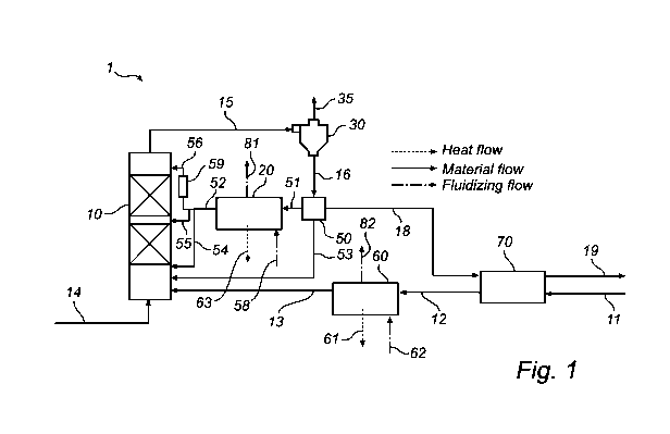
[0032] Figure 1 is a schematic view of a system for carbonization via carbon
dioxide
CO2 rich flue gas and with cooling system connected thereto.
DETAILED DESCRIPTION OF THE INVENTION
The carbonation reaction, thus the reaction between the CO2 in the flue gas
and the
sorbent material, for example selected from a metal oxide (Me0) forming MeCO3
according
to the following reaction equation:
CA 02866337 2014-09-04
WO 2013/144872 PCT/1B2013/052449
Me0 + CO2 -> MeCO3 + Heat
[0033] The reaction is an exothermic reaction which proceeds at a temperature
depended on the metal oxide used. Controlling the temperature is important to
ensure an
efficient reaction system which balances kinetic and equilibrium requirements.
The capturing
of carbon dioxide CO2 may occur with different metal oxides Me0 forming metal
carbonates,
for example limestone. The metal oxides may also be part of a synthetic solid
particle. The
metal oxides used for the invention may be selected from calcium oxide CaO,
magnesium
oxide MgO, aluminium oxide A1203, zink oxide ZnO, and calcium magnesium oxide
CaMg0
forming calcium carbonate (CaCO3), for example in form of calcite or
aragonite; magnesium
carbonate (MgCO3), for example in form of magnesite, alumina carbonate
(Al2(CO3)3); zinc
carbonate (ZnCO3) or in form of calcium magnesium carbonate, such as dolomite
(CaMg(CO3)2), respectively. The list of metal oxides is not exhaustive and the
form in which
the oxides are present on the solids particles is not limited.
[0034] The carbonation reaction, thus the reaction between the CO2 in the flue
gas and
the metal oxide (Me0) is an exothermic reaction which proceeds at a
temperature of,
typically, between 600 C and 850 C, preferably about 650 C, when the metal
oxide is CaO.
The carbonization is an exothermic reaction, thus heat is generated and shall
be removed to
optimize yield, thus to optimize the portion carbon dioxide CO2 captured by
the metal oxide
Me0.
[0035] Also the temperature profile present in the reactor, i.e. the
circulating fluidized
bed carbonation reactor is an important parameter for an efficient reaction.
The energy and
heat must be removed if a uniform temperature profile will be obtained. By
optimizing the
temperature profile present in the carbonation reactor the system can be made
more efficient;
smaller and less expensive.
[0036] Optimization of the reactor also must consider the concentration of
solid
particles, the mass fraction of solids in the reactor and the partial pressure
of carbon dioxide
CO2 over the height of the reactor. The modification of all parameters is
considered with the
ultimate goal to minimize plant costs (capital costs and energy consumption).
[0037] Figure 1 is a schematic representation of the system 1 for capturing
carbon
dioxide CO2 from carbon dioxide rich flue gas by carbonization. The system
comprises a
circulating fluidized bed (CFB) carbonation reactor 10 wherein the bulk of the
carbonization
is taking place.
6
CA 02866337 2014-09-04
WO 2013/144872 PCT/1B2013/052449
[0038] In the CFB carbonation reactor 10, the reaction between the CO2 present
in the
flue gas and the solid metal oxide Me0 fed to the reactor occurs. The reactor
is a so-called
circulating fluidized bed wherein the solid particles are fluidized together
with the flue gas.
The flue gas is introduced in the bottom of the reactor via the duct 14 and
the metal oxide
Me0 rich solids are forwarded via the pipe 13 to the CFB carbonation reactor
10.
[0039] The temperature profile within the reactor varies depending on the
exothermic
reaction. Due to the reaction taking place heat evolution shall be controlled
and adjusted. In
an optimized system the operating temperature profile should be far enough
below the
corresponding equilibrium temperature (according to the CO2 concentration
profile) so as not
to hinder or slow the overall reaction rate.
[0040] After reaction in CFB carbonation reactor 10, a stream rich in the
metal
carbonate MeCO3 entrained in the flue gas is forwarded from the CFB
carbonation reactor 10
via pipe 15 to a separation device 30. (Remaining CO2 in the flue gas may
undergo residual
reaction in the solids separation device but this is small in comparison to
that occurring in the
CFB carbonation reactor 10. Thus, the temperature of this stream is close to
the outlet
temperature of the reactor and is preferably kept at about 650 C when the
metal carbonate is
calcium carbonate CaCO3.
[0041] The separation device 30 separates CO2 lean flue gas from the stream of
MeCO3 rich solid particles and any non-reacted metal oxide Me0. The separation
device 30
may be external to the CFB carbonation reactor 10 (as shown), for example, a
cyclone but
may also be a device which is partially integrated into the CFB carbonation
reactor 10 acting
to lower particle entrainment. It is also possible to use a combination of
both types of devices
internal and external. The cleaned flue gas is forwarded to a flue gas cooler
via the outlet 35.
The remaining solid, material rich in MeCO3, is forwarded via the pipe 16 from
the
separation device 30. A device 50 splits the stream into several parts, this
may be a type of
solids-loop-seal.
[0042] The solid materials separated in the separation device 30 comprise the
metal
carbonate MeCO3 as the main part, and is herein denoted as a "MeCO3 rich
stream". When
calcium oxide CaO is considered as the metal oxide for capturing carbon dioxde
CO2 the
stream has a temperature of about 650 C, when forwarded from the separation
device 30, via
pipe 16, to a split point 50 wherein the stream is divided into two or more
portions, or streams
(shown by streams 51, 53 and 18).
[0043] A portion of solids from the separation device 30 shall be forwarded to
the
fluidized bed heat exchanger 20. The solids present in this fluidized bed heat
exchanger 20
7
CA 02866337 2014-09-04
WO 2013/144872 PCT/1B2013/052449
are fluidized by a fluidizing gas forwarded into the fluidized bed heat
exchanger 20 via duct
58, and leaving the heat exchanger via duct 81. The fluidized bed heat
exchanger 20 is fed
with fluidizing gas, the fluidizing gas, in duct 58, may be compressed air or
compressed flue
gas or steam. The metal carbonate MeCO3 rich stream may then be split into
multiple
streams, i.e. two or more streams and returned to different locations in the
reactor. The stream
rich in solid MeCO3 entering the heat exchanger 20 has a temperature of about
650 C.
Depending on the solids circulation rate the temperature of the solids stream
exiting the
fluidized bed heat exchanger 20 must be selected to off-set the heat of
reaction before being
circulated back to the reactor. The point where the solids are removed from
the exchanger
may be used to influence the stream temperature and the point where the solids
are
introduced to the reactor shall be selected to ensure a suitable temperature
profile over the
height of the reactor. The CFB carbonation reactor 10 may use internal devices
to improve
the solids distribution and thus heat exchange and temperature profile.
[0044] The fluidized bed heat exchanger 20 may be one unit or may be several
units
operating in parallel at different temperatures. Either the stream 51 cooled
before splitting (as
shown) or the stream 51 is split before cooling. In any case the cooler
streams of solids
forwarded from the fluidized bed heat exchanger 20 are re-circulated to the
CFB carbonation
reactor 10 at a suitable position to improve the temperature profile. Stream
54 enters near the
bottom, stream 55 near the mid section of the riser and stream 56 near the top
of the riser, as
shown
[0045] Another portion of the stream 16 may be bypassed to the CFB carbonation
reactor 10, via pipe 53. The bypass is used to control the temperature of the
lower bed to
avoid considerable inlet temperature drops during plant upsets or start-up.
This portion has
typically a temperature of about 650 C but during start-up may also be
somewhat cooler.
[0046] The first 51 and second 53 streams as described above are re-circulated
to the
carbonation reaction taking place in the CFB carbonation reactor 10. The
position of the
inlets along with the temperature and mass flow of the streams 56, 55 or 54
may be adjusted
to optimize the temperature profile in the reactor.
[0047] Optionally, fluidized bed heat exchanger 20 may be split into parallel
units so
that stream 52 of solids obtained after cooling may by multiple streams
flowing in parallel at
various temperatures, herein shown by the two streams 54, 55, 56. A portion of
the stream of
solids 52 enters the CFB carbonation reactor 10 via the pipe 55. Another
portion of the
stream of the solids 52 enters via the pipe 56. Another portion of the solids
may be
lifted/transported to a higher level in the reactor height profile by a
suitable device 59, for
8
CA 02866337 2014-09-04
WO 2013/144872 PCT/1B2013/052449
example a screw device for solid material or pneumatic transport using
compressed air,
compressed flue gas or steam as transport medium.
[0048] From the split point, split device 50, a portion of the stream 16 of
solid
materials rich in CaCO3 is also to be forwarded via pipe 18. The solid
materials have
preferably a temperature of about 650 C. This third stream is forwarded from
the split point
50 via pipe 18 for further processing in a separate system. The metal
carbonate MeCO3 rich
stream may, for example, be forwarded to a unit for decarbonisation (not
shown) to convert
the metal carbonate MeCO3 into metal oxide and carbon dioxide CO2. This
reaction or
process (MeCO3+ heat -> Me0 + CO2) may also be called calcination.
[0049] The system 1 is integrated together with a system for decarbonisation
of
MeCO3 to Me0, a process also called calcination, thus a system wherein CO2 is
released
from the metal carbonate leaving remaining metal oxide Me0 rich solids. Me0
rich solids are
fed to system 1 via pipe 11 into the CFB carbonation reactor 10.
[0050] Optionally, the Me0 rich stream forwarded from the calcination process
may
be cooled in a feed effluent fluidized bed heat exchanger 70, or in a
fluidized bed cooler 60,
or in a system including both.
[0051] Optionally, also stream 18 may be fed to a feed effluent heat exchanger
70 for
transferring heat from the hot product Me0 to the cold MeCO3 reducing total
process heating
and cooling requirements. Here, the metal carbonate is heated by a counter
current stream of
metal oxide Me0 entering unit 70 via pipe 11. The cold MeCO3 is forwarded via
pipe 19 for
further processing in a separate system (not shown). The cooled Me0 rich
stream 12 is
forwarded to a second heat exchanger which further reduces the temperature
before entering
the CFB carbonation reactor 10 via pipe 13. The metal oxide Me0 rich stream
returning from
the calcination process may be further cooled by fluidized bed heat exchanger
60 in parallel
to unit 20. Optionally stream 12 may be fed directly to unit 20 and cooled
before
redistribution via stream 52 to CFB carbonation reactor 10 (not shown in the
figure).
[0052] The heat exchanger 60 may be a fluidized bed heat exchanger in which
case
fluidizing gas (air flue gas or stream) is fed via duct 62 and exits unit 60
via duct 82. Heat
removed over unit 20 and unit 60 may be used for generating steam the heat
streams are
indicated schematically as stream number 61 and 63.
[0053] While the invention has been described with reference to various
exemplary
embodiments, it will be understood by those skilled in the art that various
changes may be
made and equivalents may be substituted for elements thereof without departing
from the
scope of the invention. In addition, many modifications may be made to adapt a
particular
9
CA 02866337 2014-09-04
WO 2013/144872 PCT/1B2013/052449
situation or material to the teachings of the invention without departing from
the essential
scope thereof. Therefore, it is intended that the invention not be limited to
the particular
embodiment disclosed as the best mode contemplated for carrying out this
invention, but that
the invention will include all embodiments falling within the scope of the
appended claims.