Note: Descriptions are shown in the official language in which they were submitted.
CA 02866656 2014-10-06
CAM-004
AIRCRAFT STARTER MOTOR ASSEMBLY
Field
[0001] The disclosure generally relates to the art of aircraft
starter motor
assemblies.
Background
[0002] In some propeller driven aircraft, a starter motor assembly is
used
to turn over the piston engine that drives the propeller. The starter motor
assembly is generally constructed to provide a certain torque and to operate
at
a certain RPM in order to successfully start the engine. However, it has been
found for many years that certain starter motor assemblies have suffered from
a relatively short operating life. This has resulted in relatively high
maintenance
costs for such aircraft, unforeseen periods of inoperability due to an
unexpected failure of the starter motor and drive, and the potential to damage
other parts of the aircraft in certain situations. It would be desirable to at
least
partially resolve these problems.
Summary
[0003] In one aspect an aircraft starter motor assembly for starting an
aircraft engine is provided. The assembly includes a DC electric motor, a
planetary gearset, a ring gear clutch, and a starter adapter. The DC electric
motor has a rotor and a stator. A brush electrically connects a power source
to
the rotor. The rotor drives a motor output shaft. The planetary gearset
includes a ring gear, a planet carrier that holds a plurality of planet gears
and a
sun gear. The sun gear is mounted to the motor output shaft. The ring gear
clutch is controllable to be in an engagement state to fix the angular
position of
1
CA 02866656 2014-10-06
CAM-004
the ring gear and a disengagement state to permit the ring gear to freewheel.
The starter adapter including a worm, a worm biasing member, a worm gear, a
wrap spring clutch and an adapter output shaft. The worm is driven by the
planet carrier and drives the worm gear. The worm is movable linearly
between a home position and a torque transfer position and is biased towards
the home position by the worm biasing member. Torque transfer to the worm
gear caused by rotation of the worm in a first worm direction drives the worm
to
the torque transfer position against a biasing force of the worm biasing
member. The worm gear is drivable in a first rotational direction to bring the
wrap spring clutch to a driving state in which the wrap spring clutch is
operatively engaged the wrap spring clutch with the adapter output shaft. The
adapter output shaft is operatively connected to the aircraft engine and is
rotatable by the worm gear for cranking the aircraft engine. The aircraft
starter
motor assembly is operable in a first mode wherein the ring gear clutch is in
the
engagement state and the electric motor drives the rotation of the planet
carrier. The planet carrier rotates the worm in the first worm direction to
transfer torque from the motor to the worm gear, so as to drive the worm gear
in the first rotational direction to bring the wrap spring clutch to the
driving state
so as to cause rotation of the adapter output shaft, so as to crank the
aircraft
engine. Bringing the ring gear clutch to the disengagement state disengages
the motor from the planet carrier, which in turn permits the worm biasing
member to drive the worm towards the home position, which in turn drives
rotation of the worm gear in a second direction that is opposite the first
direction, which in turn brings the wrap spring clutch to a non-driving state
in
which the wrap spring clutch is at least partially disengaged from the adapter
output shaft.
[0004] In another aspect, an aircraft starter motor assembly for
starting
an aircraft engine is provided, and includes a DC electric motor, a starter
adapter, and a motor clutch. The DC electric motor has a rotor and a stator. A
brush electrically connects a power source to the rotor, and wherein the rotor
drives a motor output shaft. The starter adapter includes a worm having at
2
CA 02866656 2014-10-06
CAM-004
least four starts, a worm gear, a wrap spring clutch and an adapter output
shaft.
The worm is driven by the DC electric motor and drives the worm gear. The
worm gear is drivable in a first rotational direction to bring the wrap spring
clutch to a driving state in which the wrap spring clutch is operatively
engaged
with the adapter output shaft. The adapter
output shaft is operatively
connected to the aircraft engine and is rotatable by the worm gear for
cranking
the aircraft engine. The motor clutch is positionable in an engagement state
to
permit torque transfer from the DC electric motor through the starter adapter,
and a disengagement state to prevent torque transfer from the motor through
the starter adapter. The aircraft starter motor assembly is operable in a
first
mode wherein the motor clutch is in the engagement state and the electric
motor drives the rotation of the worm in the first worm direction to transfer
torque from the motor to the worm gear, so as to drive the worm gear in the
first
rotational direction to bring the wrap spring clutch to the driving state so
as to
cause rotation of the adapter output shaft, so as to crank the aircraft
engine.
Movement of the clutch to the disengagement state disengages the motor from
the worm, which in turn permits returning of the wrap spring clutch to a non-
driving state under spring force in the wrap spring clutch, wherein in the non-
driving state the wrap spring clutch is at least partially disengaged from the
adapter output shaft. Returning of the wrap spring clutch to the non-driving
state in turn drives the worm gear in a second direction that is opposite the
first
direction, thereby back-driving the worm.
[0005] In
yet another aspect, an aircraft starter motor assembly for
starting an aircraft engine is provided and includes a DC electric motor, a
motor
clutch, a solenoid, a switch, and first and second power sources that are
independent of one another. The DC electric motor has a rotor and a stator. A
brush electrically connects a power source to the rotor. The rotor drives a
motor output shaft that is connected to the aircraft engine to start the
aircraft
engine. The motor clutch is positionable in an engagement state to permit
torque transfer from the DC electric motor to the engine, and a disengagement
state to prevent torque transfer from the motor to the engine. The solenoid
3
CA 02866656 2014-10-06
,
CAM-004
includes a solenoid coil, a movable member, a first electrical contact and a
second electrical contact. The movable member of the solenoid is movable to
an engagement position in which the first electrical contact is connected to
the
second electrical contact. The switch is positionable in a first position in
which
the first power source is connected to the solenoid coil, and a second
position
in which the first power source is disconnected from the solenoid coil. The
second power source is connected to the first electrical contact and the
second
electrical contact is connected to a power input terminal for the DC electric
motor. Movement of the switch to the first position connects the first power
source to the solenoid coil to drive the movable member from the
disengagement position to the engagement position so as to connect the
second power source to the DC electric motor so as to drive the DC electric
motor, and moves the motor clutch to the engaged position to transmit torque
from the DC electric motor to the engine. Movement of the switch to the
second position disconnects the first power source from the solenoid coil to
drive the movable member from the engagement position to the
disengagement position so as to disconnect the second power source from the
DC electric motor, and moves the motor clutch to the disengaged position.
Brief Description of the Drawings
[0006] The foregoing and other aspects will be more readily
appreciated
having reference to the drawings, wherein:
[0007] Figure 1 is a top view of an aircraft engine and a
starter motor
assembly in accordance with an embodiment of the present invention;
[0008] Figure 2 is a side sectional view of the starter motor assembly
shown in Figure 1 operating in a first mode;
[0009] Figure 2a is a magnified sectional view of a portion of
the starter
motor assembly shown in Figure 2;
4
CA 02866656 2014-10-06
CAM-004
[0010] Figure 2b is a magnified perspective view of a portion of the
starter motor assembly shown in Figure 2;
[0011] Figure 3 is a side sectional view of the starter motor
assembly
shown in Figure 1 operating in a second mode; and
[0012] Figure 4 is a perspective exploded view of a portion of the starter
motor assembly shown in Figure 2;
[0013] Figure 5A is a schematic diagram of an electrical circuit
used as
part of a starter motor assembly of the prior art;
[0014] Figure 5B is a schematic diagram of an electrical circuit
sued as
part of the starter motor assembly shown in Figure 2; and
[0015] Figure 5C shows a solenoid in Figure 5B in an engagement
position.
Detailed Description
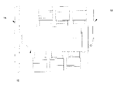
[0016] Figure 1 is a perspective view of an aircraft starter motor
assembly 10 that can be used to start an aircraft engine shown at 12. The
engine 12 may be a multicylinder (e.g. six-cylinder) piston engine that is
used
to drive a propeller, shown at 14. Referring to Figure 2, the starter motor
assembly 10 includes an electric motor 16, a planetary gearset 18, a ring gear
clutch 20 and a starter adapter 22. The electric motor 16 has a rotor 24 and a
stator 26. The electric motor 16 may be called upon to transmit a high amount
of torque and may be a permanent magnet, brushed DC motor. In an
embodiment, the motor 16 makes about 3.3 hp at 24VDC and 2.7 hp at
12VDC. A set of brushes 28 electrically connects a power source (e.g. an on-
board battery 30) to the rotor 24. During operation of the motor 16, the rotor
24
drives a motor output shaft 32.
[0017] The planetary gearset 18 includes a ring gear 34, a planet
carrier
36 that holds a plurality of planet gears 38 and a sun gear 40. The sun gear
40
5
CA 02866656 2014-10-06
CAM-004
is mounted to and driven by the motor output shaft 32. The planet carrier 36
may end in a gearset output shaft 41 with a drive feature 42 thereon.
[0018] The ring gear clutch 20 is controllable via a controller 43
to be in
an engagement state (Figure 2) to fix the angular position of the ring gear 34
and a disengagement state (Figure 3) to permit the ring gear 34 to freewheel.
The planetary gearset 18 has an associated longitudinal axis A.
[0019] The ring gear clutch 20 may include, for example, an
electromagnetic coil assembly 44 including an electromagnetic coil 46 and an
electromagnetic coil housing 48, a first friction plate 50 that has thereon a
first
friction surface 52, and a second friction plate 54 that has thereon a second
friction surface 56. The first friction plate 50 is rotationally fixed, and
may be
stationary both axially and rotationally. In the embodiment shown the first
friction plate 50 forms part of the electromagnetic coil housing 48. The
second
friction plate 54 may be movable (e.g. slidable) axially but may be
rotationally
connected to the ring gear 34 through a friction plate biasing member 58,
fasteners 57a and 57b and a support member 112 as described further below.
[0020] Energization of the electromagnetic coil 46 (by the
controller 43)
causes axial movement of at least one of the first and second friction
surfaces
52 and 56 into engagement with the other of the first and second friction
surfaces 52 and 56 so as to rotationally fix the ring gear 34. In the
particular
embodiment shown, wherein the first friction plate 50 is stationary axially
and
rotationally, energization of the electromagnetic coil 46 causes axial
movement
of the second friction surface 56 into engagement with the first friction
surface
52 so as to rotationally fix the ring gear 34.
[0021] In some embodiments, energization of the electromagnetic coil 46
brings the ring gear clutch 20 to the engagement state, and deenergization of
the electromagnetic coil 46 brings the ring gear clutch 20 to the
disengagement
state. A friction plate biasing member shown at 58 in Figures 2, 2A and 2B
may optionally be provided to urge the second friction plate 54 out of
engagement with the first friction plate 50. The friction plate biasing member
58
6
CA 02866656 2014-10-06
CAM-004
is connected to the support member 112 at first selected points (e.g. three
points 120 degrees apart (Figure 2B) at a selected radius from the axis A
(Figure 2)) by first fasteners, shown at 57a. Additionally, the friction plate
biasing member 58 is connected to the second friction plate 50 at second
selected points (e.g. 120 degrees apart (Figure 2B)) by second fasteners 57b.
The second selected points may be 120 degrees apart at the same radius as
the first selected points such that the second fasteners 57b alternate with
the
first fasteners 57a. The fasteners 57a and 57b could be any suitable type of
fasteners, such as rivets, screws, or any combination thereof. The friction
plate
biasing member 58 biases the friction plate 54 away from the friction plate 50
(i.e. out of engagement with the friction plate 50), so that deenergization of
the
electromagnetic coil 46 brings the ring gear clutch 20 to the disengagement
state. By way of the friction plate biasing member 58, the fasteners 57a and
57b and the support member 112, the friction plate 54 is connected
rotationally
to the ring gear 34.
[0022] The friction plate 54 and the friction plate biasing member 58
are
shown in Figure 2C. The friction plate biasing member 58 is shown with
exaggerated warpage to illustrate the flexing it goes through when the
friction
plate 54 has pulled away from the support member 112 and is engaged with
friction plate 50. As can be seen, the three fasteners 57a (which hold the
friction plate biasing member 58 to the support member 112 (not shown in
Figure 2C) alternate with the three fasteners 57b (which hold the friction
plate
biasing member 58 to the friction plate 54).
[0023] As a result of the illustrated structure, no energy is
required to
hold the ring gear clutch 20 in the disengagement state, which is the state it
will
be in all conditions except when the starter motor assembly 10 is being used
to
start the engine 12. Thus, there is little or no lost energy associated with
the
ring gear clutch 20 when the clutch 20 is not in use. In some embodiments the
friction plate 54 is spaced from the friction plate 50 by about 0.008 to about
0.010 inches. In some embodiments it has been found that about 1.4 Amps
7
CA 02866656 2014-10-06
CAM-004
are needed to bring the plates 50 and 54 together. The close spacing of the
friction plates 50 and 54 is in part responsible for the low amperage needed
to
bring them together and to hold them together. The close spacing is possible
in part because the biasing member 58 is positioned on the side shown at 59 of
the friction plate 54 facing away from the friction plate 50 instead of being
positioned between the friction plates 50 and 54.
[0024] It will be noted that the friction force that holds the ring
gear 34
against rotation is dependent on the normal force (i.e. the force of
engagement
between the surfaces 52 and 56), the friction coefficient between the surfaces
52 and 56 and the area over which they are engaged. By selecting materials
and surface finishes appropriately, a relatively low normal force will be
needed
in order to satisfactorily hold the ring gear 34. Thus, a relatively low
current
and power draw may be associated with this arrangement. It has been found
that, in use, as little as 8 pounds of force have been needed to hold the ring
gear 34 stationary.
[0025] In an alternative embodiment the second plate 54 may simply be
left to float axially when the electromagnetic coil 46 is not energized, so
that it
will find an equilibrium position that is just slightly spaced from the first
plate 50
on its own without the need for a biasing member.
[0026] The gearset 18 may provide any suitable amount of gear
reduction. For example, it may provide a gear reduction of about 3.8:1 (e.g.
3.785:1). Any other suitable gear reduction may be used. It will be noted that
the force needed to hold the ring gear 34 is relatively low in a planetary
gearset, which is advantageous in the assembly 10 since a lower required force
reduces even further the normal force (and therefore the current and power
draw) needed to hold the ring gear 34.
[0027] Referring to Figures 2 and 2a, the starter adapter 22 includes
a
worm 60, a worm biasing member 62 (e.g. a compression spring), a worm gear
64, a wrap spring clutch 66 and an adapter output shaft 68 with a final gear
70
thereon. The worm 60 is mounted on a worm shaft 72 that has an input feature
8
CA 02866656 2014-10-06
CAM-004
74 that mates with the drive feature 42 on the gearset output shaft 41. The
worm 60 is fixed rotationally with the worm shaft 72, but is slidable axially
(linearly) along a worm axis Aw on the worm shaft 72. The worm 60 is biased
by the worm biasing member 62 between a home position (Figure 3) and a
torque transfer position (Figure 2). When the worm 60 is driven rotationally
by
the planet carrier 36, the worm 60 applies a force to cause rotation of the
worm
gear 64. Resistance to rotation by the engine 12 (Figure 1) may be
sufficiently
high such that rotation of the worm 60 does not drive rotation of the worm
gear
64 and instead drives movement of the worm 60 linearly away from the home
position (to the right in the view shown in Figure 2), thereby flexing (i.e.
compressing) the worm biasing member 62. As the worm 60 moves further
from the home position (and towards the torque transfer position) the
resistive
force of the worm biasing member 62 increases. At some point, either the
resistive force of the worm biasing member 62 matches the force urging the
worm 60 to move away from the home position, or the worm 60 reaches the
end of its travel. Regardless of whichever it is, once this occurs, the worm
60
begins to drive rotation of the worm gear 64. At this point the worm 60 may be
said to be in the torque transfer position. Put another way, during operation
of
the assembly 10 to start the engine 12, torque transfer to the worm gear 64
caused by rotation of the worm 60 in a first rotational direction drives the
worm
60 to the torque transfer position against a biasing force of the worm biasing
member 62.
[0028] Referring to Figure 4, the worm 60 may be axially slidable on
the
worm shaft 72 by way of engagement between a Woodruff key 76 that mounts
in a shaft slot 78 in the worm shaft 72 and that engages a worm slot 80 in a
radially inner surface 82 of the worm 60.
[0029] The worm 60 in the embodiment shown may have any suitable
number of starts. For example, it may be a three-start worm. In some
embodiments it may instead be a two-start worm. The worm 60 may be
9
CA 02866656 2014-10-06
CAM-004
backdrivable in some embodiments. In
other embodiments it may be
substantially not back drivable.
[0030] The
wrap spring clutch 66 has a first end 83, a second end 84, a
radially inner surface 85 and a radially outer surface 86. At the first end
83, the
wrap spring clutch 66 includes a hook feature 87 (Figure 4) thereon that
connects the first end 83 to the worm gear 64. Referring to Figure 2, a first
portion 88 of the wrap spring 66 surrounds a worm gear drum 90 which holds
the worm gear 64, and a second portion 91 surrounds the adapter output shaft
68, and more particularly a wrap spring engagement surface 92 on the adapter
output shaft 68.
[0031] The
wrap spring clutch 66 is positionable in a driving state (Figure
2) in which it has coiled inwardly to grip the worm gear drum 90 and the wrap
spring engagement surface 92 so that torque transfer takes place from the
worm gear 64 to the adapter output shaft 68. The wrap spring clutch 66 is also
positionable in a non-driving state (Figure 3) in which it has coiled
outwardly so
that it is at least partially disengaged from the adapter output shaft 68
sufficiently to permit relative movement between the worm gear 64 and the
adapter output shaft 68 without generating excessive heat buildup. It is
preferable, however, for the wrap spring clutch 66 to be fully disengaged from
the output shaft 68, so that there is substantially free movement between the
worm gear 64 and the adapter output shaft 68.
[0032] A
friction ring 98 on a housing 100 (Figure 4) for the starter
adapter 22 is positioned to engage the radially outer surface 86 of the wrap
spring clutch 66 proximate the second end 86 and to hold the second end 86
substantially rotationally stationary when the wrap spring clutch 66 is in the
non-driving state.
[0033]
Holding of the second end 86 of the wrap spring clutch 66 by the
friction ring 98 permits the worm gear 64 to be drivable in a first rotational
direction (shown at D in Figure 4) to cause inward coiling of the wrap spring
clutch 66 so that its inner surface 85 grips the worm gear drum 90 and the
wrap
CA 02866656 2014-10-06
CAM-004
spring engagement surface 92 on the adapter output shaft 68, thereby bringing
the wrap spring clutch 66 to the driving state. At this point the wrap spring
clutch 66 is operatively engaged with the adapter output shaft 68. Continued
rotation of the worm gear 64 transfers torque from the worm gear 64 to the
adapter output shaft 68.
[0034] The wrap spring clutch 66 may be biased towards the non-
driving
state. This permits the wrap spring clutch 66 to return to the non-driving
state
upon a release of the torque that drives the worm gear 64.
[0035] The wrap spring engagement surface 92 may have a plurality of
axially extending grooves 102 thereon that serve to remove debris that may
accumulate between the radially inner surface 85 of the wrap spring clutch 66
and the wrap spring engagement surface 92. Additionally, the edges of the
grooves 94 assist in cleaning debris from the inner surface 96 of the wrap
spring clutch 66. Additionally, the grooves 94 assist in gripping the wrap
spring
clutch 66 during operation of the starter motor assembly 10 in the first mode.
[0036] The adapter output shaft 68 is operatively connected to the
aircraft engine, e.g. via engagement of the final gear 70 on the adapter
output
shaft 68 with an input gear 104 that is connected to the crankshaft (not
shown)
on the engine 12. By way of the wrap spring clutch 66, the adapter output
shaft
68 is rotatable by the worm gear 64 for cranking the aircraft engine 12 in
order
to start the aircraft engine.
[0037] To start the aircraft engine 12, the aircraft starter motor
assembly
10 is operable in a first mode (shown in Figure 2) wherein the ring gear
clutch
20 is brought to the engagement state and the electric motor 16 is energized
and drives the rotation of the planet carrier 36 via the sun gear 40. The
planet
carrier 36 in turn rotates the worm 60 in a first worm direction Dw (Figure 4)
to
transfer torque from the motor 16 to the worm gear 64 so as to drive the worm
gear 64 in the first rotational direction D to bring the wrap spring clutch 66
to
the driving state. This in turn causes rotation of the adapter output shaft
68, so
as to crank the aircraft engine 12.
11
CA 02866656 2014-10-06
CAM-004
[0038] Once the engine 12 has started, power is cut to the motor 16
and
the ring gear clutch 20 is brought to the disengagement state, which
disengages the motor 16 from the planet carrier 36. This, in turn, releases
any
torque from the motor 16 on the worm 60, which permits the worm biasing
member 62 to drive the worm 60 towards the home position. This movement of
the worm 60 towards the home position drives rotation of the worm gear 64 in a
second direction that is opposite the first direction D. This in turn brings
the
wrap spring clutch 66 to the non-driving state.
[0039] To assist the components that make up the adapter 22 in
operating and releasing when desired, a flow of lubricant (i.e. oil) may be
provided into and through the adapter housing 100. Accordingly, the adapter
housing 100 may be sealed as necessary to prevent leakage of oil therefrom.
[0040] Referring to Figure 2, bushings and bearings generally shown
at
108 may be provided between the motor output shaft 32 and the gearset output
shaft 41, between the gearset output shaft 41 and a stationary support 110 for
the electromagnetic coil assembly 48, and between the stationary support 110
and the support member 112 that holds the ring gear 34 and the second friction
plate 54.
[0041] The spacings between components shown in Figures 2 and 3
may be exaggerated for the purpose of clarity. As will be understood these
drawings are not to scale.
[0042] By providing the ring gear clutch 20, it has been found that
the
amount of resistance in the starter motor assembly 10 to unwinding of the wrap
spring clutch 66 is relatively small. By contrast, it has been found that, in
a
prior art configuration that does not include the ring gear clutch 20,
significant
resistance was encountered to the unwinding of the associated wrap spring
clutch. In some instances this resistive torque can be as high as 15 inch
pounds or more at the motor output shaft. When this resistive torque is
combined with the gear reduction that takes place with a planetary gearset,
the
actual resistance to turning of the worm gear in a second direction can be
12
CA 02866656 2014-10-06
CAM-004
significant. In such cases even if the wrap spring clutch is made to disengage
from the adapter output shaft, it does so after significant stresses are
incurred,
thereby reducing the effective life of the motor starter assembly. In some
instances the wrap spring clutch has been found not to disengage completely,
which results in significant heat buildup in the adapter. Thus, the ring gear
clutch 20 has been found to greatly reduce stresses and heat buildup in the
adapter 22 and to extend the effective life of the motor starter assembly 10
as
compared to some prior art assemblies. Furthermore, these advantages are
provided while consuming very little power. It is also noted that, depending
on
the position of the pistons in the aircraft's engine when the engine is
stopped,
there may be some back-rotation of the engine (due to residual pressure in
some of the cylinders). In such cases, a prior art starter motor assembly can
incur significant stresses if the wrap spring clutch has not properly
disengaged
with the adapter output shaft.
[0043] It has been found that the problem with prior art starter motor
assemblies has existed for many years without an effective solution, and has
resulted in many instances of premature failure of components such as the
wrap spring clutch and the worm gear.
[0044] It has been noted above that the worm 60 may be a two-start
worm or a three-start worm. In another embodiment, the worm 60 may be a
four-start worm. In such an embodiment, the ring-gear clutch described above
may be replaced by another clutch that is positionable in an engagement state
to permit torque transfer from the DC electric motor 16 through the starter
adapter 22, and a disengagement state to prevent torque transfer from the
motor 16 through the starter adapter 22.
[0045] In general, it has been found that the use of a worm having
two
starts in some embodiments was advantageous in that it provides a certain
amount of gear reduction, and a commensurate amount of torque increase.
This permitted the use of a smaller starter motor which helped to reduce cost
and weight. It has been found, however, that the two start worm has
significant
13
CA 02866656 2014-10-06
CAM-004
parasitic losses, in the range of 60%, which effectively reduces the amount of
torque that is available to start the motor. Furthermore, a two-start motor is
not
back-drivable, which means that it is, in some embodiments, important to
provide the worm biasing member 62 to permit movement of the worm 60 by
the worm gear 64. In some embodiments, use of a four-start worm has been
found to be advantageous for several reasons however. Because of the
reduced gear ration associated with a four-start worm as compared to a two-
start worm, when the starter motor 16 is used to start the engine 12, the RPM
of the input gear 104 is higher, which facilitates starting of the engine 12
and
provides a generally smoother start. It has been found that the four-start
worm
has significantly reduced parasitic losses, e.g. in the range of 20%, instead
of
the 60% for the two-start worm. As a result, the amount of torque that is
generated at the input gear 104 of the engine 12 using a four-start worm is
substantially the same as the amount of torque that is generated using a two-
start worm. Furthermore, a four-start worm is back-drivable. This is
significant
in that it, if a situation occurs where the worm biasing member 62 does not
function properly and locks up for some reason, or in embodiments where the
worm 60 is not slidable linearly along the shaft 72, the worm gear 64 can
still
rotate under the urging of the unwinding wrap spring clutch 66 by back-driving
the worm 60 if it is a four-start worm.
[0046] It
will be noted that, use of a four-start worm can render the
starter assembly 10 operable with other types of motor clutch, other than the
ring gear clutch 20. For example, in such an embodiment, the ring gear 34
may be fixed and instead the gearset output shaft 41 may be connected to the
input of a plate clutch or some other suitable type of clutch, which has an
output member that is connected to the worm 60.
[0047]
Another aspect of the invention relates to the electrical circuits
shown in Figures 5A and 5B. The circuit shown at 200 in Figure 5A is for a
prior art system. In this system, there is a power source 201, such as a
battery.
A switch 202 controls the transmission of power from the power source 201 to
14
CA 02866656 2014-10-06
CAM-004
a starter solenoid 204. The switch 202 may be any suitable type of switch such
as a key-activated switch, or a push button. The starter solenoid 204 has a
movable member 206 therein that is moved forward (downward in the view
shown in Figure 5A) when the switch 202 is closed. When the movable
member 206 is moved forward it engages contacts 208 and 210, which permits
the transmission of power from the power source 201 to the starter motor
shown at 212. Additionally, the movable member 206 has an extension 214
that is external to the solenoid housing and that moves a clutch member (not
shown) to drive the clutch member between engaged and disengaged
positions. When the movable member 206 is moved forward so that power is
sent to the starter motor 212, the extension 214 moves the clutch member to
an engaged position, so as to engage the clutch that controls the transmission
of mechanical power to the aircraft's engine, so as to start the engine.
[0048] A problem arises however, when the switch 202 is opened,
indicating that the engine has started and that it is appropriate to disengage
the
starter motor 212 from the engine. When the switch 202 is opened, the rotor of
the starter motor 212 continues to turn for a small period of time until it
dissipates its kinetic energy due to friction and other magnetic resistance.
During this brief period of time however, the motor 212 can act as a
generator,
and can generate current in the electrical conduit shown at 216. Because the
conduit 216 is connected to the conduit 218 when the movable member 206 is
advanced, the current in 216 is transmitted back through conduit 218. Because
conduit 218 is connected to conduit 220 which powers the solenoid 204, the
movable member 206 is kept in the advanced position during that brief moment
by the current developed during the spin down of the motor 212. This is
problematic because when the engine turns over and develops its own power it
can damage the components of the starter motor assembly if it is driving those
components at the same time as the starter motor 212 is driving them. It is
therefore important to disengage the starter motor assembly from the engine
quickly once the engine turns over. Because of the current being generated by
the motor 212 during spin down however, the clutch (not shown) is remaining
CA 02866656 2014-10-06
CAM-004
engaged for longer than is desirable, which can lead to a significantly
reduced
operating life for the starter motor assembly.
[0049] Figure 5B shows an electrical circuit 300 that can be used
with
the starter motor assembly 10 shown in Figure 2. As can be seen in Figure 5B,
a solenoid 302 is provided, which includes a solenoid coil 304, a movable
member 306, a first electrical contact 308 and a second electrical contact
310.
The movable member 306 is movable to an engagement position (Figure 5C) in
which the first electrical contact 308 is connected (electrically) to the
second
electrical contact 310. This can be by virtue of a conductive element 312 on
the end of the movable member 306. There are two power sources shown, a
first power source 314 and a second power source 316 that is independent of
the first power source 314. These power sources 314 and 316 may simply be
electrical conduits that connect with a common battery 318 (e.g. the
aircraft's
battery).
[0050] A motor clutch is shown at 319, and is positionable in an
engagement state to permit torque transfer from the DC electric motor 16 to
the
engine 12, and a disengagement state to prevent torque transfer from the
motor 16 to the engine 12. The clutch 319 may be the ring gear clutch 20 and
is thus controlled by sending current to the coil 46 (Figure 2) though
electrical
conduit 320 (Figure 5B). It could alternatively be a clutch that would be
driven
mechanically by an extension member connected to the movable member 306.
[0051] The switch 202 is shown, and is positionable in a first
position
(e.g. a button-depressed position or key-turned position) in which the first
power source 314 is connected to the solenoid coil 304, and a second position
in which the first power source 314 is disconnected from the solenoid coil
304.
The second power source 316 is connected to the first electrical contact 308
and the second electrical contact 310 is connected to a power input terminal
322 for the DC electric motor 16. Movement of the switch 202 to the first
position connects the first power source 314 to the solenoid coil 304 to drive
the movable member 306 from the disengagement position (Figure 5A) to the
16
CA 02866656 2014-10-06
CAM-004
engagement position (Figure 5B) so as to connect the second power source
316 to the DC electric motor 16 so as to drive the DC electric motor 16, and
moves the motor clutch 319 to the engaged position to transmit torque from the
DC electric motor 16 to the engine 12. Movement of the switch 202 to the
second position disconnects the first power source 314 from the solenoid coil
304 to drive the movable member 306 from the engagement position to the
disengagement position (Figure 5B) so as to disconnect the second power
source 316 from the DC electric motor 16, and moves the motor clutch 319 to
the disengaged position.
[0052] The solenoid 302 may be any suitable type of solenoid, such as a
linear solenoid in which case the movable member 306 is a plunger, or a rotary
solenoid in which case the movable member 306 pivots about a solenoid axis.
[0053] For greater clarity, the circuit shown in Figure 5B does not
require
the use of a worm and worm gear, a wrap spring clutch, or any of the other
components of the starter adapter 22 shown in Figure 2, particularly when
there
is some means for disengaging the motor 16 from the engine 12, which is
provided by the motor clutch 319.
[0054] While the above describes one or more particular embodiments,
it
will be appreciated that modifications and variations may be made to the
embodiments described herein without departing from the proper scope of the
claims appended hereto.
17