Note: Descriptions are shown in the official language in which they were submitted.
CA 02866701 2014-09-08
GG10775/PCT-996 US,EP,CA,TH Description
- 1 -
DESCRIPTION
DAMPING VALVE
TECHNICAL FIELD
{00011 The present invention relates to a damping valve of a shock absorber
that is built into a suspension of a vehicle.
BACKGROUND ART
[0002] From the viewpoint of ride comfort on a vehicle, it is preferred to
set
a shock absorber, which is built into a suspension of a vehicle, such that a
damping force is actively generated when the shock absorber is
expanded/contracted slowly with a large amplitude, and a damping force
generated is suppressed when the shock absorber is expanded/contracted fast
with a small amplitude, for example.
[0003] JP2003-042214A discloses a damping valve that includes a piston,
a ring-shaped valve seat that is formed on an end surface of the piston, and a
ring-shaped leaf valve that is separably seated on the valve seat. The leaf
valve has orifices formed by slits that are cut in the radial direction from
an
outer-circumferential end portion.
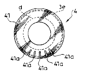
[0004] In this damping valve, the piston separates a space in a cylinder
containing working fluid into a first chamber and a second chamber and has
ports that allow communication between the first chamber and the second
chamber. The leaf valve mentioned above releasably blocks a downstream
end of the ports.
[0005] In the damping valve disclosed in JP2003-042214A, when the
piston speed in the shock absorber is in a low-speed region, the damping force
is generated by allowing the working fluid to flow into the ports from the
first
CA 02866701 2014-09-08
GG10775/ PCT-996 US,EP,CA,TH Description
- 2 -
chamber and to flow out to the second chamber through the orifices. In
addition, when the piston speed in the shock absorber is in a high-speed
region, the damping force is prevented from becoming excessive by allowing
the working fluid to flow into the ports from the first chamber, deflecting
the
outer-circumferential end portion of the leaf valve, and allowing the working
fluid to flow out to the second chamber through the gap formed between the
leaf valve and the valve seat.
SUMMARY OF INVENTION
= [0006] There is a possibility that the ride feeling on a vehicle
is pointed out
to be deteriorated if the shock absorber with the damping valve disclosed in
JP2003-042214A is built into a suspension of the vehicle.
[0007] The damping characteristic of the damping valve disclosed in
JP2003-042214A is abruptly changed from the orifice characteristic with
which the working fluid passes through the orifices to the valve
characteristic
with which the working fluid deflects the outer-circumferential end portion of
the leaf valve and passes through the gap formed between the leaf valve and
the valve seat.
[0008] In other words, although the working fluid only passes
through the
orifices and movement of the outer-circumferential end portion is suppressed
when a flow rate of the working fluid is low, as the flow rate of the working
fluid
passing through the orifices increases, at the point when the orifices can no
longer adapt to the flow rate, the outer-circumferential end portion of the
leaf
valve is deflected to form a gap between the leaf valve and the valve seat,
thereby allowing the working fluid to flow out.
[0009] When the outer-circumferential end portion of the leaf valve
is
deflected to form a gap between the leaf valve and the valve seat, because the
CA 02866701 2014-09-08
,
, GG10775/PCT-996 US,EP,CA,TH Description
. - 3 -
entire circumference of the outer-circumferential end portion of the leaf
valve
separates from the valve seat at once, valve opening movement of the leaf
valve
becomes abrupt, and there will be a sudden change in the damping
characteristic from the orifice characteristic to the valve characteristic.
[0010] Therefore, for example, if the damping characteristic is
changed
from the orifice characteristic to the valve characteristic when a vehicle is
rolling at a low speed, there are concerns that a passenger may sense loss of
a
damping force, the ride comfort on a vehicle may be deteriorated, and a noise
may be generated due to a sudden change in the internal pressure.
[0011] An object of the present invention is to provide a
damping valve that
prevents a deterioration of the ride comfort and generation of noise on a
vehicle.
[0012] According to one aspect of the present invention, a
damping valve
includes a partition that separates a first chamber and a second chamber, a
valve seat that is formed on an end surface of the partition facing the first
chamber or the second chamber; and a leaf valve whose outer-circumferential
end portion is separably seated on the valve seat, wherein the leaf valve has
an
orifice-concentrated portion in which a plurality of orifices for allowing
working
fluid to flow therethrough are formed, in a concentrated manner, in an
arbitrary region along circumferential direction in an outer-circumferential
end portion of the leaf valve.
[0013] Embodiments and advantages of the present invention will
be
described in detail below with reference to the attached drawings.
BRIEF DESCRIPTION OF DRAWINGS
[0014]
[FIG. 1] FIG. 1 is a partial longitudinal sectional view showing a shock
CA 02866701 2014-09-08
,
,
, GG10775/PCT-996 US,EP,CA,TH Description
.. - 4 -
absorber according to one embodiment of the present invention.
[FIG. 2] FIG. 2 is a lateral sectional view of a piston shown along X-X line
in
Fig. 1.
[FIG. 3A] FIG. 3A is a plan view showing a first leaf valve.
[FIG. 3B] FIG. 3B is a plan view showing a second leaf valve.
[FIG. 3C] FIG. 3C is a plan view showing a third leaf valve.
[FIG. 4] FIG. 4 is a plan view showing another embodiment of the first leaf
valve.
[FIG. 5] FIG. 5 is a perspective view showing opening movement of the first
leaf valve.
[FIG. 6] FIG. 6 is a view showing continuity between orifice characteristic
and
valve characteristic.
DESCRIPTION OF EMBODIMENT
[0015] A damping valve according to an embodiment of the
present
invention will be described below with reference to drawing. The damping
valve according to the embodiment of the present invention is used, for
example, in a damping section in a shock absorber that is built into a
suspension of a vehicle.
[0016] As shown in Fig. 1, the shock absorber has a cylinder 1
that
contains, for example, working fluid that is working oil, a piston rod 2 that
is
inserted into the cylinder 1 so as to be capable of moving in and out, and a
piston 3 that is held at a tip end portion 2a located at the lower end part of
the
piston rod 2 in Fig. 1 and that is slidably inserted into the cylinder 1 so as
to be
a partition that divides the space inside the cylinder 1 into a first chamber
R1
and a second chamber R2. The working fluid may be liquid other than the
working oil.
CA 02866701 2014-09-08
GG10775/PCT-996 US,EP,CA,TH Description
- 5 -
[0017] The shock absorber illustrated is of an upright type in which the
cylinder 1 is linked with the axle side of a vehicle as a lower-end-side
member,
and the piston rod 2 is linked with the body side of a vehicle as an
upper-end-side member. For the damping valve according to the embodiment
of the present invention, although the shock absorber is of an upright type,
it
may also be of an inverted type. In addition, although the shock absorber in
the embodiment of the present invention is of a mono-tube type, it may also be
of a multi-tube type instead.
[0018] The damping valve according to the embodiment of the present
invention is provided on a damping section of the shock absorber, in other
words, on an expansion-side valve 4 provided on the one end side of the piston
3 facing the second chamber R2. In Fig. 1, the second chamber R2 is located
at the lower end side of the piston 3 that is slidably inserted into the
cylinder 1.
[0019] In Fig. 1, a compression-side valve 5 is provided on the other end
of
the piston 3 facing the first chamber R1 at the upper end side of the piston
3.
Considering that the damping action is achieved by the compression-side valve
by allowing the flow of the working oil therethrough, the damping valve may
be provided on the compression-side valve 5.
[0020] On the premise of the above description, the damping valve
according to the embodiment of the present invention will be described below.
The piston 3 has expansion-side ports 3a that allow communication between
the first chamber R1 and the second chamber R2 that are formed inside the
cylinder 1. In Fig. 1, the upstream ends, that are the upper ends, of the
expansion-side ports 3a open to a ring-shaped groove 3b that is formed at the
upper end of the piston 3 facing the first chamber R 1. In Fig. 1, the
downstream ends, that are the lower ends, of the expansion-side ports 3a open
to a ring-shaped groove 3c that is formed on the lower end side of the piston
3
CA 02866701 2014-09-08
GG10775/PCT-996 US,EP,CA,TH Description
- 6 -
facing the second chamber R2 (see Fig. 2).
[0021] As also shown in Fig. 2, the piston 3 has an
inner-circumferential-side securing portion 3d on which an
inner-circumferential end portion (not shown with reference sign) of the
expansion-side valve 4, which is at the lower end side in Fig. 1, is seated
and a
ring-shaped valve seat 3e that is formed outside the inner-circumferential-
side
securing portion 3d such that the ring-shaped groove 3c is formed between the
ring-shaped valve seat 3e and the inner-circumferential-side securing portion
3d.
[0022] The ring-shaped groove 3b is communicated with the first chamber
R1 through holes Sa formed in the compression-side valve 5. A circle
indicated by one-dot chain line in Fig. 2 indicates the contour of the
expansion-side valve 4 that is seated on the valve seat 3e. Illustration of a
piston ring provided on outer circumference of the piston 3 is omitted.
[0023] On the other hand, the expansion-side valve 4 consists of a
plurality
of ring-shaped leaf valves that are stacked on the lower end side of the
piston 3.
In addition, as shown in Fig. 3, the leaf valves consist of a first leaf valve
41 and
a second leaf valve 42 having the same diameter and a third leaf valve 43
having a diameter smaller than that of the first leaf valve 41 and the second
leaf valve 42. For the third leaf valve 43, it may be formed to have the same
diameter as the second leaf valve 42.
[0024] The expansion-side valve 4 releasably blocks the ring-shaped groove
3c of the piston 3 by having an inner-circumferential end portion that is
fixed
by being seated on the inner-circumferential-side securing portion 3d of the
piston 3 and an outer-circumferential end portion (not shown with reference
sign) that is separably seated on the valve seat 3e of the piston 3.
[0025] In other words, the first leaf valve 41 is stacked on the lower end
side
CA 02866701 2014-09-08
GG10775/PCT-996 US,EP,CA,TH Description
- 7
of the piston 3 such that whose inner-circumferential end portion (not shown
with reference sign) is anchored on the inner-circumferential-side securing
portion 3d and whose outer-circumferential end portion (not shown with
reference sign) is separably seated on the valve seat 3e, and thereby,
releasably
blocks the ring-shaped groove 3c.
[0026] The first leaf valve 41 has, on the outer-circumferential end
portion,
a plurality of orifices 41a formed of slits for allowing the flow of the
working oil
therethrough. The plurality of orifices 41a are formed so as to penetrate the
first leaf valve 41 in its thickness direction and to extend towards the
center
from the outer-circumferential surface. In other words, the plurality of
orifices 41a open at the outer-circumferential surface of the first leaf valve
41,
communicate the ring-shaped groove 3c located at inside the valve seat 3e and
the second chamber R2 located at outside the valve seat 3e, and allow the
working oil to pass therethrough when the piston speed is in the low-speed
region, thereby generating the damping force based on the orifice
characteristic.
[0027] In addition, the plurality of orifices 41a of the first leaf valve
41 are
formed, in a concentrated manner, in an arbitrary region along the
circumferential direction in the outer-circumferential end portion as an
orifice-concentrated portion. The orifice-concentrated portion has at least
two slits within the 180 range in the circumferential direction of the leaf
valve
41. In addition, as shown in Fig. 3, the orifices 41a are formed only in a
part
of region, i.e. the orifice-concentrated portion, and are not formed in other
parts in the circumferential direction.
[0028] The second leaf valve 42 is stacked on the back surface of the first
leaf valve 41 at the second chamber R2 side so as to cover the orifices 41a.
In
other words, the working oil passes through the orifices 41a and flows out to
CA 02866701 2014-09-08
GG10775/ PCT-996 US, EP, CA,TH Description
- 8
the second chamber R2 from openings at the outer-circumferential surface of
the first leaf valve 41.
[0029] The outer-circumferential end portion of the second leaf valve 42
deflects together with the outer-circumferential end portion of the first leaf
valve 41, on which the second leaf valve 42 is stacked, and follows the
movement of the first leaf valve 41 when the first leaf valve 41 is deflected
and
separated from the valve seat 3e.
[0030] The third leaf valve 43 is stacked on the back surface of the second
leaf valve 42 at the second chamber R2 side and functions so as to suppress
the deflection movement of the outer-circumferential end portion of the second
leaf valve 42, in other words, the deflection movement of the
outer-circumferential end portion of the first leaf valve 41.
[0031] In other words, by selecting the size of the diameter of the third
leaf
valve 43, it is possible to control the amount of deflection of the
outer-circumferential end portion of the second leaf valve 42, and in turn, to
control the amount of deflection of the outer-circumferential end portion of
the
first leaf valve 41.
[0032] In the damping valve according to the embodiment of the present
invention, only the first leaf valve 41 suffices to be provided, and the
second
leaf valve 42 and the third leaf valve 43 are not necessarily required.
[0033] In the shock absorber having the damping valve formed as described
above, during an expanding action in which the piston 3 is lifted up within
the
cylinder 1, the working oil flows out from the high-pressure side first
chamber
R1 to the low-pressure side second chamber R2 through the expansion-side
ports 3a.
[0034] In the damping valve according to the embodiment of the present
invention, when the piston speed in the cylinder 1 is in the low-speed region,
CA 02866701 2014-09-08
GG10775/PCT-996 US,EP,CA,TH Description
- 9 -
,
the working oil in the expansion-side ports 3a flows out to the second chamber
R2 through the ring-shaped groove 3c and the orifices 41a, and the damping
force based on the orifice characteristic is generated by the pressure loss
caused by the flow of the working oil through the orifices 41a.
[0035] As the piston speed in the cylinder 1 is increased to be
in a middle-
or high-speed region, the working oil in the ring-shaped groove 3b deflects
the
outer-circumferential end portions of the first leaf valve 41 and the second
leaf
valve 42 via the expansion-side ports 3a. Thus, the working oil flows out to
the second chamber R2 through a gap formed between the valves and the valve
seat 3e, and damping force based on valve characteristic is generated by the
pressure loss caused by the flow of the working oil through the gap formed
between the first leaf valve 41 and the valve seat 3e.
[0036] In the damping valve according to the embodiment of the
present
invention, the plurality of orifices 41a formed in the outer-circumferential
end
portion of the first leaf valve 41 are formed in a concentrated manner in an
arbitrary region along the circumferential direction in the
outer-circumferential end portion, in other words, in one region, as shown in
Fig. 3.
[0037] As shown in Fig. 3(A), the first leaf valve 41 has the
orifice-concentrated portion that is an arbitrary region along circumferential
direction in the outer-circumferential end portion in which the plurality of
orifices 41a are formed. Therefore, the orifice-concentrated portion has the
deflection stiffness lower than that in the other parts along the
circumferential
direction in the outer-circumferential end portion of the first leaf valve 41,
and
tends to be deflected more easily.
[0038] Assuming that a pair of slits are provided on the leaf
valve 41 as the
orifices 41a, the part between the pair of slits tends has the deflection
stiffness
CA 02866701 2014-09-08
GG10775/PCT-996 US,EP,CA,TH Description
- 10
lower than that in other parts that are not located between the pair of slits.
[0039] If a plurality of slits are further provided in the part between the
pair
of slits, the deflection stiffness in the part between the pair of slits is
lowered
even further compared to that in the other parts, causing it to deflect more
easily.
[0040] As described above, at least two slits need to be provided in the
leaf
valve 41 as the orifices 41a, and deflection may be caused more easily by
providing more slits to the part between the two slits.
[0041] As shown in Fig. 3(A), although the slits consisting the orifices
41a
are provided in the radial direction, as shown in Fig. 4, they may be provided
in
parallel instead.
[0042] In the case where the plurality of slits are provided in parallel,
the
slits may be positioned such that the end portions thereof at the inner
circumferential side are aligned at the positions indicated by one-dot chain
line
in Fig. 4, and also in this case, the deflection stiffness of the
orifice-concentrated portion, in which the plurality of slits are
concentrated,
becomes lower than that in the other parts in the outer-circumferential end
portion without the slits, thereby making the deflection to be caused more
easily.
[0043] The lengths of the slits in the radial direction may be arbitrarily
selected as long as the set deflection stiffness can be realized. By setting
the
lengths of the slits in the radial direction longer, it is possible to
effectively
lower the deflection stiffness of a part of the outer-circumferential end
portion
of the first leaf valve 41.
[0044] Based on the fact that the orifices 41a can be realized by making
the
slits to face against the valve seat 3e, the function of the orifices 41a is
not
affected even if the lengths of the slits are increased, as long as the widths
in
CA 02866701 2014-09-08
GG10775/PCT-996 US,EP,CA,TH Description
- 11
the radial direction of the valve seat 3e are not increased.
[0045] This is because the parts of the slits that overlap with the valve
seat
3e function as the orifices as the second leaf valve 42 having the same
diameter as the first leaf valve 41 is stacked on the back surface of the
first leaf
valve 41, and not entire lengths of the slits function as the orifices.
[0046] Although the intervals between the respective orifices 41a may be
set arbitrarily, based on the fact that the plurality of orifices 41a are
formed in
a concentrated manner and the arbitrary region in the outer-circumferential
end portion of the first leaf valve 41 has a comb-like shape, the part, in
which
the orifices 41a are concentrated, is formed to have a sufficient strength so
as
not to undergo plastic deformation or fracture easily even when deflection
movements are repeated.
[0047] As described above, the lengths of the slits in the radial direction
are
adjusted such that desired deflection stiffness can be achieved, and the
widths
of the slits in the circumferential direction are adjusted within a certain
range
so as to have the strength that is sufficient to prevent plastic deformation
or
fracture even when deflection movements are repeated. In other words, by
adjusting the lengths in the radial direction and the widths in the
circumferential direction of the slits such that the orifice-concentrated
portion
does not undergo plastic deformation or fracture easily, it is possible to
adjust
the deflection stiffness of the leaf valve 41, and therefore, the damping
characteristic of the leaf valve 41.
[0048] As described above, in the damping valve according to the
embodiment of the present invention, the first leaf valve 41 has the
orifice-concentrated portion in which the plurality of orifices 41a are
formed, in
a manner concentrated in one location, in an arbitrary region along the
circumferential direction in the outer-circumferential end portion. Therefore,
CA 02866701 2014-09-08
GG10775/PCT-996 US,EP,CA,TH Description
- 12
during the expanding action of the shock absorber in which the piston 3 is
lifted within the cylinder 1, the damping valve is operated as in the
following.
[0049] When the piston speed is in the low-speed region, the working oil
flows out to the outside of the valve seat 3e through the orifices 41a without
deflecting the outer-circumferential end portion of the leaf valve 41 having
the
orifices 41a, and the damping force based on the orifice characteristic is
generated by the orifices 41a.
[0050] As the piston speed is increased to exceed the low-speed region and
shifted to the high-speed region, because the flow rate of the working oil
passing through the respective orifices 41a of the leaf valve 41 is increased,
the
respective orifices 41a become no longer sufficient to allow all working oil
to
flow out by passing therethrough, and the orifice-concentrated portion of the
leaf valve 41 that has been held at the position up to that point is deflected
by
a fluid force. Then, a gap is partially formed between the leaf valve 41 and
the
valve seat 3e, and the working oil is allowed to flow out to the outside of
the
valve seat 3e, generating the damping force based on the valve characteristic.
[0051] In the case where the flow rate of the working oil is increased
further,
the parts of the outer-circumferential end portion of the leaf valve 41 other
than the orifice-concentrated portion are also deflected by the fluid force of
the
working oil to form a gap between the leaf valve 41 and the valve seat 3e.
Then, the working oil is allowed to flow out to the outside of the valve seat
3e to
generate the damping force based on the valve characteristic.
[0052] As described above, in the damping valve according to the
embodiment of the present invention, the plurality of orifices 41a are
concentrated in a part in the outer-circumferential end portion of the first
leaf
valve 41, thereby forming the orifice-concentrated portion having lower
deflection stiffness than the other parts. Thus, as shown in Fig. 5, this
CA 02866701 2014-09-08
GG10775/ PCT-996 US,EP,CA,TH Description
=
- 13 -
so-called low-stiffness portion is prone to undergo deflection movement
compared to the other parts and is separated from the valve seat 3e to undergo
valve opening movement before the other parts.
[0053] As described above, when the piston speed is in the low-speed region,
the working oil flows through the orifices 41a and flows out to the second
chamber R2 without deflecting the outer-circumferential end portions of the
first leaf valve 41 and the second leaf valve 42, thereby generating the
damping
force based on the orifice characteristic.
[0054] On the other hand, because the higher the piston speed is,
the
higher the flow rate of the working oil becomes, the orifices 41a become no
longer sufficient to allow all working oil to flow out to the second chamber
R2
by passing therethrough, and thus, the working oil deflects the
outer-circumferential end portion of the first leaf valve 41 and flows out to
the
second chamber R2. At this time, because the orifice-concentrated portion of
the first leaf valve 41 is the low-stiffness portion having the plurality of
orifices
41a in a part of the outer-circumferential end portion, the deflection of the
first
leaf valve 41 starts from this low-stiffness portion.
[0055] Therefore, in the first leaf valve 41, as the piston speed
exceeds the
low-speed region, the orifice-concentrated portion, that is the low-stiffness
portion, having the plurality of orifices 41a in the outer-circumferential end
portion is deflected first, and a gap is partially formed between the
orifice-concentrated portion and the valve seat 3e. Then, the working oil is
allowed to flow out to the second chamber R2 through the gap, and the
damping force based on the valve characteristic is generated due to the
pressure loss.
[0056] As the flow rate of the working oil is further increased by
the further
increase of the piston speed, for example, the entire circumference of the
CA 02866701 2014-09-08
GG10775/PCT-996 US,EP,CA,TH Description
- 14 -
outer-circumferential end portion, that is the other part, in the first leaf
valve
41 is deflected, and a ring-shaped gap is formed between the first leaf valve
41
and the valve seat 3e. The working oil is then fully allowed to flow out to
the
second chamber R2 through the ring-shaped gap, thereby generating the
damping force based on the valve characteristic due to the pressure loss.
[0057] As a result, in the course of shifting from the damping action based
on the orifice characteristic to the damping action based on the valve
characteristic, the first leaf valve 41 is prevented from being opened by
sudden
deflection of the entire circumference of the outer-circumferential end
portion
at once, and reaches to a fully opened state by gradual deflection of the
outer-circumferential end portion. Therefore, the gradual shift from the
orifice characteristic to the valve characteristic is achieved.
[0058] Explanation will be given with reference to Fig. 6. Assuming that
the first leaf valve 41 does not have the low-stiffness portion, that is the
concentrated portion of the orifices 41a, the entire circumference of the
outer-circumferential portion in the first leaf valve 41 will open at once.
Thus,
as shown with broken line in Fig. 6, the damping characteristic is abruptly
changed as the orifice characteristic 0 is shifted to the valve characteristic
V.
[0059] In contrast, in the damping valve according to the embodiment of
the present invention, the first leaf valve 41 has the low-stiffness portion,
that
is the concentrated portion of the orifices 41a, and a part of the
outer-circumferential end portion of the first leaf valve 41 is opened in
preference. Thus, in the course of switching from the damping action based
on the orifice characteristic to the damping action based on the valve
characteristic, the switch to the damping action based on the valve
characteristic is not performed fully and suddenly, and the switch to the
damping action based on the valve characteristic is gradual. In other words,
CA 02866701 2014-09-08
GG10775/PCT-996 US,EP,CA,TH Description
- 15
as shown with solid line in Fig. 6, the damping characteristic is gradually
changed as the orifice characteristic 0 is shifted to the valve characteristic
V.
[0060] When the outer-circumferential end portion of the above-mentioned
first leaf valve 41 undergoes the deflection movement, the
outer-circumferential end portion of the second leaf valve 42 also undergoes
the deflection movement. In other words, because the second leaf valve 42 is
stacked on the back surface of the first leaf valve 41, when the
outer-circumferential end portion of the first leaf valve 41 undergoes the
deflection movement, the outer-circumferential end portion of the second leaf
valve 42 also undergoes the deflection movement. Although respective
explanations have been omitted, this omission does not indicate that the
second leaf valve 42 does not undergo the deflection movement.
[0061] In the shock absorber shown in Fig. 1, the expansion-side valve 4
and the compression-side valve 5 are provided so as to sandwich the piston 3
at the top and lower end sides. Furthermore, the expansion-side valve 4 and
the compression-side valve 5 are clamped between a piston nut 21 that is
screwed to a tip-end thread portion 2b of the piston rod 2 and a stepped
portion 2c formed on the piston rod 2, and provided such that their inner
circumferential ends are fixed and the outer-circumferential end portions are
free.
[0062] Compression-side ports 3f, which penetrate through the piston 3 in
parallel with the expansion-side ports 3a, open at the upstream ends thereof
to
a ring-shaped groove 3g that is formed at the lower end side of the piston 3
and
open at the downstream ends thereof to a ring-shaped groove 3h that is formed
at the upper end of the piston 3.
[0063] During a contracting action of the shock absorber in which the
piston 3 is lowered within the cylinder 1, the working oil flows out from the
CA 02866701 2014-09-08
GG10775/PCT-996 US,EP,CA,TH Description
- 16 -
second chamber R2, deflects the outer-circumferential end portion of the
compression-side valve 5 through the compression-side ports 3f and the
ring-shaped groove 3h, and flows into the first chamber R 1 .
[0064] According to the above-described embodiment, the effects and
advantages shown below are afforded.
[0065] The leaf valve 41 provided on the damping valve according to the
embodiment of the present invention has the orifice-concentrated portion in
which the plurality of orifices 41a are formed, in a concentrated manner, in
an
arbitrary region in the outer-circumferential end portion. Because the
orifice-concentrated portion has the deflection stiffness lower than that in
the
other parts of the outer-circumferential end portion of the leaf valve 41
without
the orifices 41a, the orifice-concentrated portion is prone to be deflected
compared to the other parts.
[0066] When the piston speed is in the low-speed region, the working oil
flows out through the plurality of orifices 41a without deflecting the
outer-circumferential end portion of the leaf valve 41, and the damping force
based on the orifice characteristic is generated.
[0067] On the other hand, when the flow rate of the working oil is
increased
and the plurality of orifices 41a provided on the leaf valve 41 become no
longer
sufficient to allow all working oil to flow out by passing therethrough, the
outer-circumferential end portion having the plurality of orifices 41a is
deflected in preference to the other parts by the fluid pressure of the
working
oil, and a gap is partially formed between the leaf valve 41 and the valve
seat 3e.
Therefore, the working oil is allowed to flow out through this partial gap,
and
the damping force based on the valve characteristic is generated by the
partially opened leaf valve 41.
[0068] As the flow rate of the working oil is further increased, the entire
CA 02866701 2014-09-08
GG10775/ PCT-996 US,EP, CA,TH Description
- 17
circumference of the outer-circumferential end portion of the leaf valve 41 is
deflected, and the ring-shaped gap is formed between the leaf valve 41 and the
valve seat 3e. Thus, the working oil is allowed to flow out through the
ring-shaped gap, thereby generating the damping force based on the valve
characteristic by the fully opened leaf valve 41.
[0069] As described above, according to the damping valve according to the
embodiment of the present invention, the damping characteristic based on the
orifice characteristic that is optimal when the piston speed is in the low-
speed
region and the damping characteristic based on the valve characteristic that
is
optimal when the piston speed is in the high-speed region are switched
gradually without experiencing any abrupt change, no sudden change in
acceleration of the piston is caused, and generation of noise may be
suppressed as there is no sudden change in the internal pressure. In other
words, according to the damping valve according to the embodiment of the
present invention, when the orifice characteristic is switched to the valve
characteristic, it is possible to make the change in the damping
characteristic
gradual, and thus, it is possible to avoid concern of deterioration of ride
comfort and generation of noise on a vehicle.
[0070] Embodiments of this invention were described above, but the above
embodiments are merely examples of applications of this invention, and the
technical scope of this invention is not limited to the specific constitutions
of
the above embodiments.
[0071] Modified examples of this embodiment will be described below.
[0072] In the above-mentioned embodiment, the valve seat 3e is formed on
the piston 3 that is a partition inserted into the cylinder 1. Alternatively,
the
valve seat 3e may be formed on a valve disc that is a partition in a base
valve
provided in the lower end portion of the cylinder 1 of a shock absorber set as
CA 02866701 2014-09-08
GG10775/PCT-996 US,EP,CA,TH Description
- 18
an upright type.
[0073] When the valve disc in the base valve is configured as the
partition,
the shock absorber is formed as, for example, a multi-tube type shock
absorber, a first chamber partitioned by the valve disc becomes a lower side
chamber that is partitioned in the cylinder 1 by the piston 3 and a second
chamber becomes a reservoir outside the cylinder 1.
[0074] In the above-mentioned embodiment, the orifices 41a are slits
penetrating the first leaf valve 41 in its thickness direction. Alternatively,
the
orifices 41a may be formed as grooves that open to the outer-circumferential
surface of the leaf valve 41 and that do not penetrate the first leaf valve 41
in
its thickness direction. In the case where the orifices 41a are formed as the
grooves, because it is necessary to form flow paths for the working oil, the
grooves are formed so as to open to the outer-circumferential surface of the
leaf
valve 41 and such that the working oil flowing in from the first chamber can
flow out to the second chamber R2.
[0075] In addition, instead of forming the orifices 41a as the slits formed
on
the outer-circumferential end portion of the first leaf valve 41 and the
grooves
that do not penetrate the leaf valve 41 in its thickness direction, in
consideration of the intention of the present invention, the orifices 41a may
be
formed as small holes drilled into the first leaf valve 41.
[0076] In the above-mentioned embodiment, although the second leaf valve
42 is formed to have the same diameter as the first leaf valve 41, the second
leaf valve 42 may be formed to have a different diameter. In other words, as
long as the orifices 41a provided on the first leaf valve 41 can be realized
as the
orifices, the second leaf valve 42 may be formed so as to cover a part of the
orifices 41a or so as not to cover the orifices 41a.
[0077] In addition, in the case where the orifices 41a are formed as the
slits,
CA 02866701 2014-09-08
GG10775/PCT-996 US,EP,CA,TH Description
- 19 -
,
although the orifices 41a can be realized by stacking the second leaf valve 42
on the first leaf valve 41, as long as the orifices 41a provided on the first
leaf
valve 41 can be realized as the orifices, the second leaf valve 42 may not be
stacked on the back surface of the first leaf valve 41.
[0078] In the above-mentioned embodiment, the case in which the
orifices
are formed on the first leaf valve 41 has been described as an example.
Alternatively, in the case where the orifices consist of engraved portions
formed
on the valve seat 3e, a plurality of engraved portions may be provided, in a
manner concentrated in one location, in the circumferential direction of the
valve seat 3e.
[0079] This application claims priority based on Japanese
Patent
Application No.2012-73070 filed with the Japan Patent Office on March 28,
2012, the entire contents of which are incorporated into this specification.
[0080] The embodiments of this invention in which an exclusive
property or
privilege is claimed are defined as follows: