Note: Descriptions are shown in the official language in which they were submitted.
CA 02866834 2014-09-09
WO 2013/136036 PCT/GB2013/000099
1
Order Pickers
The present invention relates to improvements in and relating to Order
Pickers.
Order Pickers are industrial trucks that are used to select items which are
located in
stacks. Conventionally an order picker includes a cab for an operative and a
pallet into
which the selected items may be placed. The Order picker is driven down an
aisle
between two stacks, so that the operative may pick items from pallets or
storage bins
located in the stacks on either side of the aisle.
Means may be arranged for elevating the cab, so that items may be selected
from pallets
or bins on upto three levels. The pallet would normally rise with the cab but
may also be
mounted on forks for vertical movement independently of the cab. This will
enable the -
pallet to be lowered, as items are stacked upon it. The use of independently
moveable
1 5 forks will also allow the pallet to be removed from the Order Picker
when the order has
been filled.
With known Order Pickers, generally the maximum to which the cab may be
elevated
would typically be upto three levels, say 2.8m to 4m. Typically stacks may
extend to 7m
to 12m. It is common practice in warehouses to store reserve items on pallets
or in bins
above the pallets or bins from which the items are picked. If a conventional
Order Picker
comes to an empty pallet or bin, then it is necessary to call on a high reach
lift truck to
replace the empty pallet or bin with a replacement pallet or bin located at a
bulk stock
location to which the Order Picker is capable of reaching. -
The present invention provides an improved Order Picker which is capable of
retrieving
storage bins above the normal order picking levels.
According to one aspect of the present invention an Order Picker comprises a
body
section having a pair of ground engaging wheels and a first lift mechanism
pivotally
mounted to one end of the body section about a vertical pivot, one or more
ground
engaging wheels being provided on the first lift mechanism, means being
provided for
pivoting the first lift mechanism relative to the body section whereby the
order picker
may be steered, an open cab being provided on the body section whereby an
operative
CA 02866834 2014-09-09
WO 2013/136036
PCT/GB2013/000099
2
located in the cab may have access to stacks on either side of the order
picker, the cab
being mounted to the body section on a second lift mechanism by which the cab
may be
raised and lowered with respect to the body section independently of the first
lift
mechanism; and a receptacle onto or into which picked items may be placed, the
receptacle being mounted on the cab on the end thereof remote from the end of
the body
section to which the first lift mechanism is mounted.
With the order picker of the present invention, the first lift mechanism may
be used to lift
pallets or storage bins which are outside the range of the cab when elevated
to its
maximum height. A further advantage of the present invention is that the first
lift
mechanism may be used to lower a pallet or storage bin to a level at which it
is
accessible from the raised cab thus avoiding the need to lower the pallet or
storage bin to
ground level or first clear a space at a level which is accessible from the
raised cab.
According to a preferred embodiment of the present invention, the first lift
mechanism is
capable of operating to heights of from 7 to 12 meters, while the second lift
mechanism
is capable of raising the cab to from 2.8 to 4 meters.
For safety considerations, the control means for, driving the order picker,
pivoting the
first lift mechanism relative to the body section and raising and lowering the
first lift
mechanism are preferably only accessible from the lowered position of the cab.
=
According to a further preferred embodiment of the invention, the receptacle
is mounted
with respect to the cab on a third lift mechanism, by which the receptacle may
be raised
and lowered with respect to the cab, to adjust the height of the receptacle as
items are
_ stacked onto or into the receptacle and to allow the receptacle to be
deposited on to the
ground when an order has been filled. The receptacle may, for example, be a
pallet or
bin.
The invention is now described, by way of example only, with reference to the
accompanying drawings, in which:-
Figure 1 shows a perspective view of an order picker in accordance with the
present
invention;
CA 02866834 2014-09-09
WO 2013/136036 PCT/GB2013/000099
3
Figure 2 shows the order picker illustrated in figure 1 in conventional order
picker raised
mode;
Figure 3 shows the order picker illustrated in figure 1 being used to access
pallets stored
above the level normally accessible to order picker in order picker mode;
Figure 4 shows a perspective view of a modified order picked in accordance
with the
present invention;
-Figure 5 shows the order picker illustrated in figure 4 in conventional order
picker mode; .
Figure 6shows the order picker illustrated in 'figure 4 in conventional order
picker raised
mode;
15.
Figure 7 shows the order picker illustrated in figure 4 being used to access
pallets stored
above the level normally accessible to order picker in order picker mode;
Figure 8 shows a perspective view illustrating a further modified order picker
in
accordance with the present invention;
Figure 9a illustrates the manner in which the cab is secured to the Outer
section of the cab
- raise mast of the order picker illustrated in figure 8;
Figure 9b illustrates the intermediate section of the cab raise mast of the
order picker
illustrated in figure 8;
=
Figure 9c illustrates how the inner section of the cab raise mast of the order
picker
illustrated in figure 8 is secured to the body section;
Figure 10 is a rear view of the cab raise mast of the order picker illustrated
in figure 8;
Figure 11 is a view of the of the cab raise mast of the order picker body
illustrated in
figure 8, from above; and
CA 02866834 2014-09-09
WO 2013/136036
PCT/GB2013/000099
4
Figure 12 is a detailed view of the intermediate section of the cab raise mast
of the order
picker body illustrated in figure 8. =
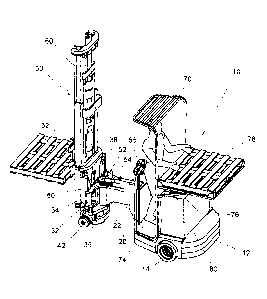
As illustrated in figures 1 to 3 an order picker 10 has a body section 12
having a pair of
rear ground engaging wheels 14, one wheel 14 being mounted on each side of the
body
section12, towards the rear of the body section 12.
An arm 20 extends forwardly from the front of the body section 12, a vertical
pivot tube
22 being provided at the end of the arm 20 remote from the body section 12.
A lift mechanism 30 has a yoke assembly 32 having an upper and lower plate
members
34, 36 extending horizontally, a pivot pin 38 extending centrally between the
plate
members 34, 36, the pivot pin 38 being mounted in bearings, in the pivot tube
22.
A single ground engaging front wheel 40 is mounted on the yoke assembly 32, on
an
axle which is parallel to the plate members 34, 36. The front wheel is driven
by an
electric or hydraulic motor 42 and gear box 44 mounted coaxially of the wheel
40.
The pivot pin 38 is non-rotatably secured with respect to the yoke assembly
32. A gear
50 is secured to the pivot pin 38. or directly to the yoke assembly coaxially
of the pivot
pin 38 and is engaged by a gear 52 driven by an electric steering motor 54. A
steering
control on a control module 56 mounted in a fixed position on the front end of
the body
section 12, adjacent arm 20, is used to control the electric steering motor
54. The
steering control may be used to energise the,electric motor 54 in either
direction, to pivot
the yoke assembly 32 to one side or the other relative to the body section 12,
and thereby
steer to order picker 10. The yoke assembly 32 may be pivoted in excess of 90
to either
side of the straight ahead position.
A telescopic lift mast 60 is mounted on the yoke assembly 32, a pair of forks
62
extending forwardly of the lift mast, being mounted on the lift mast for
movement
vertically thereof.
CA 02866834 2014-09-09
WO 2013/136036 PCT/GB2013/000099
Means for controlling forward and reverse movement of the order picker 10 and
for
controlling movement of the telescopic mast 60 and forks 62, are also provided
on the
control module 56.
5 A cab 70 is mounted on the forward end of the body section 12, the cab 70
being
mounted for vertical movement on a telescopic mast 72. The floor 74 of the cab
70
provides a platform upon which the operative may stand. The cab 70 is open to
the front
and provides access to the control module 56, when to cab 70 is in a lowered
position.
The cab 70 is open to each side to allow access to pallets or storage bins
located in stacks
1 0 on either side of the order picker 10. A frame structure 76 extends
rearwardly from to
rear of the cab 70, at a working height for supporting a pallet or other
receptacle 78 onto
which picked items may be placed.
Means for controlling telescopic mast 72 is mounted on the cab 70, for
movement with
1 5 the cab 70.
A battery pack 80 is provided to the rear of the body section 12, beneath the
frame
structure 76 on the cab 70, to power the various systems of the order picker.
A motor
and hydraulic pump (not shown) may also be provided on the body section 12, to
power
20 hydraulic systems of the order picker 10.
The order picker 10 described above may be used in conventional order picker
mode to
pick items from pallets or storage bins located in stacks on either side of an
aisle as the
order picker 10 is driven straight down the aisle. As illustrated in figure 2,
the cab 70
25 may be raised, typically from 2.8 meters or higher, to pick items from
storage pallets or
=
bins on, for example, upto three or more levels. Picked items are placed by
the operative
on a pallet or other receptacle 78 supported on frame 76.
Alternatively, the order picker 10 may be used, with the cab 70 at its
lowermost position,
30 as a high reach lift truck, at heights typically from 7 meters to 12
meters. The
articulation of the lift mechanism 30 providing good manoeuvrability and
enabling the
order picker 10 in this mode to operate in narrow aisles.
CA 02866834 2014-09-09
WO 2013/136036
PCT/GB2013/000099
Furthermore, as illustrated in figure 3, the order picker 10 may be used in
high reach
mode to lower a storage pallet of bin to a level at which it is accessible
from the cab 70
in a raised position, the cab 70 then being raised and the item picked from
the storage
pallet or bin supported in the lift mechanism 30.
In the embodiment illustrated in figures 4 to 6, the cab 170 is mounted on
lift mast 172,
towards the rear of the body section 112. The battery pack 180 is mounted
towards the
front of the body section 112.
A floor extension 190 extends over the battery pack 180, the floor extension
190 being
attached to the cab 170 for limited vertical movement relative thereto,
permitting the
main floor 174 of the cab 170 to move below the floor extension 190 when it
abuts the
battery pack 180, the floor extension 190 being constrained to move with the
cab 170 in
alignment with the main floor 174, when the main floor 174 rises above the
level of the
1 5 battery pack 180. As illustrated in figure 6, the floor extension 190
will thereby permit
access to storage pallets or bins supported on the lift mechanism 30, in
similar manner to
that described above with reference to figure 3, in spite of the increased
distance between
the cab 170 and lift mechanism 30.
In place of the fixed frame 76 of the embodiment illustrated in figures 1 to
3, in the
embodiment illustrated in figures 4 to 6, the receptacle 178 is mounted on a
pair of forks,
the forks being mounted on the rear of the cab 170 on lift means 192. The
receptacle
178, for example may thereby be lowered from its initial working height, as
items are
stacked on the receptacle 178, to maintain the working height. Moreover, the
lift
mechanism 192 may lower the forks and receptacle 178 to the ground, to unload
the
receptacle 178 from the order picker 10, when an order has been filled.
In the embodiment illustrated in figures-8 to 12, the lift mechanism 30 is
similar to that
described with reference to figures 1 to 7. In this embodiment a cab raise
mast 272 is
secured to the rear of the body section 212. The mast 272 comprises three
sections, an
inner section 274, an intermediate section 276 and an outer section 278. The
sections
274, 276 and 278 of the mast are each formed from a pair of spaced apart I-
section
uprights 280 mounted parallel to one another with the front and rear flange
formations
282, 284 of one upright of being coplanar of the corresponding front and rear
flange
=
CA 02866834 2014-09-09
WO 2013/136036 PCT/GB2013/000099
7
formations 282, 284 of the other upright 280. The uprights 280 of each section
274, 276
and 278, are interconnected by upper and lower cross members 286, 288; 290,
292; and
=
294,296 respectively, located adjacent the top and bottom of the I-section
uprights 280.
The cross members, 286, 288 of section 274; 290, 292 of section 276; and 294,
296 of
section 278; yary in length so that the sections 274, 276 and 278 may be
nested in
telescopic manner. The uprights 280 of inner section 274 are located within
the uprights
280 of intermediate section 276; with the outer portions of flange formations
282 of the
inner section 274 engaging in the inner channel 298 formed between flange
formations
282, 284 of intermediate section 276 and the inner portions of flange
formations 284 of
intermediate section 276 engaging in the outer channel 300 formed between
flange
formations 282, 284 of inner section 274. The uprights 2-80 of the
intermediate section
276 are located within uprights 280 of the outer section 278, with the outer
portions of
flange formations 284 of intermediate section 276 engaging in the inner
channel 298
formed between flange formations 282, 284 of outer section 278 and the inner
portions
of flange formations 282 of outer section 278 engaging in the outer channel
300 formed
between flange formations 282, 284 of intermediate section 276.
Rollers 302 are attached adjacent the top of sections 274 and 276, the rollers
302 being
rotatably attached in,the outer channel sections 300 defined between flanges
282 and 284
of sections 274 and 276, for rotation about axes parallel to the plane the
flange
formations 282 and 284. The rollers 302 attached to inner section 274 extend
into the
inner channel sections 289 defined between the flange formations 282, 284 and
engage
the flange formations 284 of intermediate section 276. The rollers 302
attached to
intermediate section 276 extend into the inner channel sections 289 defined
between the
flange formations 282, 284 of outer section 278 and engage the flange
formations 282 of
outer section 278.
Rollers 304 are pivotally attached adjacent the bottom of sections 276 and
278, the
rollers 304 being pivotally attached in the inner channel sections 298 for
rotation about
axes parallel to the plane the flange formations 282 and 284. The rollers 304
on
intermediate section 276 extend into the outer channel sections 300 defined
between the
flange fon-nations 282, 284 and engage flange formations 282 on inner section
274. The
rollers 304 on outer section 278 extend into the outer channel sections 300
defined
CA 02866834 2014-09-09
WO 2013/136036
PCT/GB2013/000099
8
between the flange formations 282, 284 and engage flange formations 284 on
intermediate section 276.
The rollers 302 and 304 thereby ensure that as the sections 274, 276 and 278
move with
respect to one another, the flange formations 282 and 284 of each section 274,
276, 278
are held in sliding engagement with the corresponding flange formations 282
and 284 of
the adjacent section 274, 276, 278.
Cam rollers 306 are mounted to the top on both sides of the inner section 274
and
intermediate section 276, on the outside of uprights 280; and on both sides to
the bottom
of intermediate section 276 and outer section 278 on the inside of uprights
280. The cam
rollers 306 are mounted for rotation about axes perpendicular to the plane of
the flange
formations 282, 284. The cam rollers 306 at the top of inner section 274 run
against the
bases of the inner channels 298 of intermediate section 276, the cam rollers
306 at the
bottom of intermediate seetion 276 run against the bases of the outer channel
sections
300 of inner section 274. The cam rollers 306 at the-top of intermediate
section 276 run
against the bases of the inner channels 298 of outer section 278, and the cam
rollers 306
at the bottom of outer section 278 run against the bases of the outer channel
sections 300
of intermediate section 276. The cam rollers 306 thereby serve to prevent
lateral sway of
the sections 276 and 278 of the mast 272.
The base of inner section 274 of the mast 272 is secured centrally to the rear
of the body
section 212.
A hydraulic ram 310 is secured to the lower and upper cross members 286, 288
of the
inner section 274 of the mast 272, the ram 310 extending centrally of and
parallel to the.
Upright sections 280 of inner section 274. A piston 312 extends from the upper
end of
ram 310 and is secured at its free end 314 to the upper cross member 290 of
the
intermediate section 276. A pair of sprocket wheels 316 are mounted in cross
member
290, one each side of the piston 312. The sprocket wheels 316 are mounted for
rotation
about an axis parallel to the plane of the flange formations 282, 284 of the
inner section
274.
=
CA 02866834 2014-09-09
WO 2013/136036 -
PCT/GB2013/000099
9
A pair of chains 318 engage the sprocket wheels 314, one end of each chain 318
being
anchored to the upper cross member 286 of the inner section 274, while the
other end of
each chain 318 is anchored to the lower cross member 296 of the outer section
278. In
this manner when the ram 310 is extended, intermediate section 276 will be
lifted
relative to inner section 274 by the piston 312, while the outer section 278
is raised
relative to the intermediate section 276 by the chains 318.
A pair of plates 320 are secured to the front flange formations 282 of outer
section 278,
adjacent the bottom of section 278, the plates 320 extending outwardly of
uprights 280.
1 0 &platform 322 of a cab 324 is secured to the plates 320 by hook
formations 326 and
bolts 328, so that movement of outer section 278 by the ram 310 and chains
318, will
raise and lower cab 324.
A carriage 330 comprises a pair of end plates 332 interconnected by upper and
lower of
1 5 cross members 334. The cross members 334 span outer section 278 of the
mast 272, the
end plates 332 extending in juxtaposed relationship to the outer sides of
uprights 280 of
outer section 278. A pair of vertically separated rollers 336 are pivotally
attached to the
inner surfaces of each of the end plates 332, the rollers extending into the
outer channels
300 of outer section 278 and engaging the flange formations 282, 284.
A pair of hydraulic rams 340 are mounted, one on either side of outer section
278 of
mast 272, outside the endplates of the carriage 330. The rams 340 are secured
to
extensions 338 of plates 320 and extend parallel to uprights 280 of outer
section 278.
Pistons 342 extend from the upper end of rams 340. A sprocket wheel 344 is
secured to
the free end of each piston 342, the sprocket wheels 344 being mounted for
rotation
about axes parallel to the plane of flange formations 282, 284. Chains 346
engage the
= sprocket wheels 344, one end of each chain being connected to the outer
section 278 and
= the other end of each chains 346 being connected to the carriage 330. The
rams 340 may
thus be actuated to move the carriage 330 up and down the outer section 278 of
the mast
272.
A pair of forks 348 are secured to the cross members 334 of carriage 330, to
support a
pallet or bin onto or into which picked items may be placed.
CA 02866834 2014-09-09
WO 2013/136036
PCT/GB2013/000099
The cab 324 of this embodiment is provided with a suitably geared steering
mechanism,
for example a steering wheel 350 and drive controls which are mounted for
movement
up and down, with the cab 324. The steering mechanism 350 is connected
electronically
to the electric steering motor 254 which acts through a gear or corresponding
mechanism
5 250, 252 to pivot the lift mechanism 30 and front wheel 40 relative to
the body section
211, to steer the order picker. The order picker 210 may thereby be steered
with the cab
212 raised of lowered.
Various modifications may be made without departing from the invention. For
example
1 0 while in the above embodiments a single front wheel 40 is provided on
the lift
mechanism 30, two front wheels may alternatively be provided. The or each
front wheel
and/or the rear wheels of the order picked may be driven.
The order picker may be driven, steered and the different lift mechanisms
operated by
1 5 means of electric motors or hydraulic mechanisms.