Note: Descriptions are shown in the official language in which they were submitted.
CA 02867069 2014-10-10
Apparatus and Method for Converting an Audio Signal into a
Parameterized Representation, Apparatus and Method for
Modifying a Parameterized Representation, Apparatus and
Method for Synthesizing a Parameterized Representation of
an Audio Signal
Specification
The present invention is related to audio coding and, in
particular, to parameterized audio coding schemes, which
are applied in vocoders.
One class of vocoders is phase vocoders. A tutorial on
phase vocoders is the publication "The Phase Vocoder: A
tutorial", Mark Dolson, Computer Music Journal, Volume 10,
No. 4, pages 14 to 27, 1986. An additional publication is
"New phase vocoder techniques for pitch-shifting,
harmonizing and other exotic effects", L. Laroche and M.
Dolson, proceedings 1999, IEEE workshop on applications of
signal processing to audio and acoustics, New Paltz, New
York, October 17 to 20, 1999, pages 91 to 94.
Figs. 5 to 6 illustrate different implementations and
applications for a phase vocoder. Fig. 5 illustrates a
filter bank implementation of a phase vocoder, in which an
audio signal is provided at an input 500, and where, at an
output 510, a synthesized audio signal is obtained.
Specifically, each channel of the filter bank illustrated
in Fig. 5 comprises a band pass filter 501 and a
subsequently connected oscillator 502. Output signals of
all oscillators 502 from all channels are combined via a
combiner 503, which is illustrated as an adder. At the
output of the combiner 503, the output signal 510 is
obtained.
CA 02867069 2014-10-10
2
Each filter 501 is implemented to provide, on the one hand,
an amplitude signal A(t), and on the other hand, the
frequency signal f(t). The amplitude signal and the
frequency signal are time. signals. The amplitude signal
illustrates a development of the amplitude within a filter
band over time and the frequency signal illustrates the
development =of the frequency of a filter output signal over
time.
As schematic implementation of a filter 501 is illustrated
in Fig. 6. The incoming signal is routed into two parallel
paths. In one path, the signal is multiplied by a sign wave
with an amplitude of 1.0 and a frequency equal to the
center frequency of the band pass filter as illustrated at
551. In the other path, the signal is multiplied by a
cosine .wave of the same amplitude and frequency as
illustrated at 551. Thus, the two parallel paths are
identical except for the phase of the multiplying wave
form. Then, in each path, the result of the multiplication
is fed into a low pass filter 553. The multiplication
operation itself is also known as a simple ring modulation.
Multiplying any signal by a sine (or cosine) wave of
constant frequency has the effect of simultaneously
shifting all the frequency components in the original
signal by both plus and minus the frequency of the sine
wave. If this result is now passed through an appropriate
low pass filter, only the low frequency portion will
remain. This sequence of operations is also known as
heterodyning. This heterodyning is performed in each of the
two parallel paths, but since one path heterodynes with a
sine wave, while the other path uses a cosine wave, the
resulting heterodyned signals in the two paths are out of
phase by 90 . The upper low pass filter 553, therefore,
provides a quadrate signal 554 and the lower filter 553
provides an in-phase signal 555. These two signals, which
are also known as I and Q signals, are forwarded into a
coordinate transformer 556, which generates a
CA 02867069 2014-10-10
3
magnitude/phase representation from the rectangular
representation.
The amplitude signal is output at 557 and corresponds to
A(t) from Fig, 5. The phase signal is input into a phase
unwrapper 558. At the output of element 558 there does not
exist a phase value between 0 and 360 but a phase value,
which increases in a linear way. This 'unwrapped" phase
value is input into a phase/frequency converter 559 which
may, for example, be implemented as a phase-difference-
device which subtracts a phase at a preceding time instant
from phase at a current time instant in order to obtain the
frequency value for the current time instant.
This frequency value is added (552) to a constant
frequency value fi of the filter channel i, in order to
obtain a time-varying frequency value at an output 560.
The frequency value at the output 560 has a DC portion fi
and a .changing portion, which is also known as the
"frequency fluctuation", by which a current frequency of
the signal in the filter channel deviates from the center
frequency fi.
Thus, the phase vocoder as illustrated in Fig. 5 and Fig. 6
provides a separation of spectral information and time
information. The spectral information is comprised in the
location of the specific filter bank channel at frequency
and the time information is in the frequency
fluctuation and in the magnitude over time.
Another description of the phase vocoder is the Fourier
transform interpretation. It consists of a succession of
overlapping Fourier transforms taken over finite-duration
windows in time. In the Fourier transform interpretation,
attention is focused on the magnitude and phase values for
all of the different filter bands or frequency bins at the
single point in time. While in the filter bank
CA 02867069 2014-10-10
4
interpretation, the re-synthesis can be seen as a classic
example of additive synthesis with time varying amplitude
and frequency controls for each oscillator, the synthesis,
in the Fourier implementation, is accomplished by
converting back to real-and-imaginary form and overlap-
adding the successive inverse Fourier transforms. In the
Fourier interpretation, the number of filter bands in the
phase vocoder is the number of frequency points in the
Fourier transform. Similarly, the equal spacing in
frequency of the individual filters can be recognized as
the fundamental feature of the Fourier transform. On the
other hand, the shape of the filter pass bands, i.e., the
steepness of the cutoff at the band edges is determined by
the shape of the window function which is applied prior to
calculating the transform. For a particular characteristic
shape, e.g., Hamming window, the steepness of the filter
cutoff increases in direct proportion to the duration of
the window.
It is useful to see that the two different interpretations
of the phase vocoder analysis apply only to the
implementation of the bank of band pass filters. The
operation by which the outputs of these filter are
expressed as time-varying amplitudes and frequencies is the
same for both implementations. The basic goal of the phase
vocoder is to separate temporal information from spectral
information. The operative strategy is to divide the signal
into a number of spectral bands and to characterize the
time-varying signal in each band.
Two basic operations are particularly significant. These
operations are time scaling and pitch transposition. It is
always possible to slow down a recorded sound simply by
playing it back at a lower sample rate. This is analogous
to playing a tape recording at a lower playback speed. But,
this kind of simplistic time expansion simultaneously
lowers the pitch by the same factor as the time expansion.
Slowing down the temporal evolution of a sound without
CA 02867069 2014-10-10
altering its pitch requires an explicit separation of
temporal and spectral information. As noted above, this is
precisely what the phase vocoder attempts to do. Stretching
out the time-varying amplitude and frequency signals A(t)
and f(t) does not change the frequency of the individual
oscillators at all, but it does slow down the temporal
evolution of the composite sound. The result is a time-
expanded sound with the original pitch. The Fourier
transform view of time scaling is so that, in order to
lo time-expand a sound, the inverse FFTs can simply be spaced!
further apart than the analysis FFTs. As a result, spectral
changes occur more slowly in the synthesized sound than in
the original in this application, and the phase is rescaled
by precisely the same factor by which the sound is being
time-expanded.
The other application is pitch transposition. Since the
phase vocoder can be used to change the temporal evolution
of a sound without changing its pitch, it should also be
possible to do the reverse, i.e., to change the pitch
without changing the duration. This is either done by time-
scale using the desired pitch-change factor and then to
play the resulting sounds back at the wrong sample rate or
to down-sample by a desired factor and playback at
unchanged rate. For example, to raise the pitch by an
octave, the sound is first time-expanded by a factor of 2
and the time-expansion is then played at twice the original
sample rate.
The vocoder (or WODER') was invented by Dudley as a
manually operated synthesizer device for generating human
speech (2). Some considerable time later the principle of
its operation was extended towards the so-called phase
vocoder [3][4]. The phase vocoder operates on overlapping
short time DFT spectra and hence on a set of sub band
filters with fixed center frequencies. The vocoder has
found wide acceptance as an underlying principle for
manipulating audio files. For instance, audio effects like
CA 02867069 2014-10-10
= 6
time-stretching and pitch transposing are easily
accomplished by a vocoder [5]. Since then, a lot of
modifications and improvements to this technology have been
published. Specifically the constraints of having fixed
frequency analysis filters was dropped by adding a
fundamental frequency ('f0') derived mapping, for example
in the 'STRAIGHT' vocoder [6]. Still, the prevalent use
case remained to be speech coding/processing.
Another area of interest for the audio processing community
has been the decomposition of speech signals into modulated
components. Each component consists of a carrier, an
amplitude modulation (AM) and a frequency modulation (FM)
part of some sort. A signal adaptive way of such
decomposition was published e.g. in [7] suggesting the use
of a set of signal adaptive band pass filters. In [8] an
approach that utilizes AM information in combination with a
'sinusoids plus noise' parametric coder was presented.
Another decomposition method was published in [9] using the
so-called 'FAME' strategy: here, speech signals have been
decomposed into four bands using band pass filters in order
to subsequently extract their AM and FM content. Most
recent publications also aim at reproducing audio signals
from AM information (sub band envelopes) alone and suggest
iterative methods for recovery of the associated phase
information which predominantly contains the FM [10].
Our approach presented herein is targeting at the
processing of general audio signals hence also including
music. It is similar to a phase vocoder but modified in
order to perform a signal dependent perceptually motivated
sub band decomposition into a set of sub band carrier
frequencies with associated AM and FM signals each. We like
to point out that this decomposition is perceptually
meaningful and that its elements are interpretable in a
straight forward way, so that all kinds of modulation
processing on the components of the decomposition become
feasible.
CA 02867069 2015-08-24
7
To intend to achieve the goal stated above, we rely on the
observation that perceptually similar signals exist. A
sufficiently narrow-band tonal band pass signal is
perceptually well represented by a sinusoidal carrier at
its spectral 'center of gravity' (COG) position and its
Hilbert envelope. This is rooted in the fact that both
signals approximately evoke the same movement of the basilar
membrane in the human ear [11]. A simple example to illustrate
this is the two-tone complex (1) with frequencies fl and f2
sufficiently close to each other so that they perceptually fuse
into one (over-) modulated component
s,(S)= sin (2nf,t)+ sin (2/rjzt) (1)
A signal consisting of a sinusoidal carrier at a frequency
equal to the spectral COG of st and having the same
absolute amplitude envelope as st is sm according to (2)
2sin(2n-Y-Li)lcos(2frif; f20 ( 2 )
2
In Fig. 9b (top and middle plot) the time signal and the
Hilbert envelope of both signals are depicted. Note the
phase jump of g in the first signal at zeros of the
envelope as opposed to the second signal. Fig. 9a displays
the power spectral density plots of the two signals (top
and middle plot).
Although these signals are considerably different in their
spectral content their predominant perceptual cues - the
'mean' frequency represented by the COG, and the amplitude
envelope - are similar. This makes them perceptually mutual
substitutes with respect to a band-limited spectral region
centered at the COG as depicted in Fig. 9a and Fig. 9b
(bottom plots). The same principle still holds true
approximately for more complicated signals.
CA 02867069 2014-10-10
8
Generally, modulation analysis/synthesis systems that
decompose a wide-band signal into a set of components each
comprising carrier, amplitude modulation and frequency
modulation information have many degrees of freedom since,
in general, this task is an ill-posed problem. Methods that
modify subband magnitude envelopes of complex audio spectra
and subsequently recombine them with their unmodified
phases for re-synthesis do result in artifacts, since these
procedures do not pay attention to the final receiver of
the sound, i.e., the human ear.
Furthermore, applying very long FFTs, i.e., very long
windows in order to obtain a fine frequency resolution
concurrently reduces the time resolution. On the other hand
transient signals would not require a high frequency
resolution, but would require a high time resolution,
since, at a certain time instant the band pass signals
exhibit strong mutual correlation, which is also known as
the "vertical coherence". In this terminology, one imagines
a time-spectrogram plot where in the horizontal axis, the
time variable is used and where in the vertical axis, the
frequency variable is used. Processing transient signals
with a very high frequency resolution will, therefore,
result in a low time resolution, which, at the same time
means an almost complete loss of the vertical coherence.
Again, the ultimate receiver of the sound, i.e., the human
ear is not considered in such a model.
The publication [22] discloses an analysis methodology for
extracting accurate sinusoidal parameters from audio
signals. The method combines modified vocoder parameter
estimation with currently used peak detection algorithms in
sinusoidal modeling. The system processes input frame by
frame, searches for peaks like a sinusoidal analysis model
but also dynamically selects vocoder channels through which
smeared peaks in the FFT domain are processed. This way,
frequency trajectories of sinusoids of changing frequency
CA 02867069 2014-10-10
9
within a frame may be accurately parameterized. In a
spectral parsing step, peaks and valleys in the magnitude
FFT are identified. In a peak isolation, the spectrum is
set to zero outside the peak of interest and both the
positive and negative frequency versions of the peak are
retained. Then, the Hilbert transform of this spectrum is
calculated and, subsequently, the IFFT of the original and
the Hilbert transformed spectra are calculated to obtain
two time domain signals, which are 900 out of phase with
each other. The signals are used to get the analytic signal
used in vocoder analysis. Spurious peaks can be detected
and will later be modeled as noise or will be excluded from
the model.
Again, perceptual criteria such as a varying band width of
the human ear over the spectrum, i.e., such as small band
width in the lower part of the spectrum and higher band
width in the upper part of the spectrum are not accounted
for. Furthermore, a significant feature of the human ear is
that, as discussed in connection with Fig. 9a, 9b and 9c
the human ear combines sinusoidal tones within a band width
corresponding to the critical band width of the human ear
so that a human being does not hear two stable tones having
a small frequency difference but perceives one tone having
a varying amplitude, where the frequency of this tone is
positioned between the frequencies of the original tones.
This effect increases more and more when the critical band
width of the human ear increases.
Furthermore, the positioning of the critical bands in the
spectrum is not constant, but is signal-dependent. It has
been found out by psychoacoustics that the human ear
dynamically selects the center frequencies of the critical
bands depending on the spectrum. When, for example, the
human ear perceives a loud tone, then a critical band is
centered around this loud tone. When, later, a loud tone is
perceived at a different frequency, then the human ear
positions a critical band around this different frequency
CA 02867069 2015-08-24
so that the human perception not only is signal-adaptive
over time but also has filters having a high spectral
resolution in the low frequency portion and having a low
spectral resolution, i_e., high band width in the upper
5 part of the spectrum_
It is an intended object of the present invention to
provide an improved concept for parameterizing an audio
signal and for processing a parameterized representation by
10 modification or synthesis
This object is intended to be achieved by an apparatus for
converting an audio signal, a method of converting an audio
signal, an apparatus for modifying a parameterized
representation, a method of modifying a parameterized
representation, an apparatus for synthesizing a parameterized
representation, a method of synthesizing a parameterized
representation of an audio signal, a parameterized
representation for an audio signal or a computer program, all
as further described herebelow.
The present invention is based on the finding that the
variable band width of the critical bands can be
illustratively utilized for different purposes. One purpose is
to improve efficiency by utilizing the low resolution of the
human ear. In this context, the present invention seeks
to not calculate the data where the data is not required in
order to enhance efficiency.
The second intended advantage, however, is that, in the
region, where a high resolution is required, the necessary
data is calculated in order to enhance the quality of a
parameterized and, again, re-synthesized signal.
CA 02867069 2015-08-24
11
The main intended advantage, however, is in the fact, that
this type of signal decomposition provides a handle for signal
manipulation in a straight forward, intuitive and perceptually
adapted way, e.g. for directly addressing properties like
roughness, pitch, etc.
According to a first broad aspect of the present invention, there is
provided an apparatus for converting an audio signal into a
parameterized representation, comprising: a signal analyzer for
analyzing a portion of the audio signal to obtain an analysis
result; a band pass estimator for estimating information of a
plurality of band pass filters based on the analysis result,
wherein the information on the plurality of band pass filters
comprises information on a filter shape for the portion of the
audio signal, wherein the band width of a band pass filter is
different over an audio spectrum and depends on the center
frequency of the band pass filter; a modulation estimator for
estimating an amplitude modulation or a frequency modulation or a
phase modulation for each band of the plurality of band pass
filters for the portion of the audio signal using the information
on the plurality of band pass filters, wherein the modulation
estimator is operative to downmix a band pass signal with a
carrier having the center frequency of the respective band pass to
obtain information on the frequency modulation or phase modulation
in the band of the band pass filter; and an output interface for
transmitting, storing or modifying information on the amplitude
modulation, information on the frequency modulation or phase
modulation or the information on the plurality of band pass
filters for the portion of the audio
signal.
CA 02867069 2015-08-24
ha
According to a second broad aspect of the present invention, there
is provided a method of converting an audio signal into a
parameterized representation, comprising: analyzing a portion of the
audio signal to obtain an analysis result; estimating information of
a plurality of band pass filters based on the analysis result,
wherein the information on the plurality of band pass filters
comprises information on a filter shape for the portion of the audio
signal, wherein the band width of a band pass filter is different
over an audio spectrum and depends on the center frequency of the
band pass filter; estimating an amplitude modulation or a frequency
modulation or a phase modulation for each band of the plurality of
band pass filters for the portion of the audio signal using the
information on the plurality of band pass filters, wherein a band
pass signal is downmixed with a carrier having the center frequency
of the respective band pass to obtain information on the frequency
modulation or phase modulation in the band of the band pass filter;
and transmitting, storing or modifying information on the amplitude
modulation, information on the frequency modulation or phase
modulation or the information on the plurality of band pass filters
for the portion of the audio signal.
According to a third broad aspect of the present invention, there is
provided an apparatus for modifying a parameterized representation
having, for a time portion of an audio signal, band pass filter
information for a plurality of band pass filters, the band pass
filter information indicating time-varying band pass filter center
frequencies of band pass filters having band widths, which depend on
a band pass filter center frequency of the corresponding band pass
filters, and having amplitude modulation or phase modulation or
frequency modulation information for each band pass filter for the
time portion of the audio signal, the modulation information being
related to the center frequencies of the band pass filters, the
apparatus comprising: a modifier for modifying the time varying
center frequencies or for modifying the amplitude modulation or
phase modulation or frequency modulation information and for
generating a modified parameterized representation, in which the
CA 02867069 2015-08-24
11b
band widths of the band pass filters depend on the band pass filter
center frequencies of the corresponding band pass filters, wherein
the modifier is operative to modify the amplitude modulation
information or the phase modulation information or the frequency
modulation information by a non-linear decomposition into a coarse
structure and a fine structure and by only modifying either the
coarse structure or the fine structure.
According to a fourth broad aspect of the present invention, there
is provided a method of modifying a parameterized representation
having, for a time portion of an audio signal, band pass filter
information for a plurality of band pass filters, the band pass
filter information indicating time-varying band pass filter center
frequencies of band pass filters having band widths, which depend
on a band pass filter center frequency of the corresponding band
pass filters, and having amplitude modulation or phase modulation
or frequency modulation information for each band pass filter for
the time portion of the audio signal, the modulation information
being related to the center frequencies of the band pass filters,
the apparatus comprising: modifying the time varying center
frequencies or modifying the amplitude modulation or phase
modulation or frequency modulation information and generating a
modified parameterized representation, in which the band widths of
the band pass filters depend on the band pass filter center
frequencies of the corresponding band pass filters, wherein the
modifying modifies the amplitude modulation information or the
phase modulation information or the frequency modulation
information by a non-linear decomposition into a coarse structure
and a fine structure and by only modifying either the coarse
structure or the fine structure.
According to a fifth broad aspect of the present invention, there is
provided an apparatus for synthesizing a parameterized
representation of an audio signal comprising a time portion of an
audio signal, band pass filter information for a plurality of band
pass filters, the band pass filter information indicating time-
CA 02867069 2015-08-24
11c
varying band pass filter center frequencies of band pass filters
having varying band widths, which depend on a band pass filter
center frequency of the corresponding band pass filter, and having
amplitude modulation or phase modulation or frequency modulation
information for each band pass filter for the time portion of the
audio signal, comprising: an amplitude modulation synthesizer for
synthesizing an amplitude modulation component based on the
amplitude modulation information, wherein the amplitude modulation
synthesizer comprises a noise adder for adding noise, the noise
adder being controlled via transmitted side information, being
fixedly set or being controlled by a local analysis; a frequency
modulation or phase modulation synthesizer for synthesizing
instantaneous frequency of phase information based on the
information on a carrier frequency and a frequency modulation
information for a respective band width, wherein distances in
frequency between adjacent carrier frequencies are different over
a frequency spectrum, an oscillator for generating an output
signal representing an instantaneously amplitude modulated,
frequency modulated or phase modulated oscillation signal for each
band pass filter channel; and a combiner for combining signals
from the band pass filter channels and for generating an audio
output signal based on the signals from the band pass filter
channels.
According to a sixth broad aspect of the present invention, there is
provided a method of synthesizing a parameterized representation
of an audio signal comprising a time portion of an audio signal,
band pass filter information for a plurality of band pass filters,
the band pass filter information indicating time-varying band pass
filter center frequencies of band pass filters having varying band
widths, which depend on a band pass filter center frequency of the
corresponding band pass filter, and having amplitude modulation or
phase modulation or frequency modulation information for each band
pass filter for the time portion of the audio signal, comprising:
CA 02867069 2015-08-24
lid
synthesizing an amplitude modulation component based on the
amplitude modulation information, the step of synthesizing
comprises a step of adding noise controlled via transmitted
side information, the side information being fixedly set or
being controlled by a local analysis; synthesizing
instantaneous frequency or phase information based on the
information on a carrier frequency and a frequency modulation
information for a respective band width, wherein distances in
frequency between adjacent carrier frequencies are different
over a frequency spectrum, generating an output signal
representing an instantaneously amplitude modulated, frequency
modulated or phase modulated oscillation signal for each band
pass filter channel; and combining signals from the band pass
filter channels and generating an audio output signal based on
the signals from the band pass filter channels.
According to a seventh broad aspect of the present
invention, there is provided a computer-readable memory
having stored thereon machine-executable code which, when
executed by a computer, performs the method in accordance
with the second, fourth, and sixth broad aspects of the
invention above.
To this end, a signal-adaptive analysis of the audio signal is
performed and, based on the analysis results, a plurality of
bandpass filters are estimated in a signal-adaptive manner.
Specifically, the bandwidths of the bandpass filters are not
constant, but depend on the center frequency of the bandpass
filter. Therefore, embodiments of the present invention allow
varying bandpass-filter frequencies and, additionally, varying
bandpass-filter bandwidths, so that, for each perceptually
correct bandpass signal, an amplitude modulation and a
frequency modulation together with a current center frequency,
which approximately is the calculated bandpass center
frequency are obtained. Illustratively, the frequency value of
the center frequency in a band represents the center of
CA 02867069 2015-08-24
lie
gravity (COG) of the energy within this band in order to model
the human ear as far as possible. Thus, a frequency value of a
center frequency of a bandpass filter is not necessarily
selected to be on a specific tone in the band, but the center
frequency of a bandpass filter may easily lie on a frequency
value, where a peak did not exist in the EFT spectrum.
The frequency modulation information is obtained by down
mixing the band pass signal with the determined center
frequency. Thus, although the center frequency has been
determined with a low time resolution due to the FFT-based
(spectral-based) determination, the instantaneous time
information is saved in the frequency modulation. However, the
separation of the long-time variation into the carrier
frequency and the short-time variation into the frequency
modulation information together with the amplitude modulation
allows the vocoder-like parameterized representation in a
perceptually correct sense.
CA 02867069 2015-08-24
12
Thus, embodiments of the present invention are intended to
be advantageous in that the condition is satisfied that the
extracted information is perceptually meaningful and
interpretable in a sense that modulation processing applied
on the modulation information should produce perceptually
smooth results avoiding undesired artifacts introduced by the
limitations of the modulation representation itself.
Another intended advantage of the embodiments of the
present invention is that the extracted carrier information
alone already allows for a coarse, but perceptually
pleasant and representative "sketch" reconstruction of the
audio signal and any successive application of AM and FM
related information should refine this representation
towards full detail and transparency, which means that the
inventive concept allows full scalability from a low scaling
layer relying on the "sketch" reconstruction using the
extracted carrier information only, which is already
perceptually pleasant, until a high quality using additional
higher scaling layers having the AM and FM related information
in increasing accuracy/time resolution.
An intended advantage of embodiments of the present invention
is that it is highly desirable for the development of new
audio effects on the one hand and as a building block for
future efficient audio compression algorithms on the other
hand. While, in the past, there has always been a
distinction between parametric coding methods and waveform
coding, this distinction is intended to be bridged by the
embodiments of the present invention to a large extent. While
waveform coding methods scale easily up to transparency
provided the necessary bit rate is available, parametric
coding schemes, such as CELP or ACELP schemes are subjected to
the limitations of the underlying source models, and even if
the bit rate is increased more and more in these coders,
they can not approach transparency. However, parametric
methods usually offer a wide range of manipulation
possibilities, which can be
CA 02867069 2015-08-24
13
exploited for an application of audio effects, while wave-
form coding is strictly limited to the best as possible
reproduction of the original Signal.
The embodiments of the present invention are intended to
bridge this gap by enabling a seamless transition between
both approaches.
Subsequently, the embodiments of the present invention are
discussed in the context of the attached drawings, in
which:
Fig. La is a schematic representation of an embodiment of
an apparatus or method for converting an audio
. signal;
Fig, lb is a schematic representation of another
illustrative embodiment;
Fig. 2a , a flow chart for
illustrating a processing
operation in the context of the Fig. la
embodiment;
Fig. 2b is a flow chart for illustrating the operation
process for generating the plurality of band pass
signals in an illustrative embodiment;
Fig. 2c illustrates a signal-adaptive spectral
segmentation based on the COG calculation and
perceptual constraints;
Fig. 2d illustrates a flow chart for illustrating the
process performed in the context of the Fig. lb
embodiment;
Fig. 3a illustrates a schematic representation of an
embodiment of a concept for modifying the
parameterized representation;
CA 02867069 2015-08-24
= 14
Fig. 3b illustrates an illustrative embodiment of the
concept illustrated in Fig. 3a;
Fig. 3c illustrates a schematic representation for
explaining a decomposition of AM information into
coarse and fine structure information;
Fig. 3d illustrates a compression scenario based on the
Fig. 3c embodiment; =
Fig. 4a illustrates a schematic representation of the
synthesis concept;
Fig. 4b illustrates an illustrative embodiment of the Fig.
4a concept;
Fig. 4c illustrates a representation of an overlapping
the processed time-domain audio signal, bit
stream of the audio signal and an overlap/add
procedure for modulation information synthesis;
Fig. 4d illustrates a flow chart of an illustrative embodiment
for synthesizing an audio signal using a parameterized
representation;
Fig. 5 illustrates a prior art analysis/synthesis
vocoder structure;
Fig. 6 illustrates the prior art filter implementation
of Fig. 5;
Fig. 7a illustrates a spectrogram of an original music
item;
Fig. 7b illustrates a spectrogram of the synthesized
carriers only;
CA 02867069 2014-10-10
Fig. 7c illustrates a spectrogram of the carriers refined
by coarse Am and FM;
Fig. 7d illustrates a spectrogram of the carriers refined
5 by coarse AM and FM, and added "grace noise";
Fig. 7e illustrates a spectrogram of the carriers and
unprocessed AM and FM after synthesis;
10 Fig. 8 illustrates a result of a subjective audio
quality test;
Fig. 9a illustrates a power spectral density of a 2-tone
signal, a multi-tone signal and an appropriately
15 band-limited multi-tone signal;
Fig. 9b illustrates a waveform and envelope of a two-tone
signal, a multi-tone signal and an appropriately
band-limited multi-tone signal; and
Fig. 9c illustrates equations for generating two
perceptually - in a band pass sense - equivalent
signals.
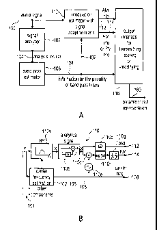
Fig. la illustrates an apparatus for converting an audio
signal 100 into a parameterized representation 180. The
apparatus comprises a signal analyzer 102 for analyzing a
portion of the audio signal to obtain an analysis result
104. The analysis result is input into a band pass
estimator 106 for estimating information on a plurality of
band pass filters for the audio signal portion based on the
signal analysis result. Thus, the information 108 on the
plurality of band-pass filters is calculated in a signal-
adaptive manner.
Specifically, the information 108 on the plurality of band-
pass filters comprises information on a filter shape. The
filter shape can include a bandwidth of a band-pass filter
CA 02867069 2015-08-24
16
and/or a center frequency of the band-pass filter for the
portion of the audio signal, and/or a spectral form of a
magnitude transfer function in a parametric form or a non-
parametric form. Illustratively, the bandwidth of a band-pass
filter is not constant over the whole frequency range, but
depends on the center frequency of the band-pass filter.
Illustratively, the dependency is so that the bandwidth
increases to higher center frequencies and decreases to lower
center frequencies. Even more illustratively, the bandwidth of
a band-pass filter is determined in a fully perceptually correct
scale, such as the bark scale, so that the bandwidth' of a band-
pass filter is always dependent on the bandwidth actually
performed by the human ear for a certain signal-adaptively
determined center frequency.
To this end, it is illustrative that the signal analyzer 102
performs a spectral analysis of a signal portion of the audio
signal and, particularly, analyses the power distribution in the
spectrum to find regions having a power concentration, since
such regions are determined by the human ear as well when
receiving and further processing sound.
The inventive apparatus according to this embodiment additionally
comprises a modulation estimator 110 for estimating an amplitude
modulation 112 or a frequency modulation 114 for each band of the
plurality of band-pass filters for the portion of the audio
signal. To this end, the modulation estimator 110 uses the
infoLmation on the plurality of band-pass filters 108 as will be
discussed later on.
The inventive apparatus according to the embodiment of Fig. la
additionally comprises an output interface 116 for transmitting,
storing or modifying the information on the amplitude modulation
112, the information of the frequency modulation 114 or the
information on the plurality of band-pass filters 108, which
may comprise filter shape information such as the values of
the center frequencies of the band-pass filters
CA 02867069 2015-08-24
17
for .this specific portion/block of the audio signal or
other information as discussed above_ The output is a
parameterized representation 180 as illustrated in Fig. is.
. 5 Fig. lb illustrates an illustrative embodiment of the
modulation estimator 110 and the signal analyzer 102 of
Fig. la and the band-pass estimator 106 of Fig. la combined
into a single unit, which is called "carrier frequency
estimation" in Fig. lb. The modulation estimator 110
illustratively comprises a band-pass filter 110a, which
provides a band-pass signal. This is input into an
analytical signal converter 110b. The output of block 110b
is useful for calculating AM information and FM
information. For calculating the AM information, the
magnitude of the analytical signal is calculated by block
110c. The output of the analytical signal block 110b is
input into a multiplier 110d, which receives, at its other
input, an oscillator signal from an oscillator 110e, which
is controlled by the actual carrier frequency fc of the
band pass 110a. Then, the phase of the multiplier output is
determined in block 1101. The instantaneous phase is
differentiated at block 110g in order to finally obtain the
FM information. =
=
Thus, the decomposition into carrier signals and their
associated modulations components is illustrated in Fig.
lb.
In the picture the signal flow for the extraction of one
component is shown. All other components are obtained in a
similar fashion. The extraction is illustratively carried out
on a block-by-block basis using a block size of N = 214 at
48 kHz sampling frequency and overlap, roughly
corresponding to a time interval of 340 ms and a stride of
85 ms. Note that other block sizes or overlap factors may
also be used. It consists of a signal adaptive band pass
filter that is centered at a local COG [12) in the signal's
DFT spectrum. The local COG candidates are estimated by
CA 02867069 2014-10-10
18
searching positive-to-negative transitions in the CogPos
function defined in (3). A post-selection procedure ensures
that the final estimated COG positions are approximately
equidistant on a perceptual scale.
nom (k, m)
CogPos(k,m) ______________________
denom(k,m)
nom(k,m)= a Ink)01;õ(iw(i)IX (k + 1, m)12) (3)
+(1- a)nom(k,m-1)
denom(k,m)= al=12(w(i)IX (k + 1, m)12)
+ (I - a)denom(k,m -1)
a=T1ee0
For every spectral coefficient index k it yields the
relative offset towards the local center of gravity in the
spectral region that is covered by a smooth sliding window
w. The width B(k) of the window follows a perceptual scale,
e.g. the Bark scale. X(k,m) is the spectral coefficient k
in time block in. Additionally, a first order recursive
temporal smoothing with time constant r is done.
Alternative center of gravity value calculating functions
are conceivable, which can be iterative or non-iterative. A
non-iterative function for example includes an adding
energy values for different portions of a band and by
comparing the results of the addition operation for the
different portions.
The local COG corresponds to the 'mean' frequency that is
perceived by a human listener due to the spectral
contribution in that frequency region. To see this
relationship, note the equivalence of COG and 'intensity
weighted average instantaneous frequency' (IWAIF) as
derived in [12]. The COG estimation window and the
transition bandwidth of the resulting filter are chosen
with regard to resolution of the human ear ('critical
bands'). Here, a bandwidth of approx. 0.5 Bark was found
empirically to be a good value for all kinds of test items
CA 02867069 2015-08-24
19
(speech, music, ambience). Additionally, this choice is
supported by the literature [13].
Subsequently, the analytic signal is obtained using the
Hilbert transform of the band pass filtered signal and
heterodyned by the estimated COG frequency. Finally the
signal is further decomposed into its amplitude envelope
and its instantaneous frequency (IF) track yielding the
desired AM and FM signals. Note that the use of band pass
signals centered at local COG positions correspond to the
'regions of influence' paradigm of a traditional phase
vocoder. Both methods preserve the temporal envelope of a
band pass signal: The first one intrinsically and the
latter one by ensuring local spectral phase coherence.
Care has to be taken that the resulting set of filters on
the one hand covers the spectrum seamlessly and on the
other hand adjacent filters do not overlap too much since
this will result in undesired beating effects after the
synthesis of (modified) components. This involves some
compromises with respect to the bandwidth of the filters
that follow a perceptual scale but, at the same time, have
to provide seamless spectral coverage. So the carrier
frequency estimation and signal adaptive filter design turn
out to be the crucial parts for the perceptual significance
of the decomposition components and thus have strong
influence on the quality of the re-synthesized signal. An
example of such a compensative segmentation is shown in
Fig. 2c.
Fig. 2a illustrates an illustrative process for converting
an audio signal into a parameterized representation as
illustrated in Fig. 2b. In a first step 120, blocks of audio
samples are formed. To this end, a window function is
illustratively used. However, the usage of a window function is
not necessary in any case. Then, in step 121, the spectral
conversion into a high frequency resolution spectrum 121 is
performed. Then, in step 122, the center-of-gravity
CA 02867069 2015-08-24
= function is calculated illustratively using equation (3). This
calculation will be performed in the signal analyzer 102
and the subsequently determined zero crossings will be the
analysis result 104 provided from the signal analyzer 102
5 of Fig. la to the band-pass estimator 106 of Fig. is.
As it is visible from equation (3), the center of gravity
function is calculated based on different bandwidths.
Specifically, the bandwidth B(k), which is used in the
10 calculation for the nominator nom(k,m) and the denominator
(k,m) in equation (3) is frequency-dependent. The frequency
index k, therefore, determines the value of B and, even
more illustratively, the value of B increases for an increasing
frequency index k. Therefore, as it becomes clear in
15 equation (3) for nom(k,m), a "window" having the window
width B in the spectral domain is centered around a certain
frequency value k, where i runs from -B(k)/2 to +B(k)/2.
This index i, which is multiplied to a window w(i) in the
20 nom term makes sure that the spectral power value X2 (where
X is a spectral amplitude) to the left of the actual
frequency value k enters into the summing operation with a
negative sign, while the squared spectral values to the
right of the frequency index k enter into the summing
operation with the positive sign. Naturally, this function
could be different, so that, for example, the upper half
enters with a negative sign and the lower half enters with
a positive sign. The function B(k) make sure that a
perceptually correct calculation of a center of gravity
takes place, and this function is illustratively determined,
for example as illustrated in Fig. 2c, where a perceptually
correct spectral segmentation is illustrated.
In an alternative implementation, the spectral values X(k)
are transformed into a logarithmic domain before
calculating the center of gravity function. Then, the value
B in the term for the nominator and the denominator in
equation (3) is independent of the (logarithmic scale)
CA 02867069 2015-08-24
21
frequency. Here, the perceptually correct dependency is
already included in the spectral values X, which are, in
this embodiment, present in the logarithmic scale.
Naturally, an equal bandwidth in a logarithmic scale
corresponds to an increasing bandwidth with respect to the
center frequency in a non-logarithmic scale.
As soon as the zero crossings and, specifically, the
positive-to-negative transitions are calculated in step
122, the post-selection procedure in step 124 is performed.
Here, the frequency values at the zero crossings are
modified based on perceptual criteria. This modification
follows several constraints, which are that the whole
spectrum illustratively is to be covered and no spectral wholes
are illustratively allowed. Furthar.thore, center frequencies of
band-pass filters are positioned at center of gravity
function zero crossings as far as possible and, illustratively
the positioning of center frequencies in the lower portion
of the spectrum is favored with respect to the positioning
in the higher portion of the spectrum. This means that the
signal adaptive spectral segmentation tries to follow
center of gravity results of the step 122 in the lower
'portion of the spectrum more closely and when, based on
this determination, the center of gravities in the higher
portion of the spectrum do not coincide with band-pass
center frequencies, this offset is accepted.
As soon as the center frequency values and the
corresponding widths of the band pass filters are
determined, the audio signal block is filtered 126 with the
filter bank having band pass filters with varying band
widths at the modified frequency values as obtained by step
124. Thus, with respect to the example in Fig. 2c, a filter
bank as illustrated in the signal-adaptive spectral
segmentation is applied by calculating filter coefficients
and setting these filter coefficients, and the filter bank
is subsequently used for filtering the portion of the audio
CA 02867069 2015-08-24
22
signal which has been used for calculating these spectral
segmentations.
This filtering is performed with illustratively a filter bank
or a time-frequency transform such as a windowed OFT,
subsequent spectral weighting and TUFT, where a single band
pass filter is illustrated at 110a and the band pass
filters for the other components 101 form the filter bank
together with the band pass filter 110a. Based on the
subband signals the AM information and the FM
information, i.e., 112, 114 are calculated in step 128 and
output together with the carrier frequency for each band
pass as the parameterized representation of the block of
audio sampling values.
Then, the calculation for one block is completed and in the
step 130, a stride or advance value is applied in the time
domain in an overlapping manner in order to obtain the next
block of audio samples as indicated by 120 in Fig. 2a.
This procedure is illustrated in Fig. 4c. The time domain
audio signal is illustrated in the upper part where
exemplarily seven portions, each portion
illustratively
comprising the same number of audio samples are
illustrated. Each block consists of N samples. The first
block 1 consists of the first four adjacent portions 1, 2,
3, and 4. The next block 2 consists of the signal portions
2, 3, 4, 5, the third block, i.e., block 3 comprises signal
portions 3, 4, 5, 6 and the fourth block, i.e., block 4
comprises subsequent signal portions 4, 5, 6 and 7 as
illustrated. In the bit stream, step 128 from Fig. 2a
generates a parameterized representation for each block,
i.e., for block 1, block 2, block 3, block 4 or a selected
part of the block, illustratively the N/2 middle portion, since
the outer portions may contain filter ringing or the roll
-off characteristic of a transform window that is
designed accordingly. Illustratively, the parameterized
representation for each block is transmitted in a bit
stream in a
CA 02867069 2015-08-24
23
=
sequential manner. In the example illustrated in the upper
plot of Fig. 4c, a 4-fold overlapping operation is formed.
_ Alternatively, a two-fold overlap could be performed as
well so that the stride value or advance value applied in
step 130 has two portions in Fig. 4c instead of one
portion. Basically, an overlap operation is not necessary
at all but it is illustrative in order to avoid blocking
artifacts and in order to illustratively allow a cross-fade -
operation from block to block, which is, in accordance with,
an illustrative embodiment of the present invention, not
performed in the time domain but which is performed in the
AM/FM domain as illustrated in Fig. 4c, and as describedi
later on with respect to Fig. 4a and 4b.
Fig. 2b illustrates a general implementation of the
specific procedure in Fig_ 2a with respect to equation (3).
This procedure in Fig. 2b is partly performed in the signal
. analyzer and the band pass estimator_ In step 132, a
portion of the audio signal is analyzed with respect to the
spectral distribution of power. Step 132 may involve a
time/frequency transform. In a step 134, the estimated
frequency values for the local power concentrations in the
spectrum (estimated in step 133) are adapted to obtain a
perceptually correct spectral segmentation such as the
spectral segmentation in Fig. 2c, having a perceptually
motivated bandwidths of the different band pass filters
and which does not have any holes in the spectrum. In
step 135, the portion of the audio signal is filtered
with the determined spectral segmentation using the
filter bank or a transform method, where an example for a
filter bank implementation is given in Fig. lb for one
channel having band pass 110a and corresponding band pass
filters for the other components 101 in Fig. lb. The
result of step 135 is a plurality of band pass signals
for the bands having an increasing bandwidth to higher
frequencies. Then, in step 136, each band pass signal is
separately processed using elements 110a to 110g in the
illustrative embodiment. However, alternatively, all other
methods for extracting an A modulation and an. F
CA 02867069 2015-08-24
24
modulation can be performed to parameterize each band pass
signal.
Subsequently, Fig. 2d will be discussed, in which an
illustrative sequence of steps for separately processing each
band pass signal is illustrated. In a step 138, a band pass
= filter is set using the calculated center frequency value
and using a band width as determined by the spectral
segmentation as obtained in step 134 of Fig. 2b. This step
uses band pass filter information and can also be used for
outputting band pass filter information to the output
interface 116 in Fig. la. In step 139, the audio signal is
filtered using the band pass filter set in step 138. In
step 140, an analytical signal of the band pass signal is
formed. Here, the true Hilbert transform or an approximated
Hilbert transform algorithm can be applied. This is
illustrated by item 110b in Fig. lb. Then, in step 141, the
Implementation of box 110c of Fig. lb is performed, i.e.,
the magnitude of the analytical signal is determined in
order to provide the AM information. Basically, the AM
information is obtained in the same resolution as the
resolution of the band pass signal at the output of block
110a. In order to compress this large amount of AM
information, any decimation or parameterization techniques
can be performed, which will be discussed later on.
In order to obtain phase or frequency information, step 142
comprises a multiplication of the analytical signal by an
oscillator signal having the center frequency of the band
pass filter. In case of a multiplication, a subsequent low
pass filtering operation is preferred to reject the high
frequency portion generated by the multiplication in step
142. When the oscillator signal is complex, then, the
filtering is not required. Step 142 results in a down mixed
analytical signal, which is processed in step 143 to
extract the instantaneous phase information as indicated by
box 110f in Fig. lb. This phase information can be output
as parametric information in addition to the AM
CA 02867069 2015-08-24
information, but it is illustrative to differentiate this
phase information in box 144 to obtain a true frequency
modulation information as illustrated in Fig. lb at 114.
Again, the phase information can be used for describing the
5 frequency/phase related fluctuations. When phase
information as parameterization information is sufficient,
then the differentiation in block 110g is not necessary.
Fig. 3a illustrates an apparatus for modifying a
10 parameterized representation of an audio signal that has,
for a time portion, band pass filter information from a
plurality of band pass filters, such as block 1 in the plot
in the middle of Fig. 4c. The band pass filter information
indicates time/varying band pass filter center frequencies
15 (carrier frequencies) of band pass filters having band
widths which depend on the band pass filters and the
frequencies of the band pass filters, and having amplitude
modulation or phase modulation or frequency modulation
information for each band pass filter for the respective
20 time portion. The apparatus for modifying comprises an
information modifier 160 which is operative to modify the
time varying center frequencies or to modify the amplitude
modulation information or the frequency modulation
information or the phase modulation information and which
25 outputs a modified parameterized representation which has
carrier frequencies for an audio signal portion, modified
AM information, modified PM information or modified FM
information.
Fig. 3h illustrates an illustrative embodiment of the information
modifier 160 in Fig. 3a. Illustratively, the AM information is
introduced into a decomposition stage for decomposing the AM
information into a coarse/fine scale structure. This decomposition
is, illustratively, a non linear decomposition such as the
decomposition as illustrated in Fig. 3c. In order to compress the
transmitted data for the AM information, only the coarse structure
is, for example, transmitted to a synthesizer. A portion of this
synthesizer
CA 02867069 2015-08-24
26
can be the adder 160e and the band pass noise source 160f.
However, these elements can also be part of the information
modifier. In the illustrative embodiment, however, a
transmission path is between block 160a and 160e, and on
this transmission channel, only a parameterized
representation of the coarse structure and, for example, an
energy value representing or derived from the fine
structure is transmitted via line 161 from an analyzer to a
synthesizer. Then, on the synthesizer side, a noise source '
160f is scaled in order to provide a band pass noise signal
for a specific band pass signal, and the noise signal has
an energy as indicated via a parameter such as the energy
value on line 161. Then, on the decoder/synthesizer side,
the noise is temporally shaped by the coarse structure,
weighted by its target energy and added to the transmitted
coarse structure in order to synthesize a signal that only
required a low bit rate for transmission due to the
artificial synthesis of the fine structure. Generally, the
noise adder 160f is for adding a (pseudo-random) noise
signal having a certain global energy value and a
predetermined temporal energy distribution. It is
controlled via transmitted side information or is fixedly
set e.g. based on an empirical figure such as fixed values
determined for each band. Alternatively it is controlled by
a local analysis in the modifier or the synthesizer, in
which the available signal is analyzed and noise adder
control values are derived. These control values illustratively
are energy-related values.
The information modifier 160 may, additionally, comprise a
constraint polynomial fit functionality 160b and/or a
transposer 160d for the carrier frequencies, which also
transposes the FM information via multiplier 160c.
Alternatively, it might also be useful to only modify the
carrier frequencies and to not modify the FM information or
the AM information or to only modify the FM information but
to not modify the AM information or the carrier frequency
information.
CA 02867069 2015-08-24
= 27
Raving the modulation components at hand, new and
interesting processing methods become feasible. An intended
advantage of the modulation decomposition presented herein
is that the proposed analysis/synthesis method implicitly
assures that the result of any modulation processing -
independent to a large extent from the exact nature of the
processing - will be perceptually smooth (free from
clicks, transient repetitions etc.). A few examples of
modulation processing are subsumed in Fig. 3b.
For sure a prominent application is the 'transposing' of an
audio signal while maintaining original playback speed:
This is easily achieved by multiplication of all carrier
components with a constant factor. Since the temporal
structure of the input signal is solely captured by the AM
signals it is unaffected by the stretching of the carrier's
spectral spacing.
If only a subset of carriers corresponding to certain
predefined frequency intervals is mapped to suitable new
values, the key mode of a piece of music can be changed
from e.g. minor to major or vice versa. To achieve this,
the carrier frequencies are quantized to MIDI numbers that
are subsequently mapped onto appropriate new MIDI numbers
(using a-priori knowledge of mode and key of the music item
to be processed). Lastly, the mapped MIDI numbers are
converted back in order to obtain the modified carrier
frequencies that are used for synthesis. Again, a dedicated
MIDI note onset/offset detection is not required since the
temporal characteristics are predominantly represented by
the unmodified AM and thus preserved.
A more advanced processing is targeting at the modification
of a signal's modulation properties: For instance it can be
desirable to modify a signal's 'roughness' 1143[151 by
modulation filtering. In the AM signal there is coarse
structure related to on- and offset of musical events etc.
CA 02867069 2014-10-10
28
and fine structure related to faster modulation frequencies
(-30-300 Hz). Since this fine structure is representing the
roughness properties of an audio signal (for carriers up to
2 kHz) [15)(16), auditory roughness can be modified by
removing the fine structure and maintaining the coarse
structure.
To decompose the envelope into coarse and fine structure,
nonlinear methods can be utilized. For example, to capture
the coarse AM one can apply a piecewise fit of a (low
order) polynomial. The fine structure (residual) is
obtained as the difference of original and coarse envelope.
The loss of AM fine structure can be perceptually
compensated for - if desired - by adding band limited
'grace' noise scaled by the energy of the residual and
temporally shaped by the coarse AM envelope.
Note that if any modifications are applied to the AM signal
it is advisable to restrict the FM signal to be slowly
varying only, since the unprocessed FM may contain sudden
peaks due to beating effects inside one band pass region
[17][18]. These peaks appear in the proximity of zero [19]
of the AM signal and are
perceptually negligible. An
example of such a peak in IF can be seen in the signal
according to formula (1) in Fig. 9 in form of a phase jump
of pi at zero locations of the Hilbert envelope. The
undesired peaks can be removed by e.g. constrained
polynomial fitting on the FM where the original AM signal
acts as weights for the desired goodness of the fit. Thus
spikes in the FM can be removed without introducing an
undesired bias.
Another application would be to remove FM from the signal.
Here one could simply set the FM to zero. Since the carrier
signals are centered at local COGs they represent the
perceptually correct local mean frequency.
CA 02867069 2015-08-24
29
Fig. 3c illustrates an example for extracting a coarse
structure from a band pass signal. Fig. 3c illustrates a
typical coarse structure for a tone produced by a certain
instrument in the upper plot. At the beginning, the
instrument is silent, then at an attack time instant, a
sharp rise of the amplitude can be seen, which is then kept
constant in a so-called sustain period. Then, the tone is
released. This is characterized by a kind of an exponential
decay that starts at the end of the sustained period. This
is the beginning of the release period, i.e., a release
time instant. The sustain period is not necessarily there
in instruments. When, for example, a guitar is considered,
it becomes clear that the tone is generated by exciting a
string and after the attack at the excitation time instant,
a release portion, which is quite long, immediately follows
which is characterized by the fact that the string
oscillation is dampened until the string comes to a
stationary state which is, then, the end of the release
time. For typical instruments, there exist typical forms or
coarse structures for such tones. In order to extract such
coarse structures from a band pass signal, it is illustrative
to perform a polynomial fit into the band pass signal,
where the polynomial fit has a general form similar to the
form in the upper plot of Fig. 3c, which can be matched by
determining the polynomial coefficients. As soon as a best
matching polynomial fit is obtained, the signal is
determined by the polynomial feed, which is the coarse
structure of the band pass signal is subtracted from the
actual band pass signal so that the fine structure is
obtained which, when the polynomial fit was good enough, is
a quite noisy signal which has a certain energy which can
be transmitted from the analyzer side to the synthesizer
side in addition to the coarse structure information which
would be the polynomial coefficients. The decomposition of
a band pass signal into its coarse structure and its fine
structure is an example for a non-linear decomposition.
Other non-linear compositions can be performed as well in
order to extract other features from the band pass signal
CA 02867069 2015-08-24
and in order to heavily reduce the data rate for
transmitting AM information in a low bit rate application.
Fig. 3d illustrates the steps in such a procedure. In a
5 step 165, the coarse structure is extracted such as by
polynomial fitting and by calculating the polynomial
parameters that are, then, the amplitude modulation
= information to be transmitted from an analyzer to a
synthesizer. In order to more efficiently perform this
10 transmission, a further quantization and encoding operation
166 of the parameters for transmission is performed. The
quantization can be uniform or non-uniform, and the
encoding operation can be any of the well-known entropy
encoding operations, such as Huffman coding, with or
15 without tables or arithmetic coding such as a context based
arithmetic coding as known from video compression.
Then, a low bit rate AM information or FM/PM information is
formed which can be transmitted over a transmission channel
20 in a very efficient manner. On a synthesizer side, a step
168 is performed for decoding and de-quantizing the
transmitted parameters. Then, in a step 169, the coarse
structure is reconstructed, for example, by actually
calculating all values defined by a polynomial that has the
25 transmitted polynomial coefficients. Additionally, it might
be useful to add grace noise per band illustratively based on
transmitted energy parameters and temporally shaped by the
coarse AM information or, alternatively, in an ultra bit
rate application, by adding (grace) noise having an
30 empirically selected energy.
Alternatively, a signal modification may include, as
discussed before, a mapping of the center frequencies to
MIDI numbers or, generally, to a musical scale and to then
transform the scale in order to, for example, transform a
piece of music which is in a major scale to a minor scale
or vice versa. In this case, most illustratively, the carrier
CA 02867069 2015-08-24
31
=
frequencies are modified. Illustratively, the AM information or ,
the PM/FM information is not modified in this case.
Alternatively, other kinds of carrier frequency
modifications can be performed such as transposing all
carrier frequencies using the same transposition factor
which may be an integer number higher than 1 or which may
be a fractional number between 1 and 0. In the latter case,
the pitch of the tones will be smaller after modification,
and in the former case, the pitch of the tones will be
. higher after modification than before the modification.
Fig_ 4a illustrates an apparatus for synthesizing a
parameterized representation of an audio signal, the
parameterized representation comprising band pass
information such as carrier frequencies or band pass center
frequencies for the band pass filters. Additional
components of the parameterized .representation are
information on an amplitude modulation, information on a
frequency modulation or information on a phase modulation
of a band pass signal.
In order to synthesize a signal, the apparatus for
synthesizing comprises an input interface 200 receiving an
unmodified or a modified parameterized representation that
. includes information for all band pass filters.
Exemplarily, Fig. 4a illustrates the synthesis modules for
a single band pass filter signal. In order to synthesis AM
information, an AM synthesizer 201 for synthesizing an AM
component based on the AM modulation is provided.
Additionally, an FM/PM synthesizer for synthesizing an
instantaneous frequency or phase information based on the
information on the carrier frequencies and the transmitted
PM or FM modulation information is provided as well. Both
elements 201, 202 are connected to an oscillator module 203
for generating an output signal, which is AM/FM/PM modulated
oscillation signal 204 for each filter bank channel.
Furthermore, a combiner 205 is provided for combining
CA 02867069 2015-08-24
32
signals from the band pass filter channels, such as signals
204 from oscillators for other band pass filter channels
and for generating an audio output signal that is based on
the signals from the band pass filter channels. Just just
adding the band pass signals in a sample wise manner in an
illustrative embodiment, generates the synthesized audio)
signal 206. However, other combination methods can be used
as well.
Fig. 4b illustrates an illustrative embodiment of the Fig. 4a
synthesizer. An illustrative implementation is based on an
overlap-add operation (OLA) in the modulation domain, i.e., in
the domain before generating the time domain band pass signal.
As illustrated in the middle plot of Fig. 4c, the input signal
which may be a bit stream, but which may also be a direct
connection to an analyzer or modifier as well, is separated
into the AM component 207a, the FM component 207b and the
carrier frequency component 207c. The AM synthesizer 201
illustratively comprises an overlap-adder 201a and,
additionally, a component bonding controller 201b which,
illustratively not only comprises block 201a but also
block 202a, which is an overlap adder within the FM
synthesizer 202. The FM synthesizer 202 additionally
comprises a frequency overlap-adder 202a, a phase
integrator 202b, a phase combiner 202c which, again, may be
implemented as a regular adder and a phase shifter 202d
which is controllable by the component binding controller
201b in order to regenerate a constant phase from block to
block so that the phase of a signal from a preceding block
is continuous with the phase of an actual block. Therefore,
one can say that the phase addition in elements 202d, 202c
corresponds to a regeneration of a constant that was lost
during the differentiation in block 110g in Fig. lb on the
analyzer side. From an information-loss perspective in the
perceptual domain, it is to be noted that this is the only
information loss, i.e., the loss of a constant portion by
the differentiation device 110g in Fig. lb. This loss is
CA 02867069 2015-08-24
=
33
recreated by adding a constant phase determined by the
component bonding device 201b in Fig. 4b, where 203a is
. an oscillator and 203b is a multiplier.
The signal is synthesized on an additive basis of all
components. For one component the processing chain is shown
in Fig. 4b. Like the analysis/ the synthesis is performed
on a block-by-block basis_ Since only the centered N/2
portion of each analysis block is used for synthesis, an
overlap factorof results. A
component bonding mechanism -
is utilized to blend AM and FM and align absolute phase for
components in spectral vicinity of their predecessors in a
previous block. Spectral vicinity is also calculated on a
bark scale basis to again reflect the sensitivity of the
human ear with respect to pitch perception.
In detail firstly the FM signal is added to the carrier
frequency and the result is passed on to the overlap-add
(OLA) stage. Then it is integrated to obtain the phase of
the component to be synthesized_ A sinusoidal oscillator is
fed by the resulting phase signal. The AM signal is
processed likewise by another OLA stage_ Finally the
oscillator's output is modulated in its amplitude by the
resulting AM signal to obtain the components' additive
contribution to the output signal.
Fig. 4c, lower block shows an illustrative implementation of
the overlap add operation in the case of SO% overlap. In
this implementation, the first part of the actually
utilized information from the current block is added to the
corresponding part that is the second part of a preceding
block. Furthermore. Fig. 4c, lower block, illustrates a
cross-fading operation where the portion of the block that
is faded out receives decreasing weights from 1 to 0 and,
at the same time, the block to be faded in receives
increasing weights from 0 to 1. These weights can already
be applied on the analyzer side and, then, only an adder.
operation on the decoder side is necessary. However,
illustratively, these weights are not applied on the encoder
CA 02867069 2015-08-24
34
side but are applied on the decoder side in a predefined
way. As discussed before, only the centered N/2 portion of
. each analysis block is used for synthesis so that an
overlap factor of 1/2 results as illustrated in Fig. 4c.
However, one could also use the complete pottier' of each
analysis block for overlap/add so that a 4-fold overlap as
illustrated in the- upper portion of Fig_ 4c is illustrated.
The described embodiment, in which the center part is used,
is illustrative, since the outer quarters include the roll-
off of the analysis window and the center quarters only
have the flat-top portion_
All other overlap ratios can be implemented as the case may
be.
Fig. 4d illustrates an illustrative sequence of steps to be
performed within the Fig. 4a/4b illustrative embodiment. In
a step 170, two adjacent blocks of AM information are
blended/cross faded. Illustratively, this cross-fading
operation is performed in the modulation parameter domain
rather than in the domain of the readily synthesized,
modulated band-pass time signal_ Thus, beating artifacts
between .the two signals to be blended are avoided compared
to the case, in which the cross fade would be performed in
the time domain and not in the modulation parameter domain.
In step 171, an absolute frequency for a certain instant is
calculated by combining the block-wise carrier frequency
for a band pass signal with the fine resolution FM
information using adder 202c. Then, in step 171, two
adjacent blocks of absolute frequency information are
blended/cross faded (172) in order to obtain a blended
instantaneous frequency at the output of block 202a. In
step 173, the result of the OLA operation 202a is
integrated as illustrated in block 202b in Fig. 4b.
Furthermore, the component_ bonding operation 201b
determines the absolute phase of a corresponding
predecessor frequency in a previous block as illustrated at
174. Based on the determined phase, the phase shifter 202d
CA 02867069 2015-08-24
of Fig. 4b adjusts the absolute phase of the signal by
addition of a suitable 4 in block 202c which is also
illustrated by step 175 in Fig. 4d. Now, the phase is ready
for phase-controlling a sinusoidal oscillator as indicated
5 in step 176. Finally, the oscillator output signal is
amplitude-modulated in step 177 using the cross faded
. amplitude information of block 170. The amplitude modulator
such as the multiplier 203b finally outputs a synthesized
band pass signal for a certain band pass channel which, due
10 to the inventive procedure according to embodiments of the
invention has a frequency band width which varies from
low to high with increasing band pass center frequency.
In the following, some spectrograms are presented that
15 demonstrate the properties of the proposed modulation
processing schemes. Fig. 7a shows the original log
spectrogram of an excerpt of an orchestral classical music
item (Vivaldi).
20 Fig. 7b to Fig. 7e show the corresponding spectrograms
after various methods of modulation processing in order of
increasingly restored modulation detail. Fig. 7b
illustrates the signal reconstruction solely from the
carriers. The white regions correspond to high spectral
25 energy and coincide with the local energy concentration in
the spectrogram of the original signal in Fig.7a. Fig. 7c
depicts the same carriers but refined by non-linearly
smoothed AM and FM. The addition of detail is clearly
visible. In Fig. 7d additionally the loss of AM detail is
30 compensated for by addition of envelope shaped 'grace'
noise which again adds more detail to the signal. Finally
the spectrogram of the synthesized signal from the
unmodified modulation components is shown in Fig. 7e.
Comparing the spectrogram in Fig. 7e to the spectrogram of
35 the original signal in Fig. 7a illustrates the very good
reproduction of the full details.
CA 02867069 2014-10-10
36
To evaluate the performance of the proposed method, a
subjective listening test was conducted. The MUSHRA [21]
type listening test was conducted using STAX high quality
electrostatic headphones. A total number of 6 listeners
participated in the test. All subjects can be considered as
experienced listeners.
The test set consisted of the items listed in Fig. 8 and
the configurations under test are subsumed in Fig.9.
The chart plot in Fig. 8 displays the outcome. Shown are
the mean results with 95% confidence intervals for each
item. The plots show the results after statistical analysis
of the test results for all listeners. The X-axis shows the
processing type and the Y-axis represents the score
according to the 100-point MUSHRA scale ranging from 0
(bad) to 100 (transparent).
From the results it can be seen that the two versions
having full AM and full or coarse FM detail score best at
approx. 80 points in the mean, but are still
distinguishable from the original. Since the confidence
intervals of both versions largely overlap, one can
conclude that the loss of FM fine detail is indeed
perceptually negligible. The version with coarse AM and FM
and added 'grace' noise scores considerably lower but in
the mean still at 60 points: this reflects the graceful
degradation property of the proposed method with increasing
omission of fine AM detail information.
Most degradation is perceived for items having strong
transient content like glockenspiel and harpsichord. This
is due to the loss of the original phase relations between
the different components across the spectrum. However, this
problem might be overcome in future versions of the
proposed synthesis method by adjusting the carrier phase at
temporal centres of gravity of the AM envelope jointly for
all components.
CA 02867069 2015-08-24
. ,
37
=
For the classical music items in the test set the observed
degradation is statistically insignificant
The analysis/synthesis method presented could be of use in
different application scenarios: For audio coding it could
serve as a building block of an enhanced perceptually
correct fine grain scalable audio coder the basic principle
of which has been published in (1]. With decreasing bit
rate less detail might be conveyed to the receiver side by
e.g. replacing the full AM envelope by a coarse one and
added 'grace' noise.
Furthermore new concepts of audio bandwidth extension (20]
are conceivable which e.g. use shifted and altered baseband
/5 components to form the high bands. Improved experiments on
human auditory properties become feasible e.g. improved
creation of chimeric sounds in order to further evaluate
the human perception of modulation structure [11].
Last but not least new and exciting artistic audio effects for
music production are within reach: either scale and key
mode of a music item can be altered by suitable processing
of the carrier signals or the psycho acoustical property of
roughness sensation can be accessed by manipulation on the
AM components.
A proposal of a system for decomposing an arbitrary audio signal
into perceptually meaningful carrier and AM/FM components has been
presented, which is intended to allow for fine grain scalability
of modulation detail modification. An appropriate re-synthesis
method has been given. Some examples of modulation processing
principles have been outlined and the resulting spectrograms of an
example audio file have been presented. A listening test has been
conducted to verify the perceptual quality of different types of
modulation processing and subsequent re-synthesis. Future
application scenarios for this promising new analysis/synthesis
method have been identified. The results
CA 02867069 2015-08-24
_ .
38
demonstrate that the proposed method provides appropriate means to
bridge the gap between parametric and waveform audio processing and
moreover may render new fascinating audio effects possible.
The described embodiments are merely illustrative for the
principles of the present invention. It is understood that
modifications and variations of the arrangements and the details
described herein will be apparent to others skilled in the art.
It is the intent, therefore, to be limited only by the scope of
the impending patent claims and not by the specific details
presented by way of description and explanation of the
embodiments herein.
Depending on certain implementation requirements of the inventive
methods according to embodiments of the invention, such inventive
methods can be implemented in hardware or in software. The
implementation can be performed using a digital storage medium, in
particular, a disc, a DVD or a CD having electronically-readable
control signals stored thereon, which co-operate with programmable
computer systems such that such inventive methods are performed.
Generally, according to its embodiments the present invention is
therefore a computer program product with a program code stored on
a machine-readable carrier, the program code being operated
for performing the inventive methods when the computer program
product runs on a computer. In other words, such inventive methods
are, therefore, a computer program having a program code for
performing at least one of the inventive methods according to
embodiments of the invention when the computer program runs on a
computer.
REFERENCES
[I] M. Vinton and L. Atlas, "A Scalable And Progressive 35 Audio
Codec," in Proc. of ICASSP 2001, pp. 3277-3280, 2001
[2] H. Dudley, "The vocoder," in Dell Labs Record, vol. 17,
pp. 122-126, 1939
CA 02867069 2014-10-10
39
[3] J. L. Flanagan and R. M. Golden, "Phase Vocoder," in
Bell System Technical Journal, vol. 45, pp. 1493-1509, 1966
[4] J. L. Flanagan, "Parametric coding of speech spectra,"
J. Acoust. Soc. Am., vol. 68 (2), pp. 412-419, 1980
[5] U. Zoelzer, DAFX: Digital Audio Effects, Wiley & Sons,
pp. 201-298, 2002
[6] H. Kawahara, "Speech representation and transformation
using adaptive interpolation of weighted spectrum: vocoder
revisited," in Proc. of ICASSP 1997, vol. 2, pp. 1303-1306,
1997
[7]A. Rao and R. Kumaresan, "On decomposing speech into
modulated components," in IEEE Trans. on Speech and Audio
Processing, vol. 8, pp. 240-254, 2000
[8] M. Christensen et al., "Multiband amplitude modulated
sinusoidal audio modelling," in IEEE Proc. of ICASSP 2004,
vol. 4, pp. 169-172, 2004
[9] K. Nie and F. Zeng, "A perception-based processing
strategy for cochlear implants and speech coding," in Proc.
of the 26th IEEE-EMBS, vol. 6, pp. 4205-4208, 2004
[10] J. Thiemann and P. Kabal, "Reconstructing Audio
Signals from Modified Non-Coherent Hilbert Envelopes," in
Proc. Interspeech (Antwerp, Belgium), pp. 534-537, 2007
[11] Z. M. Smith and B. Delgutte and A. J. Oxenham,
"Chimaeric sounds reveal dichotomies in auditory
perception," in Nature, vol. 416, pp. 87-90, 2002
[12] J. N. Anantharaman and A.K. Krishnamurthy, L.L Feth,
"Intensity weighted average of instantaneous frequency as a
CA 02867069 2014-10-10
model for frequency discrimination," in J. Acoust. Soc.
Am., vol. 94 (2), pp. 723-729, 1993
[13] 0. Ghitza, "On the upper cutoff frequency of the
5 auditory critical-band envelope detectors in the context of
speech perception," in J. Acoust. Soc. Amer., vol. 110(3),
pp. 1628-1640, 2001
[14] E. Zwicker and H. Fastl, Psychoacoustics - Facts and
10 Models, Springer, 1999
[15] E. Terhardt, "On the perception of periodic sound
fluctuations (roughness)," in Acustica, vol. 30, pp. 201-
213, 1974
[16] P. Daniel and R. Weber, "Psychoacoustical Roughness:
Implementation of an Optimized Model," in Acustica, vol.
83, pp. 113-123, 1997
[17] P. Loughlin and B. Tacer, "Comments on the
interpretation of instantaneous frequency," in IEEE Signal
Processing Lett., vol. 4, pp. 123-125, 1997.
[18] D. Wei and A. Bovik, "On the instantaneous frequencies
of multicomponent AM-FM signals," in IEEE Signal Processing
Lett., vol. 5, pp. 84-86, 1998.
[19] Q. Li and L. Atlas, "Over-modulated AM-FM
decomposition," in Proceedings of the SPIE, vol. 5559, pp.
172-183, 2004
[20] M. Dietz, L. Liljeryd, K. Kjorling and O. Kunz,
"Spectral Band Replication, a novel approach in audio
coding," in 112th AES Convention, Munich, May 2002.
[21] ITU-R Recommendation BS.1534-1, "Method for the
subjective assessment of intermediate sound quality
CA 02867069 2014-10-10
41
(MUSHRA)," International Telecommunications Union, Geneva,
Switzerland, 2001.
[22] "Sinusoidal modeling parameter estimation via a
dynamic channel vocoder model" A.S. Master, 2002 IEEE
International Conference on Acoustics, Speech and Signal
Processing.