Note: Descriptions are shown in the official language in which they were submitted.
CA 02867089 2014-09-11
WO 2013/153355
PCT/GB2013/000169
An assay label
The present invention relates to an assay label and particularly an assay
label based on a
carbon particle for use in an immunoassay.
A number of assay systems use carbon particles as the detection conjugate (or
label). One
such example is a lateral-flow strip which uses carbon particles that are
visualised by eye.
Another example is the assay system described in WO 2004/090512, which employs
a device
having a pyroelectric/piezoelectric transducer for the detection of heat
generated by
illumination of the label during the assay. Carbon particles are well-suited
to this system,
since they are strong absorbers of electromagnetic radiation at a range of
wavelengths,
including the UV, visible and infra-red parts of the spectrum. Carbon
particles are also not
particularly mass dense, so they suspend well in the sample and do not overly
sediment,
which could cause interference in an assay system using a
pyroelectric/piezoelectric
transducer.
Particulate carbon is generally considered to have an "active" surface which
can adsorb
hydrophobic materials. For example, activated charcoal is used in filters for
cooker hoods,
and carbon particles are used to purify chemical reaction mixtures. In the
latter, polymeric
and/or hydrophobic impurities are commonly removed from a reaction vessel by
adding
activated charcoal, which adsorbs the impurities. The charcoal is then removed
by filtration.
For this reason, carbon particles have been used in assays for some time, not
as a label, but
as a means of removing excess unwanted reagents. In particular, they have been
used to
remove excess radiolabelled reagents from competition immunoassays (e.g.
insulin, folate,
free T3, free T4). Such uses of carbon particles are described in US
3,442,819, US
4,028,465 and in N. Poznanski and W.J. Poznanski, Clin. Chem., 1969, 15, 908-
918. In this
technical application, a competition reaction is carried out in solution
between a radiolabelled
small molecule and an endogenous small molecule, where these compete for
binding with a
fixed amount of antibody. The small molecule fraction which does not bind to
the antibody is
then removed by adding carbon particles which have been pre-treated with
dextran (or other
macromolecules). The dextran allows small molecules to pass through and bind
to the
carbon, but not large molecules, so the carbon-dextran removes the unbound
small molecule,
but not the small molecule fraction bound to the antibody. The carbon-dextran
is then filtered
and the bound reagent is quantified by measuring the radioactivity of the
remaining solution.
These documents teach the reader that carbon particles are likely to have a
greater affinity for
hydrophobic small molecules than they do for dextran. A common method for
attaching small
molecules to colloidal labels is firstly to attach the small molecule
covalently to a larger carrier
(such as a macromolecule) and then attach the conjugate to the label, i.e. by
passive
1
CA 02867089 2014-09-11
WO 2013/153355
PCT/GB2013/000169
adsorption. However, if one prepares a covalent conjugate of dextran with a
hydrophobic
small molecule, one might expect binding of the conjugate to the carbon by
attachment of the
small molecule to the carbon. This is, therefore, unlikely to be a good way to
prepare carbon
conjugates of small molecules, because the small molecules would not be
accessible.
There are examples in the literature describing the use of antibody-coated
carbon particles as
assay labels. For example, US 4,760,030 describes the passive adsorption of
antibodies
onto carbon particles. However, the particles in US 4,760,030 require
stabilisation with amino
acids in order to coat the antibody onto the particle. There is also some
reference to the India-
ink assay (also known as the Geck assay), which is an agglutination assay
where carbon
particles and antibody are mixed simultaneously, and agglutination takes place
in the
presence of an analyte. Again, stabilisers are required to form the carbon
colloid.
US 5,252,496, US 5,559,041 and US 6,506,612 also describe antibody binding to
carbon
particles. These patents use Vulcan XC72 carbon particles, which must be
stabilised in order
to form a colloid in. water. These patents describe the use of 2% dextran
9,400 as the
stabilising agent. Example 7 in column 13 of US 5,252,496 describes
immobilisation of a
monoclonal antibody to the carbon. In summary, the carbon particles are
homogenised in
buffer with 2% dextran, the dextran being described as a "suspending
adjuvant". After 2 h
fluorescein isothiocyanate (FITC) is added and the suspension is incubated for
12 h, then
washed several times before antibody being added, followed by further washing,
and storage
of the colloid in an appropriate storage buffer.
It is not entirely clear what the mechanism is by which the antibody is
attached to the particle.
Firstly, FITC has only one chemically reactive functional group and so is not
a cross-linking
agent, so there is no expected mechanism by which FITC could covalently link
the antibody to
the dextran. Secondly, isothiocyanates are normally used for reaction with
amines (to yield
thioureas), but can also react with alcohols (to give thiocarbamates) or be
hydrolysed to
amines. Given an incubation time of 12 h, the FITC will either react with the
hydroxyl groups
on the dextran or be hydrolysed. It appears that the proposed mechanism of
binding is that
the FITC somehow binds to the surface of the dextran carbon. Fluorescein would
not be
expected to bind to dextran, so this implies that the FITC is bound (passively
adsorbed) onto
the surface of the carbon itself. The isothiocyanate group would not then be
available for
binding to lysine groups (amines) on antibodies.
US 6,506,612 also describes methods whereby a binding agent is ccivalently
bound through a
cross-linker to a primary passively adsorbed layer on a carbon particle
surface. Lines 35-60
of column 8 describe such covalent linking, where the passively adsorbed layer
is always a
protein. Thus, US6,506,612 teaches that dextrans can be used initially to
stabilise carbon
colloids, but that they will ultimately be displaced by either small molecules
(such as FITC) or
2
CA 02867089 2014-09-11
WO 2013/153355
PCT/GB2013/000169
by protein molecules (such as BSA, avidin or antibodies), which will bind more
strongly to the
carbon than will the dextran. US 6,506,612 also describes a method for pre-
treating an
antibody with FITC before coating onto the carbon, the likely effect here is
that adding FITC
groups to the antibody makes it more hydrophobic and thus bind more strongly
to the carbon.
US 5,529,901 and US 5,641,689 describe a method for selecting a type of carbon
particle
(S84 from Degussa) that will form a colloid in water without the addition of
stabilising agents,
such as dextran, PEG, glycine etc. They also describe the selection of SB4
(and similar
particles) for the direct conjugation of a binding component (e.g. an
antibody) which binds to
the analyte. These patents thus teach away from the use of dextran as a
stabiliser. In fact,
they describe the use of dextran to stabilise the particle as an unnecessary
step, which can
be removed by specifically using these particles.
The carbon particles that have typically been used in assays are conjugated
using a passive
adsorption method, see US 5,529,901 and US 5,641,689. This method is specific
for certain
types of carbon, in particular Spezial Schwartz 4 (SB4) from Degussa/Evonik
(amorphous
carbon particles .having an average size of 100-200 nm), which form a stable
colloid in water
in the absence of any stabilisers. Alternatively, most other carbon particles
require a
stabiliser, such as a detergent or a macromolecule (e.g. dextran, PEG, glycine
etc). The
passive adsorption method is suitable for most antibody-based assays, but it
should be noted
that the majority of antibodies lose activity during passive adsorption,
because the antibody is
denatured as it binds to the surface (this is similar to what happens when
antibody is
passively adsorbed to the surface of microtitre plates). A useful rule-of-
thumb is that
approximately 10% of passively adsorbed antibody will be active, the remaining
90% being
inactive, largely due to denaturation of the antibody.
For assays that require very high sensitivity, it is beneficial to have a
higher loading of
antibody on the carbon particles, which would require an alternative route to
passive
adsorption. Higher loading of antibody drives the thermodynamic equilibrium of
the antibody-
antigen interaction. Higher antibody loading per particle is preferred, rather
than simply
adding more particles, so that the system is not overloaded with particles
(leading to non-
specific binding). Additionally, passively adsorbed antibody is in close
proximity to the surface
of the carbon, which can make the antibody quite sterically hindered. Having
antibody farther
from the surface of the carbon may have benefits, in terms of reducing steric
hindrance.
Finally, passive adsorption of antibody onto the carbon leads to denaturation
of the antibody,
which can potentially promote non-specific binding.
In immunometric, (also known as sandwich or reagent-excess) immunoassays, as
described
in WO 2004/090512, an antibody (or similar reagent) is located on the sensor
and another
3
CA 02867089 2014-09-11
WO 2013/153355
PCT/GB2013/000169
antibody is on the carbon particles. The carbon particles then bind to the
sensor in the
presence of analyte being detected. Both antibodies are present in a large
excess.
In a competition assay, there is either (a) an antibody on the carbon
particles and an
analogue of the analyte (i.e. a small molecule) on the sensor or (b) an
analogue (i.e. a small
molecule) on the carbon particles and an antibody on the sensor. Binding takes
place in
absence of analyte, and is perturbed (reduced) in the presence of analyte.
The term "small molecule" is a term of the art in the field of immunoassays
which is used to =
distinguish between molecules which can be measured in sandwich assays and
those that
cannot. To be measured in a sandwich assay, a molecule must be sufficiently
large to have
two or more distinguishable epitopes (antibody binding sites), so that two
antibodies can bind
to the molecule simultaneously, so that the molecule can be sandwiched between
a capture
antibody and a reporter (or labelled) antibody. If the molecule cannot form a
sandwich, it falls
into the class of "small" molecules. The molecular weight cut off is about
2,000-5,000.
When carrying out competition assays there is an additional requirement to
have greater
control over the levels of the various components in the system. For antibody
bound to
carbon, it is more difficult to control the amount of active antibody when
using passive
adsorption. In the alternative format for competition assays, it is the small
molecule analogue
which must be bound to the surface of the carbon particle. This is generally
not possible with
small molecules; either they will not adsorb to a surface because they are too
small or, if they
do adsorb to a surface, they are no longer recognised by antibodies. Small
molecules are
therefore generally conjugated to larger carriers, such as proteins, and the
carrier then binds
to the surface of interest, e.g. the carbon particle.
However, it has now been found that it is difficult to prepare small molecule-
carbon
conjugates through the traditional route of covalently attaching them to
protein molecules (e.g.
a2-macroglobulin, apoferritin, 3-galactosidase, 3-amylase, collagen (ovine),
concanavalin A,
" 30 keyhole limpet hemocyanin, myosin, urease, human thyroglobulin,
porcine thyroglobulin and
bovine thyroglobulin) and subsequently binding these proteins to the surface
of the carbon
particles. This may be because the small molecules are particularly
hydrophobic (e.g.
steroids, fluorescein, immunosuppressants). This may make the protein-small
molecule
conjugates too hydrophobic for coating onto carbon particles. The materials
are either "sticky"
(they give too much non-specific binding) or unstable over time in solution.
Thus, there is a requirement for an improved method for conjugating antibodies
and small
molecules, as well as other potential binding agents, e.g. nucleic acids, to
the surface of
carbon particles in order to increase loading, control loading, reduce steric
hindrance and
4
CA 02867089 2014-09-11
WO 2013/153355
PCT/GB2013/000169
improve stability, thereby improving the assay performance by lowering assay
sensitivity and
improving precision.
Accordingly, the present invention provides an assay label comprising an
amorphous carbon
particle, a functionalised dextran polymer attached to the surface of the
carbon particle and a
first member of a complementary binding pair covalently bonded to the
functionalised dextran
polymer.
Thus, the present invention provides a conjugated carbon particle employing
dextran to attach
the molecule of interest to the carbon particle.
The present invention will now be described with reference to the drawings, in
which:
Fig. 1 shows a schematic representation of the chemical sensing device of WO
2004/090512
which is used with the present invention;
Fig. 2 shows a cartridge according to the present invention;
Fig. 3 shows a plot of carbon binding capacity assays using carbon conjugates
1 and 2;
Fig. 4 shows a graph of troponin I assays using carbon conjugates 1 and 2;
Fig. 5 shows a graph of BSA-dig(en)-FITC carbon assays over 29 days;
Fig. 6 shows a graph of reduction in chamber 3 binding of BSA-dig(en)-FITC
carbon
conjugate;
Fig. 7 shows a graph of chamber 3 binding after washing of BSA-dig(en)-FITC
carbon
conjugate;
Fig. 8 shows a graph of dextran-FITC-digoxin assays over 29 days; and
Fig. 9 shows a graph of chamber 3 binding of dextran-dig(en)-FITC conjugates
over 29 days.
The assay label of the present invention is based on an amorphous *carbon
particle. Such
particles are well known in the art and are also referred to as Carbon Black,
Lamp Black,
Furnace Black or thermal black). They are amorphous particles produced by the
incomplete
combustion of gaseous or liquid hydrocarbons. The CAS number for carbon black
is 1333-86-
4.
The size of the carbon particles will depend on the nature of the assay, but
they typically have
a particle size of 25-250 nm. Particle sizes for the carbon particles of the
present invention
represent the diameter of the particle at its widest point and may be measured
by dynamic
light scattering.
Amorphous carbon particles generally have a porous structure. The carbon
particle used in
the present invention preferably has a density of 0.8 to 3 g/mL.
5
CA 02867089 2014-09-11
WO 2013/153355
PCT/GB2013/000169
The carbon particles of the present invention form stable colloids on
suspension in an
aqueous medium. Depending on the hydrophobicity of the carbon particles (some
have more
surface hydroxyl groups than other), some carbon particles will form a stable
colloid in water
and others require the presence of a stabiliser. The present invention
preferably uses carbon
particles which form a stable colloid in water without the presence of a
stabiliser (indeed,
without the presence of any other substance). A simple test may be applied to
determine
whether or not a stable colloid is formed: suspend 1% w/v of the amorphous
carbon particles
in 1 mL of demineralised water and sonicate for 30 s to form a colloid;
measure the optical
density of the colloid using a visible spectrometer; a stable colloid will
show no change ( t%)
in optical density over 1 h.
The assay label also incorporates a functionalised dextran polymer attached to
the surface of
the carbon particle.
=
Dextran is a polymer of glucose and is composed of repeating units of a-D-
glucose-linked
glucan (typically 95%) and 1,3-glucose residues as branches (typically 5%).
Dextran is not
subject to enzymatic degradation, unlike most other polysaccharides.
The polymer used in the present invention is a functionalised dextran, meaning
that it
contains additional functional groups to those otherwise present in dextran
which can be used
to form covalent bonds. Examples of functional groups include an amino group,
a sulfate
group, a ketone, an aldehyde, a carboxylic acid, a sulfonic acid, an activated
carboxylic/sulfonic acid (such as an acid chloride or activated ester) and a
thiol group. Some
specific examples of commercially available functionalised dextrans are
aminodextran,
dextran sulfate, diethyl aminoethyl dextran and carbon/methyl dextran. A
synthesis of
aminodextrans is described in more detail in US 5,776,706. The functionalised
dextran is
preferably an aminodextran.
The functionalised dextran polymer of the present invention typically has a
number average
molecular weight of 3-2,000 KDa, preferably 5-100 KDa and most preferably 7-15
KDa. The
molecular weight can be measured by gel permeation chromatography using
commercially
available dextran standards of known molecular weight (e.g. from Sigma
Aldrich).
The functionalised dextran is attached to the carbon particle by non-covalent
interactions.
Preferably, the functionalised dextran is passively adsorbed onto the surface
of the carbon
particle. Without wishing to be bound by theory, it is believed that the
dextran is adsorbed
into pores present on the surface of the carbon particle thereby displacing
water molecules
within the pores. The driving force for the reaction is probably entropic on
account of the
release of the bound water molecules.
6
CA 02867089 2014-09-11
WO 2013/153355
PCT/GB2013/000169
The assay label also includes a first member of a complementary binding pair
covalently
bonded to the functionalised dextran.
=
In order to function in an assay, the label must contain part of a
complementary binding pair.
As previously explained, in an immunometric (also known as a sandwich or
reagent-excess)
immunoassay, one antibody raised to the analyte is located on the sensor and
another
antibody to the analyte is located on the carbon particles. The carbon
particles then bind to
the sensor in the presence of the analyte being detected. Analogous assays are
possible with
other macromolecules, such as proteins or nucleic acids. In this case, the
first member of the
complementary binding pair is a macromolecule selected from an antibody, a
protein or a
nucleic acid and the second member of the complementary binding pair is the
analyte.
= In a competition assay, there is either (a) an antibody on the carbon
particles and an
analogue of the analyte (i.e. a small molecule) on the sensor or (b) an
analogue (i.e. a small
molecule) on the carbon particles and an antibody on the sensor. Binding takes
place in
absence of analyte, and is perturbed (reduced) in the presence of analyte. In
this case, the
first member of the complementary binding pair may be a small molecule and the
second
member of the complementary binding pair is the antibody raised to the small
molecule.
Examples of the small molecule are therapeutic drugs (e.g. carbamazepine,
cyclosporine,
digoxin, theophylline and gentamycin), drugs of abuse (e.g. opiates, cocaine
and
amphetamine), vitamins (e.g. vitamin D, vitamin B12 and folate) and hormones
(T3, T4,
cortisol, progesterone, estradiol and testosterone).
The assay label of the present invention may be prepared by pre-treating the
dextran polymer
to form a dextran-small molecule conjugate. This conjugate can then be
attached to the
carbon particles to generate a stable conjugate. More than one small molecule
can be
attached to the dextran, so that the particle can be used in assays with
controls or in multiplex
assays.
The assay label of the present invention may also be prepared by attaching the
dextran
polymer to the carbon particles and separately, pre-treating an antibody, a
protein or a nucleic
acid with a reagent which will covalently bind to the functional groups on the
dextran-coated
particles. An example is to use aminodextran, which is reacted to add
maleimide groups onto
the surface of the dextran. The maleimido dextran is then coated onto the
carbon particles.
The antibody is introduced via a masked thiol, which can be unmasked to react
with the
maleimide group on the dextran. Masked thiols can be introduced by reaction
with S-acetyl
thioglycolic acid N-succinimide (SATA). In a preferred embodiment, the assay
label further
comprises a linker between the functionalised dextran and the complementary
binding
partner. For example, the maleimide groups can be introduced onto the dextran
by addition
of a heterobifunctional reagent, such as succinimidyl 4-(N-ma)eimidomethyl)
cyclohexane-1-
7
CA 02867089 2014-09-11
WO 2013/153355
PCT/GB2013/000169
carboxylate (SMCC), or by analogues of SMCC, where the cyclohexane spacer is
replaced by
alternate spacers of longer length, such as polyalkylene glycol spacers.
Following coupling of
the SATA-activated antibody to the maleimido dextran carbon, it is
advantageous to introduce
a quench step to deactivate unreacted maleimide and thiol groups, usually by
adding a
maleimide quencher (e.g. mercaptoethanol) first, followed by a thiol quencher
(e.g. N-ethyl
maleimide, or a polyalky(ene maleimide). These quenching reagents can then be
removed by
centrifugation and washing of the carbon colloid.
A useful guide for the sizes of the first member of the complementary binding
pair are: the
small molecule preferably has a molecular weight of 5,000 or less and the
macromolecule
(e.g. antibody, protein or nucleic acid) has a molecular weight above 5,0000,
e.g. from 5,001-
1,000,000.
An advantage of providing a linker is that it allows the macromolecule, e.g.
the antibody,
protein or nucleic acid, to form the correct tertiary structure by preventing
steric interaction
with the carbon particle and by permitting full solvation of the antibody,
protein or nucleic acid.
It has been found that this improves the signal:noise ratio by reducing non-
specific binding in
the assay. A preferred linker is polyethylene glycol, e.g. PEG12.
Accordingly, the present invention also provides a method for preparing an
assay label
comprising the following steps:
(i) providing an amorphous carbon particle, a functionalised dextran polymer
and a first
member of a complementary binding pair;
(ii) attaching the functionalised dextran polymer to the amorphous carbon
particle;
(iii) reacting the functionalised dextran polymer with the first member of the
complementary
binding pair to form a covalent bond between the functional groups on the
functionalised
dextran polymer and the first member of the complementary binding pair,
wherein steps (ii) and (iii) may be performed in either order, but follow step
(i).
Preferably, the method further comprises reacting the functionalised dextran
polymer with a
bifunctional molecule prior to reaction with the first member of the
complementary binding pair
to form a linker between the functionalised dextran and the first member of
the
complementary binding pair. Other preferred features of the assay label
described herein
apply equally to this method.
The assay label of the present invention finds general applicability in the
field of assays.
However, the label is preferably used in the device described with reference
to WO
2004/090512. Accordingly, the present invention also provides a device for
performing an
assay comprising:
the assay label as described herein;
8
CA 02867089 2014-09-11
WO 2013/153355
PCT/GB2013/000169
a radiation source adapted to generate a series of pulses of electromagnetic
radiation at a
wavelength such that the absorption of the radiation by the label generates
energy by non-
radiative decay;
a sample chamber containing a transducer having a pyroelectric or
piezoelectric element and
electrodes which is capable of transducing energy generated by non-radiative
decay into an
electrical signal; and
a detector which is capable of detecting the electrical signal generated by
the transducer.
Fig. 1 shows a device 1 for use in accordance with the present invention which
relies on heat
generation in a particle 2 (herein, the carbon particle of the assay label) on
irradiation of the
particle 2 with electromagnetic radiation (the particle is shown above the
transducer surface).
For the sake of simplicity, only the particle is shown in Fig. 1 (the
remaining components of
the device will be described in further detail hereinbelow). Fig. 1 shows the
device 1 in the
presence of a particle 2. The device 1 comprises a pyroelectric or
piezoelectric transducer 3
having electrode coatings 4,5. The transducer 3 is preferably a poled
polyvinylidene fluoride
film or a VDF-trifluoroethylene copolymer film. The electrode coatings 4,5 are
preferably
transparent and most preferably formed from indium tin oxide, although any
transparent or
semi-transparent electrode material would suffice, e.g. PEDOT (poly(3,4-
ethylenedioxythiophene)). The electrodes preferably have a thickness of about
35 nm,
although almost any thickness is possible from a lower limit of 1 nm below
which the electrical
conductivity is too low and an upper limit of 100 rim above which the optical
transmission is
too low (it should not be less than 80%T). In a particularly preferred
embodiment, the
transducer is an indium tin oxide-coated polyvinylidene fluoride film. An
additional layer may
be applied to the transducer 3, such as a parylene polymer layer, for passive
adsorption of
reagents to the sensor. A preferred embodiment is where the parylene layer is
subsequently
coated in a polymerised streptavidin layer.
=
The particle 2 is shown proximal to the transducer 3. An inherent feature of
the carbon
particles used in the present invention is that the particle 2 generates heat
when irradiated by
a source of electromagnetic radiation (typically termed "light") 6, preferably
visible light. The
light source may be, for example, an LED. The light source 6 illuminates the
particle 2 with
light of the appropriate wavelength. Although not wishing to be bound by
theory, it is believed
that the particle 2 absorbs the light to generate an excited state which then
undergoes non-
radiative decay thereby generating energy, indicated by the curved lines in
Fig. 1. This
energy is primarily in the form of heat (i.e. thermal motion in the
environment) although other
forms of energy, principally a shock wave, may also be generated. The energy
is, however,
detected by the transducer and converted into an electrical signal. The device
is calibrated
for the particular particle being measured and hence the precise form of the
energy generated
by the non-radiative decay does not need to be determined. Unless otherwise
specified the
term "heat" is used herein to mean the energy generated by non-radiative
decay. The light
9
CA 02867089 2014-09-11
WO 2013/153355
PCT/GB2013/000169
source 6 is positioned so as to illuminate the particle 2. Preferably, the
light source 6 is
positioned opposite the transducer 3 and electrodes 4,5 and the particle 2 is
illuminated
through the transducer 3 and electrodes 4,5. The light source may be an
internal light source
within the transducer in which the light source is a guided wave system. The
wave guide may
be the transducer itself or the wave guide may be an additional layer attached
to the
transducer. The wavelength of illumination depends on the precise nature of
the particle
used.
The energy generated by the particle 2 is detected by the transducer 3 and
converted into an .
electrical signal. The electrical signal is detected by a detector 7. The
light source 6 and the
detector 7 are both under the control of the controller 8. The light source 6
generates a series
of pulses of light which is termed "chopped light". In principle, a single
flash of light, i.e. one
pulse of electromagnetic radiation, would suffice to generate a signal from
the transducer 3.
However, in order to obtain a reproducible signal, a plurality of flashes of
light are used which
in practice requires chopped light. The frequency at which the pulses of
electromagnetic
radiation are applied may be varied. At the lower limit, the time delay
between the pulses
must be sufficient for the time delay between each pulse and the generation of
an electrical
signal to be determined. At the upper limit, the time delay between each pulse
must not be so
large that the period taken to record the data becomes unreasonably extended.
Preferably,
the frequency of the pulses is from 1-50 Hz, more preferably 1-10 Hz and most
preferably 2
Hz. This corresponds to a time delay between pulses of 20-1,000 ms, 100-1,000
ms and 500
ms, respectively. In addition, the so-called "mark-space" ratio, i.e. the
ratio of on signal to off
signal is preferably one although other ratios may be used without deleterious
effect. There
are some benefits to using a shorter on pulse with a longer off signal, in
order to allow the
system to approach thermal equilibrium before the next pulse perturbs the
system. Sources
of electromagnetic radiation which produce chopped light with different
frequencies of
chopping or different mark-space ratios are known in the art. The detector 7
determines the
time delay between each pulse of light from light source 6 and the
corresponding electrical
signal detected by detector 7 from transducer 3. This time delay is a function
of the distance,
d. When particles are bound directly to the surface, the signal is preferably
measured from 2-
7 ms. For measuring particles through the depth of the chamber, longer time
delays are used,
e.g. 10-50 ms. The system can also be configured to measure the peak maximum
in the
signal, the time delay of which can change throughout the measurement process.
Any method for determining the time delay between each pulse of light and the
corresponding
electrical signal which provides reproducible results may be used.
It should be noted that the particle 2 may be separated from the transducer
surface and that a
signal may still be detected. Moreover, not only is the signal detectable
through an
intervening medium, but that different distances, d, may be distinguished
(this has been
CA 02867089 2014-09-11
WO 2013/153355
PCT/GB2013/000169
termed "depth profiling") and that the intensity of the signal received is
proportional to the
concentration of the particle 2 at the particular distance, d, from the
surface of the transducer
3. Moreover, it was found that the nature of the medium itself influences the
time delay and
the magnitude of the signal at a given time delay.
The purpose of the particle is to absorb the electromagnetic radiation
generated by the
radiation source to generate energy by non-radiative decay. The radiative
decay is then
converted to an electrical signal by the transducer. The wavelength of the
electromagnetic
radiation is such that the absorption of the radiation by the particles
generates energy by non-
radiative decay. The wavelength of the radiation is preferably 300-1,000 nm.
Red blood cells are present in a sample of blood, i.e. (unseparated) whole
blood. These cells
tend to sediment over time in a static system such as a test tube or
container, since they are
denser than the surrounding plasma in which they are dispersed. The system
described in
WO 2004/090512 is normally set up to minimise the signal from the red blood
cells, by using
a wavelength of light at which the signal from red blood cells is minimised
(around 690 nm),
and also by measuring the signal a few milliseconds after the light pulse,
thus confining the
output to heat generated in close proximity to the transducer.
The sample will typically be in the order of microlitres (e.g. 1-100 p.1_,
preferably 1-30 IA). In
order to hold a fluid sample, the transducer is preferably located in a
chamber, the chamber
having one or more side walls, an upper surface and a lower surface.
Accordingly, the
transducer is preferably located within a chamber for holding the sample in
contact with the
transducer. Preferably, the transducer is integral with the chamber, i.e. it
forms one of the
side walls, or upper or lower surface which define the chamber. In a preferred
embodiment,
the chamber has an upper surface and a lower surface and the transducer forms
the upper
surface. The sample may simply be retained by surface tension forces, for
example, inside a
capillary channel. The depth of the chamber is typically 50 pm to 1 cm,
preferably 150-250
pm.
The device of the present invention may contain a plurality of chambers,
preferably in fluid
communication. The device preferably further contains an elongate sample
collection
passage having a sample collection end which is contact with the outside of
the device and a
sample delivery end which is in fluid communication with the sample
chamber(s), as shown in
the core 21 in Fig. 2. See WO 2011/027147 for further details.
In a preferred embodiment, the device further comprises an elongate sample
collection
passage having open ends and arranged to draw the fluid into the passage by
capillary
action, wherein the passage has a collection end and a delivery end and the
delivery end is in
fluid communication with the sample chamber. The passage may be provided along
a first
11
CA 02867089 2014-09-11
WO 2013/153355
PCT/GB2013/000169
portion of its length with a region coated with an anticoagulant. This
arrangement allows the
sample to contact the anticoagulant to prevent clotting in the collection
passage.
The device may take the form of a separate reader and cartridge, or an
integrated device. In
the former, the device is formed of a reader and a cartridge, in which the
cartridge is
releasably engageable with the reader, and in which the reader incorporates
the radiation
source.and the detector, and the cartridge incorporates the transducer and the
chamber. The
reader is preferably a portable reader. The cartridge is preferably a
disposable cartridge.
The present invention will now be described with reference to the following
examples which
are not intended to be limiting.
Examples
Example 1
PVDF film sensor
A poled piezo/pyroelectric polyvinylidene fluoride (PVDF) bimorph film, coated
in indium tin
oxide was used as the sensing device in the following examples. The indium tin
oxide
surface was coated with a layer of parylene (of approximate thickness 1
micron) by a vapour
phase gas deposition process. This method involved the sublimation and
subsequent
pyrolysis of a paracyclophane precursor, followed by a free-radical
polymerisation on the
surface. See WO 2009/141637 for further details. The resulting film was then
coated in
polystreptavidin solution (200 pg/mL in PBS ¨ 10 mmol/L phosphate buffer
containing 2.7
mmol/L KCI, 137 mmol/L NaCI and 0.05% Tween) by incubation at room temperature
overnight. Polystreptavidin was prepared as described by Tischer et al -(US
5,061,640). The
polystreptavidin provides a universal binding sensor to which other molecules
can be
attached through the high affinity biotin-streptavidin reaction.
Example 2
Preparation of the cartridge
As shown in Fig. 2, a cartridge 14 was fabricated to perform the measurement.
The cartridge
14 was fabricated from a piezo/pyrofilm 15 supported on a stiffener 16. A
pressure sensitive
adhesive-coated polyester film 17 die-cut to form three sample chambers 18 was
applied to
the surface. Provision was made to allow for electrical connections to the top
and bottom
surfaces of the piezo/pyrofilm 15 in order to detect the charge generated. The
cartridge 14
12
CA 02867089 2014-09-11
WO 2013/153355
PCT/GB2013/000169
was then formed by sandwiching the above components between a top cover 19, to
which a
label 20 was applied, and a core 21, seal 22 and bottom cover 23.
Measurements were carried out by charging the sample chambers with the sample.
The
piezo/pyrofilm 15 was irradiated through the holes in the top cover 19 with
chopped LED light
sequentially with LEDs. For each LED pulse, a voltage is measured across the
piezo/pyrofilm
using an amplifier and analogue to digital (ADC) converter. The time-resolved
ADC signal
is plotted over time.
10 Examples 3-13
In the examples that follow, assays are carried out using positive and
negative controls to
improve the accuracy and precision of the measurement. Of the two controls,
one defines the
maximum binding rate expected under diffusion control and one defines the
minimum signal
15 expected in the absence of signal (normally slightly negative owing to
particle sedimentation).
The signal output is defined ratiometrically by these two controls.
Example 3
Preparation of a carbon anti-cTnI colloid by passive adsorption (carbon
conjugate 1)
400 pg of anti-cardiac troponin I mouse monoclonal antibody clone 560
(HytestõFinland) was
prepared in 2 mL of 10 mM potassium phosphate buffer, pH 7.2. To this was
added 1 mL of a
0.2% w/v suspension of SB4 carbon particles (Degussa) in water. The mixture
was left stirring
at R/T for 2 h, then diluted by addition of. 6 mL of 10 mM potassium phosphate
buffer
containing 4.5% sucrose, 0.15% BSA and 0.075% PEG 20k (wash and storage
buffer). This
solution was then purified by three cycles of centrifugation, pelleting,
washing, sonication and
re-suspension in the storage buffer. Finally, 4.5 pL of Proclin 950
preservative was added and
the solution was stored at 4 C.
Exam_ple 4
Preparation of a carbon dextran anti-cTnI colloid by primary reaction with a
dextran reagent
followed by covalent attachment of anti cTnI antibody (carbon conjugate 2)
10 KDa aminodextran (lnvitrogen) was dissolved at 5 mg/mL in 0.1 M phosphate
pH 7.5
buffer, and 11.6 mL of this solution was incubated for 60 mins at 20 C with
3300 pL of a 30
mg/mL solution (in DMSO) of N-hydroxysuccinimide-PEG12-maleimide (Thermo
Fisher),
equivalent to a 20:1 molar excess over aminodextran. After 60 mins the
reaction was
quenched with glycine (86.73 mg) and then purified on a Sephadex G50 column,
eluting with
13
CA 02867089 2014-09-11
WO 2013/153355
PCT/GB2013/000169
0.1 M phosphate pH 7.5 buffer. The product peak was analysed with the phenol
sulfuric acid
assay to determine the concentration as 1.776 mg/mL. The aminodextran
maleimide was
stored at -80 C until required.
100 mg of SB4 carbon particles (Degussa) in water (50 mL) were sonicated for
0.5 h. From
the resulting suspension 1.667 mL of carbon colloid was mixed with
aminodextran-maleimide
= solution (2.252 mL) and 0.1 M phosphate pH 7.5 buffer (8.859 mL). The
mixture was
sonicated for 30 s then roller mixed for 90 mins. The mixture then was
centrifuged and
pelleted for 15 mins and the supernatant was discarded. The mixture was
resolubilised by
sonication in 0.01 M phosphate buffer pH 7.2 (10 mL) for 30 s and the
suspension was again
spun down. A total of three wash cycles were carried out.
In parallel, 11.66 mg of anti-troponin antibody, clone 560 (HyTest) was
desalted into
phosphate buffer using a single PD-10 Sephadex G25M disposable column and then
activated with 5 equivalents of N-succinimidyl-S-acetyl thioacetate (SATA)
(Thermo-Fisher)
(90 pL of a 1 mg/mL solution in DMSO) at 20 C for 1 h, then deprotected using
hydroxylamine
buffer (315 pL) for 15 min. The thiolated antibody was purified on 2 PD-10
Sephadex G25M
disposable columns into 0.1 M phosphate pH 7.5 buffer giving a solution
containing 1.76
mg/mL of antibody. The thiol incorporation level was measured as 1.9 thiols
per antibody
using the ElIman's assay.
After the final wash cycle of the carbon coated in aminodextran maleimide, the
supernatant
was discarded and the thiolated antibody (10 mg, 5.682 mL) was added along
with 4.318 mL
of 0.1 M phosphate buffer pH 7.5. The mixture was resolubilised by sonication
for 30 s then
=
the reaction was roller-mixed for 1 h 45 mins before being quenched with 2-
mercaptoethanol
(200 pL, 1mg/mL in water) for 15 mins, then quenched with PEG12-maleimide
(Thermo
Fisher) (180 pL, 10mg/mL) for a further 15 mins. The mixture was then spun
down as before
and underwent a further three wash cycles before a final resolubilisation in
0.01 M phosphate
+ 01% BSA + 3% sucrose + 0.05% PEG 20K pH 7.2 buffer (375 pL) with 60 s of
sonication.
Similarly, a carbon conjugate was prepared under exactly the same conditions
as above,
except that the antibody was not activated with SATA. All preparation and wash
steps were
carried out in a similar manner.
Example 5
Comparison of the binding capacities of two different carbon anti-cTn1
colloids
The anti-cTnI carbon conjugates from Examples 3 and 4 were diluted into
solutions of cardiac
troponin I in phosphate buffered saline plus 0.5% bovine serum albumin. The
final
14
CA 02867089 2014-09-11
WO 2013/153355
PCT/GB2013/000169
concentration of troponin was 50 ng/mL and the final concentration of carbon
solids ranged
from 0.000039% w/v to 0.0035% w/v. A control was also run with no carbon
conjugate added.
Total volume per reaction was 500 pL. The carbon solids concentration was
checked by
measuring the optical density of the solution at 450 nm and comparing against
a standard
curve prepared with SB4 carbon suspension in water. After incubation for 30
mins, the carbon
solids were removed from each reaction mixture by centrifugation. 50 pL of
each mixture was
then diluted into 450 pL of troponin-free serum and the concentration of
unbound troponin in
each sample was measured on an Abbott Architect Clinical Immunoassay analyser.
The
quantity of bound troponin at each concentration of carbon solids was
calculated by
subtraction, this was then plotted and the total carbon conjugate required to
bind 50% of the
troponin for each of the two conjugates was interpolated from the data (shown
in Fig. 3).
The concentration of bound troponin is governed by the equilibrium equation:
= ___________
fAb 4 Agj
tAbi [Agj
where [Ab*Ag] is the concentration of troponin-antibody complex, [Ag] is the
concentration of
free troponin and (AN is equal to the concentration of antibody in the
reaction mixture with
available binding sites. At 50% binding, the concentration of free and
complexed troponin is .
equal, so the equation for the equilibrium (law of mass action) simplifies
from to Ka = 1/[Ab].
Since the same antibody is used for each conjugate, the percentage of carbon
solids required
to achieve 50% binding gives a direct measure of the relative quantity of
active antibody for
the two conjugates. It can be observed that around five times more of the
passively adsorbed
conjugate (0.00025% solids) is required to bind 50% of the troponin compared
to the dextran
conjugate (0.00005% solids), indicating that there is around five times more
active antibody
=
on the dextran conjugate.
Example 6
Immunoassay for crnl using carbon colloid passively coated with antibody
An immunoassay for troponin I was carried out using the carbon conjugate
prepared in
Example 3. The assay was carried out using the pyroelectric detector system
described in
WO 2004/090512, utilising controls, as described hereinabove. In summary,
three separate
areas of a PVDF sensor were coated in three different antibodies, the. first a
non-specific
negative control antibody, the second a monoclonal antibody directed against
troponin (Hytest
clone 19C7) and the third a polyclonal goat anti-mouse antibody. The
antibodies had
previously been biotinylated, and they were coated onto a universal
polymerised streptavidin
surface which had previously been coated onto the PVDF sensor. The sensor was
enclosed
CA 02867089 2014-09-11
WO 2013/153355
PCT/GB2013/000169
in a fluidic device fabricated from an injection moulded part and a number of
die-cut pressure-
sensitive adhesives, as shown in Fig. 2, which generates three separate,
interconnected
chambers for three separate measurements. Human plasma samples mixed with
carbon
conjugate 1 and buffer (35 mM HEPES, 42 mM EGTA, 280mM NaCI, 1.22% Tween) were
prepared, either with undetectable troponin levels, or spiked with human
troponin ITC
complex to around 1 ng/mL. The carbon conjugate was diluted 1:12, to give a
final carbon
concentration of approximately 0.004% w/v. The three areas of the sensor
surface were
exposed to the reaction mixture and were illuminated sequentially using high-
powered LEDs
(690 nm). The pyroelectric signal generated at each area was amplified and
monitored over
the course of 10 mins. The rate of change of signal in each chamber over the
10 mins was
then calculated, and the rate of binding of carbon particles to the anti-
troponin antibody at
area 2 was calculated relative to the other two areas. Thus the kinetic signal
in chamber 3
was defined as 1.00, the kinetic signal in chamber 1 was defined as 0.00, and
the assay
output is where the kinetic signal in chamber 2 lies between the other 2
chambers. If there is
sufficient antibody on the carbon particles, then all of the particles will
bind to the goat anti-
mouse surface in chamber 3, and the rate of binding will be governed solely by
diffusion
kinetics. Ten repeats were carried out at each concentration, to generate a
mean signal and a
standard deviation on the measurement.
The data are shown in Fig. 4, with 1 SD error bars. The signal in the presence
of 1 ng/mL
troponin I was approximately 0.11, i.e. binding took place at 11% of the
maximum diffusion
rate. The magnitude of the signal and the observed imprecision gave an
analytical sensitivity
of around 120 pg/mL.
=
Example 7
Immunoassay for cTnI using carbon colloid actively coated with antibody
An immunoassay for troponin was carried out using the carbon conjugate
prepared in
Example 4. The only difference between this experiment and that described in
Example 6 was
that the carbon conjugate was different, all other assay conditions were
identical. In this
instance, the observed signal (see Fig. 4) was almost four times higher, but
the imprecision at
the zero-analyte level remained relatively unchanged. This improvement in
signal-to-noise
reduced the analytical sensitivity to 35 pg/mL. It was noted that the signals
in chambers 1 and
3 were similar in both Examples 6 and 7, the main change was in chamber 2. It
was
concluded that the higher level of active antibody on conjugate 2 led to more
troponin being
bound to the particle, and hence an increase in the rate of binding of the
particles to the
sensor surface in chamber 2. A control experiment was also carried out using
the conjugate
from Example 4 that had been prepared without SATA activation of the antibody.
This gave
no distinguishable signal in chambers 2 or 3, indicating that the antibody
does not bind to the .
16
CA 02867089 2014-09-11
WO 2013/153355
PCT/GB2013/000169
maleimido dextran unless the antibody has free thiol groups available to form
a covalent
bond.
=
Example 8
Preparation of co-conjugate of bovine serum albumin with fluorescein and
digoxigenin
Bovine serum albumin (BSA, Sigma) was dissolved at 15 mg/mL in 0.1 M sodium
hydrogen
carbonate solution, and 2.267 mL (34 mg BSA) of this solution was incubated
for 60 mins at
20 C with 251 pL of a 20 mg/mL solution (in DMSO) of digoxigenin N-
hydroxysuccinimide
ester (Roche). After 60 mins, 518 pL (7 mg) of this solution was removed and
61 pL of a 15
mg/ml. solution (in DMSO) of fluorescein N-hydroxysuccinimide ester (Perbio)
added to this
aliquot. This solution was incubated for a further 60 mins_ at 20 C. The
calculated molar ratios
of digoxigenin:BSA and fluorescein:BSA were 20:1 and 15:1, respectively.
The crude BSA-digoxigenin-fluorescein product was purified into PBS pH 7.1
buffer
containing 0.1% sodium azide on a single PD-10 Sephadex G25M column (GE),
yielding 1.6
mL of a solution containing approximately 4.30 mg/mL of BSA, which was
filtered to 0.2 pm
(Minisart filter, Sartorius).
Example 9
Preparation of co-conjugate of amino dextran with fluorescein and digoxigenin
70 KDa aminodextran (Invitrogen) was dissolved at 5.0 mg/mL in 0.1 M sodium
hydrogen
carbonate solution, and 1.0 mL (5mg aminodextran) of this solution was
incubated for 60 mins
at 20 C simultaneously with 19 pL of a 5.0 mg/mL solution (in DMSO) of
digoxigenin N-
hydrmrysuccinimide ester (Roche) and 14 pL of a 5.0 mg/mL solution (in DMSO)
of
fluorescein N-hydroxysuccinimide ester (Perbio), both reagents being at a 2:1
molar excess
over aminodextran
The crude aminodextran-digoxigenin-fluorescein product was purified into PBS
pH 7.1 buffer
containing 0.1% sodium azide on a single PD-10 Sephadex G25M column (GE),
yielding 2.7
mL of a solution containing approximately 1.67 mg/mL of aminodextran. Proclin
950 (27 pL)
was added and the solution filtered to 0.2 pm (Minisart filter, Sartorius).
=
=
17
CA 02867089 2014-09-11
WO 2013/153355 PCT/GB2013/000169
Example 10
Preparation of carbon bovine serum albumin digoxigenin/fluorescein co-
conjugate
The bovine serum albumin conjugate from Example 8 was diluted to 150 pg/mL in
10 mM
phosphate buffer, then 1 mL of this solution was added 0.5 mL of a 0.2%
solution of 884
carbon in deionised water. After 2 h, 3 mL of the wash/storage buffer from
Example 3 was
added, then the mixture was centrifuged, pelleted, washed and re-suspended
.(in the same
buffer), then finally re-constituted in 2.5 mL of the storage buffer and kept
at 4 C.
Example 11
Preparation of carbon dextran digoxigeninffluorescein co-conjugate
The dextran conjugate from Example 9 was diluted to 25 pg/mL in 10 mM
phosphate buffer,
then 1 mL of this solution was added 0.5 mL of a 0.2% solution of S64 carbon
in deionised
water. After 2 h, 3 mL of the wash/storage buffer from Example 3 was added,
then the mixture
was centrifuged, pelleted, washed and re-suspended (in the same buffer), then
finally re-
constituted in 2.5 mL of the storage buffer and kept at 4 C.
Example 12
=
Assay performance and stability of digoxigeninffluorescein BSA carbon
A competitive assay for digoxin was carried out using the carbon conjugate
prepared in
Example 10. The assay was carried out using the pyroelectric detector system
described in
WO 2004/090512, utilising controls, as described hereinabove. In summary,
three separate
areas of a PVDF sensor were coated in three different antibodies, the first a
non-specific
negative control antibody, the second a monoclonal antibody directed against
digoxin
(Jackson lmmunoresearch clone HY-A.1) and the third a monoclonal anti-FITC
antibody. The
antibodies had previously been biotinylated, and they were coated onto a
universal
polymerised streptavidin surface which had previously been coated onto the
PVDF sensor.
The sensor was enclosed in a fluidic device fabricated from an injection
moulded part and a =
number of die-cut pressure-sensitive adhesives, as shown in Fig. 2, which
generates three
separate, interconnected chambers for three separate measurements. Human
plasma
samples mixed with carbon conjugate 8 and buffer (66 mM Tris, 14 mM MgC12 and
0.05%
Tween 20) were prepared, either with undetectable digoxin levels, or spiked
with purified
digoxin to around 5 ng/mL. The carbon conjugate was diluted 1:14 in the
sample, to give a
final carbon concentration of approximately 0.0035% w/v. The three areas of
the sensor
surface were exposed to the reaction mixture and the three areas were
illuminated
18
CA 02867089 2014-09-11
WO 2013/153355
PCT/GB2013/000169
sequentially using high-powered LEDs (690 nm). The pyroelectric signal
generated at each
area was amplified and monitored over the course of 10 mins. The rate of
change of signal in
each chamber over the 10 mins was then calculated, and the rate of binding of
carbon
particles to the anti-digoxin antibody in chamber 2 was calculated relative to
the other two
chambers. Ten repeats were carried out at each concentration to generate a
mean signal and
a standard deviation on the measurement. In this example, a high signal is
expected in
chamber 2 in the absence of digoxin, since the antibody on the surface
recognises the
digoxigenin on the surface of the carbon particle. If digoxin is present in
the sample, then this
perturbs the binding in chamber 2 by blocking antibody binding sites on the
sensor surface.
The assay was repeated over a number of days, with the sample being prepared
fresh each
time, using carbon conjugate 8 which was stored in liquid format at 4 C.
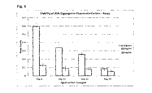
The data are shown in Fig. 5, with 1 SD error bars. On day zero the assay
performs as
expected, giving a high signal in the absence of digoxin, and a low signal in
the presence of
digoxin. However, it can be seen that the assay performance is changing over
time, with the
signal in the absence of digoxin reducing upon storage of the carbon
conjugate. The signal in
chamber 1 of these assays (the minimum binding control) remains largely
unchanged over
time, it is the signal in chambers 2 (anti-digoxin) and 3 (anti-FITC) which is
changing, with the
signal dropping over time in both chambers. Fig. 6 shows the binding rate in
chamber 3 over
time. The signal in chamber 3 is independent of the digoxin concentration,
since the binding is
to the fluorescein group on the carbon particle. The drop in signal would
suggest that the
BSA-digoxigenin-F1TC conjugate is desorbing from the surface of the carbon
particle over
time upon storage. Any unbound BSA-digoxigenin-FITC in solution would compete
for the
binding sites on the surface and lower the rate of binding. This was confirmed
by
centrifugation, pelleting, washing and resuspension of the carbon conjugate.
This led to an
increase in binding in chamber 3, as shown in Fig. 7.
Example 13
Assay performance and stability of digoxigeninfiluorescein dextran carbon
A competitive assay for digoxin was carried out using the carbon conjugate
prepared in
Example 11. The reaction conditions were identical to those used in Example
12, except for
the carbon conjugate. The ratiometric assay counts are shown in Fig. 8. It is
observed that the
final assay signal (ratiometric output) shows no change over the 29 days that
the carbon was
stored at 4 C. The chamber 3 values are shown in Fig. 9, confirming that there
was no
deterioration in the conjugate over this period.
=
19