Note: Descriptions are shown in the official language in which they were submitted.
CA 02867367 2014-10-15
BALUSTER CONNECTOR
BACKGROUND
The embodiments of the invention relate generally to the field of railings.
Railings may contain several members that can be transported as disparate
pieces,
such as in knock down form, and assembled at the final location of the
railing. The
railing may be assembled with various horizontal members including rails, hand
rails,
grab rails, guard rails, bottom rails, mid rails and inclined rails, as well
as vertical
elements such as balusters, pickets, posts and spindles. The vertical members
of the
railing may be directly connected to the horizontal members by a variety of
fastening
means, such as welding, adhesives, screws, nails or connectors. Railings may
be
assembled on essentially flat, horizontal surfaces, or on sloped surfaces,
such as along a
stairway.
BRIEF SUMMARY
The embodiments of the invention relate to a connector for a railing system
having a plurality of balusters disposed between an upper rail and a lower
rail for
connecting a baluster to one of the upper and lower rails. The connector
comprises a base
having a periphery and a central opening therein extending between first and
second
surfaces that are positioned at an inclined angle with respect to one another
and a
retaining member having a mounting portion configured to mount an end of a
baluster at
one end and an interengaging member at an opposite end configured to be
rotatably
mounted to the base in juxtaposition with respect to the second surface of the
base. In a
horizontal position, the interengaging member and the base form an axial
relationship
corresponding to an angle for the upper and lower railings in a horizontal
orientation, and
in a second inclined position, the interengaging member and the base form an
inclined
relationship corresponding to an angle for the upper and lower railings on an
inclined
staircase. When the base is mounted to one of the upper or lower rails of the
railing
system and moved to one of the horizontal or inclined positions with respect
to the
retaining member, the mounting portion of the retaining member can be mounted
to a
baluster to mount the baluster with respect to the upper or lower rail.
-1-
CA 02867367 2014-10-15
BRIEF DESCRIPTION OF THE DRAWINGS
In the drawings:
Figure 1 is a schematic representation of a portion of a railing assembly
according
to an embodiment of the invention.
Figure lA is an exploded view of the railing assembly of Figure 1 according to
an
embodiment of the invention.
Figure 2 is a schematic representation of a portion of a railing assembly
according
to an embodiment of the invention.
Figure 3 is an isometric view of a connector for use with a railing assembly
according to an embodiment of the invention.
Figure 4 is an isometric view of a connector for use with a railing assembly
according to an embodiment of the invention.
Figure 5 is an exploded view of the connector of Figures 3 and 4 according to
an
embodiment of the invention.
Figure 6 is a side view of the connector of Figure 3 according to an
embodiment
of the invention.
Figure 7 is a side view of the connector of Figure 4 according to an
embodiment
of the invention.
Figure 8 is sectional view of a connector mounting a baluster to a rail
according to
an embodiment of the invention.
Figure 9 is sectional view of a connector mounting a baluster to a rail
according to
an embodiment of the invention.
Figure 10 is an isometric view of a connector for use with a railing assembly
according to an embodiment of the invention.
Figure 11 is an isometric view of a connector for use with a railing assembly
according to an embodiment of the invention.
Figure 12 is an exploded view of the connector of Figures 10 and 11 according
to
an embodiment of the invention.
Figure 13 is a side view of the connector of Figure 10 according to an
embodiment of the invention.
-2-
CA 02867367 2014-10-15
Figure 14 is a side view of the connector of Figure 11 according to an
embodiment of the invention.
Figure 15 is an isometric view of a connector for use with a railing assembly
according to an embodiment of the invention.
DETAILED DESCRIPTION
Figures 1 and 2 illustrate a railing assembly 10 installed on a flat,
horizontal
surface (Figure 1) and a sloped surface (Figure 2). As used herein, a railing
assembly
installed on a flat, horizontal surface, such as a deck floor, for example, is
referred to as a
horizontal railing assembly and a railing assembly installed on a sloped
surface, such as a
hill side or along a stairway, is referred to as an angled railing assembly.
Referring now to Figures 1, 1A, and 2, the railing assembly 10 includes an
upper
rail 12 and a lower rail 14 with a plurality of balusters 16 extending
therebetween. Each
baluster 16 can be connected with the upper and lower rails 12, 14 by a
connector 18,
which is described in more detail below. When the upper and lower rails 12, 14
are
installed on a horizontal surface (Figure 1), the upper and lower rails 12, 14
are referred
to as horizontal rails; when the rails 12, 14 are assembled on a sloped
surface (Figure 2),
the rails 12, 14 are referred to as angled rails.
The rails 12 and 14 can be constructed of any known material, including, but
not
limited to, metal and metal alloys, such as wrought iron, iron, copper, brass,
aluminum,
stainless steel, and galvanized steel, as well as, wood, wood composite or
plastic.
Similarly, the balusters 16 can be hollow and constructed of similar materials
as the rails
12 and 14, although it is within the scope of the invention for the balusters
16 and rails 12
and 14 to be made from different materials. Each of these rails 12 and 14 and
balusters
16 can be constructed using known forming processes, including but not limited
to,
extrusion, forging, molding, and cutting. The connector 18 can be made from
any
suitable metal, metal alloy, wood, wood composite or plastic, but is
preferably made from
plastic.
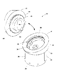
Referring now to Figures 3-5, the connector 18 is a two piece-connector that
includes a base 20 and a baluster retaining member 22. The base 20 is
configured to be
fastened to the upper or lower rail 12, 14 and the retaining member 22 is
configured to
mount a baluster 16. The retaining member 22 includes a mounting portion 24
which is
-3-
CA 02867367 2014-10-15
configured to be received within the baluster 16, which is formed as a hollow
cylinder
(see Figure 1A). The mounting portion 24 can be sized and shaped so as to
frictionally
retain the baluster 16 inserted thereon, and can optionally include rib
protrusions 26 to
facilitate retaining the baluster 16. The mounting portion 24 can extend from
a baluster
mounting face 30 of the retaining member 22. Alternatively, the baluster 16
can be slid
onto the mounting portion 24 and held in place using any other suitable
mechanical or
non-mechanical fastener, such as a snap-fit, a resilient detent, a connector
pin, or an
adhesive, for example. In another example, the baluster 16 can simply fit
loosely around
the mounting portion 24. Alternatively, the baluster 16 and the mounting
portion 24 can
be sized and shape so that the mounting portion 24 receives the baluster 16
within a
channel provided in the mounting portion 24. In this example, the baluster 16
would not
need to be hollow and could be solid.
The mounting portion 24 can be hollow to provide a central fastener aperture
32
for receipt of a fastener, such as a screw (see Figures 8 and 9), for
attaching the connector
18 to the adjacent rail 12, 14. The fastener aperture 32 may be provided with
a tapered
screw seat at an outer end thereof (see Figures 8 and 9). The retaining member
22 further
includes a female interengaging member 34 and a mating surface 36 opposite the
baluster
mounting face 30. As illustrated the fastener aperture 32 of the retaining
member 22 may
be smaller than the fastener aperture 40 of the base 20
Still referring to Figures 3-5, the base 20 includes a central opening forming
a
fastener aperture 40 through which a fastener inserted into the retaining
member 22
extends for mounting the connector 18 to the adjacent rail 12, 14. The base 20
includes a
rail mounting surface 42 and a mating surface 44. The base 20 also includes a
male
interengaging member 46 configured to be received by the female interengaging
member
34 of the retaining member 22. When assembled, the male interengaging member
46 of
the base 20 is received by the female interengaging member 34 of the retaining
member
22 such that the respective mating surfaces 36 and 44 of the retaining member
22 and
base 20, respectively, are adjacent one another (see Figures 8 and 9). While
the
embodiments of the invention are described in the context of the base 20
including the
male interengaging member 46 and the retaining member 22 including the female
interengaging member 34, it is understood that the location of the male and
female
-4-
CA 02867367 2014-10-15
connecting portions 46, 34 can be switched between the base 20 and retaining
member 22
without deviating from the scope of the invention.
The female interengaging member 34 of the retaining member 22 is configured to
receive the male interengaging member 46 of the base 20 such that the base 20
can rotate
relative to the retaining member 22. The female interengaging member 34 can
receive
the male interengaging member 46 through a threaded connection. For example,
as
illustrated in Figure 5, the female interengaging member 34 can include one or
more
grooves 50 which receive corresponding threads 52 on the male interengaging
member
46. The female interengaging member 34 can include a pair of stops 60, which,
in
combination with a corresponding stop 62 on the male interengaging member 46
can
limit the rotation of the base 20 relative to the retaining member 22.
As can best be seen in Figures 3 and 4, the rail mounting surface 42 of the
base 20
can also be provided with a pair of opposing grooves 64 which can be
configured to
receive the head of a screw driver to facilitate rotation of the base 20
relative to the
retaining member 22. Alternatively, the base 20 can be rotated by hand by
grasping one
of the base 20 or retaining member 22 and twisting one of the base 20 or
retaining
member 22 relative to the other. The rail mounting surface 42 can also
optionally be
provided with indicia 66, such as arrows and/or text, as illustrated, or other
graphics to
provide use instructions to the user.
The mating surface 36 of the retaining member 22 can be provided at an angle
relative to the baluster mounting face 30. Similarly, the mating surface 44 of
the base 20
can be provided at an angle relative to the rail mounting surface 42. As can
best be seen
in Figures 3, 4, 6 and 7, the base 20 can be rotated relative to the retaining
member 22 to
a first position, illustrated in Figures 3 and 6, in which the rail mounting
surface 42 is
orthogonal to the central axis 66 of the mounting portion 24 of the retaining
member 22.
The base 20 can also be rotated relative to the retaining member 22 to a
second position,
illustrated in Figures 4 and 7, in which the rail mounting surface 42 is at a
predetermined
angle with respect to the central axis 66 of the mounting portion 24. The
stops 60, 62 on
the retaining member 22 and base 20, respectively, can be configured such that
a 180
degree rotation of the base 20 relative to the retaining member 22 moves the
base 20
between the first and second positions. In this manner, the relative rotation
of the base 20
-5-
CA 02867367 2014-10-15
and the retaining member 22 allows the connector 18 to be used to mount the
balusters 16
to both a horizontal rail 12, 14 (illustrated in Figure 1) and an angled rail
12, 14
(illustrated in Figure 2).
Referring now to Figure 8, to mount the baluster 16 to a horizontal lower rail
14,
the base 20 can be rotated to the first position such that the rail mounting
surface 42 of
the base 20 is orthogonal to the central axis of the mounting portion 24. In
this position,
the rail mounting surface 42 presents a face parallel to a surface of the
horizontal rail 14
to which the baluster 16 is to be mounted. In use, the base 20 can be rotated
to the first
position and a screw 70 inserted through the fastener aperture 32 of the
retaining member
22 and the fastener aperture 40 of the base 20 and into the lower rail 14. The
baluster 16
can then be slid over the mounting portion 24 and frictionally retained
thereon. The
connector 18 can be used in a similar manner to mount the balusters 16 to a
horizontal
upper rail 12. When the baluster 16 is mounted on the connector 18, the
retaining
member 22 prevents an end of the baluster 16 from directly contacting the rail
14.
Referring now to Figure 9, to mount the baluster 16 to an angled lower rail
14,
such as may be used along a stairway, the base 20 can be rotated to the second
position
such that the rail mounting surface 42 of the base 40 is at a predetermined
angle relative
to the central axis of the mounting portion 24. In this position, the rail
mounting surface
42 can present a face parallel to an angled surface of the rail 14 to which
the baluster 16
is to be mounted. As described with respect to Figure 8, the base 20 can be
rotated to the
second position and a screw 70 inserted through the fastener aperture 32 of
the retaining
member 22 and the fastener aperture 40 of the base 20 and into the lower rail
14. The
baluster 16 can then be slid over the mounting portion 24 and frictionally
retained
thereon. The connector 18 can be used in a similar manner to mount the
baluster 16 to an
angled upper rail 12.
The angle of the mating surfaces 36 and 44 of the retaining member 22 and base
20, respectively, can be configured to provide a desired angle of the baluster
16 based on
the angle of the rail 12, 14 to which the baluster 16 is to be mounted. For
example,
stairways are typically constructed at a predetermined angle relative to the
horizontal
surface from which they extend (i.e. the floor). However, typically, it is
still desired that
the balusters be constructed orthogonal to the horizontal surface. The mating
surfaces 36,
-6-
CA 02867367 2014-10-15
44 can be provided at a predetermined angle, such as half of the angle of the
stairway
with which the balusters 16 are to be installed. In the example of a typical
stairway
constructed at a 35 degree angle relative to horizontal, the mating surfaces
36, 44 can be
provided at 17.5 degrees relative to the baluster and rail mounting surfaces
30, 42. In this
manner, when the base 20 is rotated to the second position and the connector
18 is used to
mount the balusters 16 to a rail 12, 14 constructed at a 35 degree angle, the
balusters 16
will extend straight between the rails 12, 14, i.e. orthogonal to the
horizontal surface the
stairway is constructed on.
Figures 10-14 illustrate another embodiment of the invention comprising a
connector 118 that is similar to the connector 18 except for the shape of the
connector
118. Therefore, elements in the connector 118 similar to those of connector 18
will be
numbered with the prefix 100.
As can best be seen in Figures 10-12, the connector 118 has a generally
polygonal
shape compared to the circular shape of the connector 18. The connector 18 is
configured to be used with balusters having a circular cross-section, whereas
the
connector 118 is configured for use with balusters having a polygonal cross-
section. As
illustrated in Figures 10-12, the mounting portion 124 can have a generally
square cross-
section for mounting a baluster having a corresponding square cross-section
(not shown).
It is also within the scope of the invention for the mounting portion 124 to
have any
suitable polygonal cross-section to mount a baluster having a corresponding
polygonal
cross-section, non-limiting examples of which include a triangular,
rectangular,
hexagonal, diamond, or octagonal cross-section. In addition, while the
connector 18 is
illustrated for use with a baluster 16 having a circular cross-section, it is
within the scope
of the invention for the connector 18 to have a mounting portion 24 configured
for
mounting a baluster having an oval cross-section.
Still referring to Figures 10-12, the base 120 and retaining member 122 also
have
a polygonal cross-section. The size and shape of the base 120 and retaining
member 122
are generally configured to correspond to the dimensions of the baluster such
that when
assembled, exterior edges of the baluster are flush with the exterior edges of
the
connector 118, in a manner similar to that shown in Figures 8 and 9 for the
connector 18
and baluster 16. However, it will be understood that the relative dimensions
of the
-7-
CA 02867367 2014-10-15
connector 18, 118 and baluster 16 can be configured to highlight or expose
more or less
of the connector 18, 118 when assembled with the baluster 16. For example, the
base 20,
120 and/or retaining member 22, 122 can be provided with a decorative shape or
accent
to provide a desired aesthetic to the assembly.
Referring now to Figures 13 and 14, the base 120 and retaining member 122 can
be rotated relative to each other for use in mounting balusters to both a
horizontal and
angled rail in the same manner as described above for the connector 18 with
respect to
Figures 6-9.
Figure 15 illustrates another embodiment of the invention comprising a
connector
218 that is similar to the connector 18 except for the shape of the fastener
aperture.
Therefore, elements in the connector 218 similar to those of connector 18 will
be
numbered with the prefix 200. The connector 218 includes a fastener aperture
240 which
is similar to the fastener aperture 40 of the connector 18 of Figures 3-4,
except for that
the fastener aperture 240 is circular instead of oval. The oval fastener
apertures 40 and
140 of the connectors 18 and 118, respectively, provide space for inclusion of
the
optional screw driver grooves 64 and 164 which can be used to facilitate
rotation of the
base 20, 120 relative to the retaining member 22, 122. In addition, the oval
aperture 40,
140 can provide more room for the fastener to be inserted during assembly and
then
further prevent relative rotation of the base 20 with the fastener inserted
therein.
While the connector 18 is illustrated as being visible on a surface of the
rail 12, 14
in Figures 1-2 and 8-9, it is within the scope of the invention for any of the
connectors 18,
118, 218 described herein to be countersunk within an aperture provide in the
rail 12, 14
such that the baluster mounting face 30, 130, 230 is flush or positioned below
the surface
of the rail so that no portion of the connector 18, 118, 218 is visible when
assembled with
a baluster 16 and so that an end of the baluster 16 is generally flush with
the surface of
the rail 12, 14 or received within the aperture in the rail 12, 14.
In addition, while the connectors 18, 118, 218 are described in the context of
mounting balusters 16 to both upper and lower rails 12, 14, it will be
understood that only
a single connector 18, 118, 218 can be used to mount the baluster 16 to only
one of the
upper or lower rails 12, 14. It is also within the scope of the invention for
the connectors
-8-
CA 02867367 2014-10-15
18, 118, 218 to be used to mount the baluster 16 at one or both ends to a
surface other
than rail, such as a floor.
The embodiments of the invention described herein provide a baluster connector
for use in assembling balusters and railings that can be used for both
horizontal and
angled railing assemblies. Typically, separate connectors are provided for
horizontal and
angled railing assemblies or, if a single connector is used, the installer is
required to cut
the end of the baluster at an angle in order to assemble straight, vertical
balusters between
the angled rails. Providing separate connectors for horizontal and angled
assemblies can
be confusing to the consumer, increase production and shipping costs and
increase
retailer cost, as the separate connectors require more shelf space for display
and one type
of connector may sell faster than the other. Requiring the baluster to be cut
on angle for
installation on sloped surfaces, such as stairways, is time consuming for the
installer, and,
if mistakes are made during cutting, can increase costs.
The inventive connectors 18, 118, 218 described herein provide a single
connector which can be simply rotated for use in either horizontal railing
assemblies or
angled railing assemblies. A single connector for use in both installation
conditions saves
production, shipping and storage costs and also provides convenience to
consumers and
retailers. In addition, the connector can be used to mount balusters to angled
rails
without the need to cut the baluster end on an angle, further increasing the
ease of use for
the consumer and installer. In addition, inventive connectors 18, 118, 218
described
herein support the ends of the balusters on the baluster mounting face 30,
130, 230, which
can prevent the ends of the balusters from coming into direct contact with the
rails. This
can be important depending on the materials used to make the balusters and the
rails. For
example, it is typically not recommended that aluminum balusters directly
contact certain
types of treated wood, as some of the materials used to treat the wood may
interact with
the metal baluster in an undesirable manner.
To the extent not already described, the different features and structures of
the
various embodiments of the invention may be used in combination with each
other as
desired. For example, one or more of the features illustrated and/or described
with
respect to one of the connectors 18, 118, 218 can be used with or combined
with one or
more features illustrated and/or described with respect to the other of the
18, 118, 218.
-9-
CA 02867367 2014-10-15
That one feature may not be illustrated in all of the embodiments is not meant
to be
construed that it cannot be, but is done for brevity of description. Thus, the
various
features of the different embodiments may be mixed and matched as desired to
form new
embodiments, whether or not the new embodiments are expressly described.
While the invention has been specifically described in connection with certain
specific embodiments thereof, it is to be understood that this is by way of
illustration and
not of limitation. The scope of the claims should not be limited by particular
embodiments set forth herein, but should be construed in a manner consistent
with the
specification as a whole.
-10-