Note: Descriptions are shown in the official language in which they were submitted.
CA 02868641 2014-09-26
REMOVABLE BATTERY FIXING ASSEMBLY OF ELECTRIC VEHICLE
AND FIXING METHOD THEREOF
FIELD OF THE INVENTION
[0001] The present invention relates to a removable battery fixing
assembly,
and more particularly to a removable battery fixing assembly of an electric
vehicle
and a fixing method thereof.
BACKGROUND OF THE INVENTION
[00021 Nowadays, with increasing awareness of environmental protection,
more and more products are designed in views of power-saving concepts. As the
demands on clean and renewable energy are increased, electric vehicles are
developed. Generally, an electric vehicle is powered by the built-in battery.
For
providing enough electric energy to drive the electric vehicle to move, a
battery
module with plural built-in batteries must be employed. Consequently, the
battery module may occupy some space of the electric vehicle. Moreover, for
facilitating charging, maintaining or replacing the batteries of the electric
vehicle,
the battery module is designed to be removable. The removable battery module
is
widely used in the power supply system of the electric vehicle.
[0003] As the volume of the electric vehicle is increased, the battery
module
with high power for the electric vehicle has large volume and weight. For
example, the battery module of an electric rail vehicle, an electric bus or an
electric
truck is larger and heavier than the battery module of an electric motor coach
or an
electric scooter. In case that the larger and heavier battery module is
installed in
the vehicle body, the installation space and the cooling efficacy of the
installation
CA 02868641 2014-09-26
space should be taken into consideration. Moreover, it is necessary to
securely fix
the battery module in the limited space of the vehicle body and easily lock or
unlock the battery module. If the battery module is not securely fixed, the
battery
module with heavy weight is possibly loosened by the gravity or the
centrifugal
force during the driving period of the electric vehicle. Once the battery
module is
loosened, the function of the battery module is deteriorated. Furthermore, if
the
battery module is not securely fixed, the battery module is readily suffered
from
collision because of the trembling condition. Under this circumstance, the
battery
module may be damaged or crushed.
[0004] Therefore, there is a need of providing an improved removable
battery
fixing assembly of an electric vehicle and an improved fixing method thereof
in
order to securely fix the battery module in the limited space of the vehicle
body,
prevent the battery module from being loosened or collided, maintain the
battery
module within the vehicle body, and facilitate replacing the batteries of the
electric
vehicle.
SUMMARY OF THE INVENTION
[0005] The present invention provides a removable battery fixing assembly
of an electric vehicle in order to securely fix the removable battery module
within
the electric vehicle and reduce the installation space of the electric
vehicle.
[0006] The present invention provides a fixing method for fixing a
removable
battery module of an electric vehicle, in which the removable battery module
is
easily installed into the electric vehicle by user and the removable battery
module
is easily locked or unlocked for facilitating replacing the batteries of the
electric
vehicle.
[0007] In accordance with an aspect of the present invention, there is
provided a removable battery fixing assembly of an electric vehicle comprising
a
2
CA 02868641 2014-09-26
removable battery module and a fixing device. The removable battery module
comprises a main body having a first side surface and a second side surface.
The
first side surface and the second side surface are located adjacent to each
other.
At least one guiding bar is disposed on the first side surface. The fixing
device is
installed in a vehicle body of an electric vehicle. The fixing device includes
a
base, a driving part, a main transmission part, a guiding part, a first
stopping part,
and a second stopping part. The driving part is disposed on the base. The main
transmission part is connected with the driving part. The guiding part is
disposed
on the base. The first stopping part is pivotally coupled with the main
transmission part. The second stopping part is pivotally coupled with the main
transmission part through plural connection elements.
For installing the
removable battery module in the vehicle body of the electric vehicle, the at
least
one guiding bar on the first side surface of the removable battery module is
aligned
with the guiding part and moved along the guiding part. When the removable
battery module is moved to a specified position, the main transmission part is
driven by the driving part to be moved horizontally, so that the first
stopping part is
correspondingly rotated to urge against an end part of the guiding bar. When
the
removable battery module is moved to the specified position, the second
stopping
part is correspondingly driven by the plural connection elements to lock the
second
side surface of the removable battery module.
[0008]
In accordance with another aspect of the present invention, there is
provided a fixing method for a removable battery fixing assembly of an
electric
vehicle. The fixing method includes the following steps. Firstly, a removable
battery module is provided. The removable battery module has a first side
surface and a second side surface. The first side surface and the second side
surface are located adjacent to each other. At least one guiding bar is
disposed on
3
CA 02868641 2014-09-26
the first side surface. Then, the guiding bar of the removable battery module
is
aligned with a guiding part of the fixing device of an electric vehicle, and
the
removable battery module is moved along the guiding part of the fixing device
to a
specified position. Then, a driving part of the fixing device is enabled to
drive a
main transmission part to be moved horizontally, so that a first stopping part
pivotally coupled with the main transmission part is correspondingly rotated
to
urge against an end part of the guiding bar. While the main transmission part
is
moved horizontally, a second stopping part is correspondingly rotated to lock
the
second side surface of the removable battery module, wherein the second
stopping
part is pivotally coupled with the main transmission part through plural
connection
elements.
[0009] The above contents of the present invention will become more
readily
apparent to those ordinarily skilled in the art after reviewing the following
detailed
description and accompanying drawings, in which:
BRIEF DESCRIPTION OF THE DRAWINGS
[0010] FIG 1 schematically illustrates an electric vehicle with a
removable
battery module according to an embodiment of the present invention;
[0011] FIG. 2 is a schematic perspective view illustrating the removable
battery module of the electric vehicle according to the embodiment of the
present
invention;
[0012] FIG. 3 is a schematic perspective view illustrating the
relationship
between the removable battery module and a fixing device according to an
embodiment of the present invention, in which the fixing device is in an
unlocking
status;
[0013] FIG 4 is a schematic perspective view illustrating the
relationship
between the removable battery module and the fixing device according to the
4
CA 02868641 2014-09-26
embodiment of the present invention, in which the fixing device is in a
locking
status;
[0014] FIG 5 is a schematic exploded view illustrating the fixing device
according to the embodiment of the present invention and taken along a first
viewpoint;
[0015] FIG. 6 is a schematic exploded view illustrating the fixing device
according to the embodiment of the present invention and taken along a second
viewpoint; and
[0016] FIG 7 is a flowchart illustrating a fixing method of fixing a
removable
battery module on a fixing device according to an embodiment of the present
invention.
DETAILED DESCRIPTION OF THE PREFERRED EMBODIMENT
[0017] The present invention will now be described more specifically with
reference to the following embodiments. It is to be noted that the following
descriptions of preferred embodiments of this invention are presented herein
for
purpose of illustration and description only. It is not intended to be
exhaustive or
to be limited to the precise form disclosed.
[0018] Please refer to FIG1, which schematically illustrates an electric
vehicle with a removable battery module according to an embodiment of the
present invention. As shown in FIG. 1, the inventive removable battery fixing
assembly of the electric vehicle 3 (as shown in FIG. 3) is applied to an
electric
vehicle 1. The electric vehicle 1 is a large-sized electric vehicle. An
example of
the electric vehicle 1 includes but is not limited to an electric bus, an
electric rail
vehicle, or an electric truck. As shown in FIG. 1, the removable battery
module 2
is installed in an accommodation space 100 of a vehicle body 10 of the
electric
vehicle 1. In this embodiment, the electric vehicle 1 comprises one or more
CA 02868641 2014-09-26
removable battery modules 2, which are located at a lateral side of the
vehicle body
of the electric vehicle 1 or located at two lateral sides of the vehicle body
10.
Preferably, the electric vehicle 1 comprises two battery modules 2. It is
noted that
the number of the battery modules 2 may be varied according to practical
requirements.
[0019] Please refer to FIG 2, which is a schematic perspective view
illustrating the removable battery module of the electric vehicle according to
the
embodiment of the present invention. As shown in FIG 2, the removable battery
module 2 comprises a main body 20. The main body 20 has a first side surface
21 and a second side surface 22. The first side surface 21 and the second side
surface 22 are located adjacent to each other, and at least one guiding bar
211 is
disposed on the first side surface 21. In this embodiment, two parallel
guiding
bars 211 are disposed on the first side surface 21. It is noted that the
number of
the guiding bars 211 is not restricted. In some embodiments, the main body 20
further comprises a third side surface 23. The third side surface 23 is
opposed to
the first side surface 21, and at least one guiding bar 231 is disposed on the
third
side surface 23. The number of the guiding bars 231 is not restricted. The
structure and position of the guiding bar 231 are similar to that of the
guiding bar
211 disposed on the first side surface 211, and it isn't described redundantly
hereinafter.
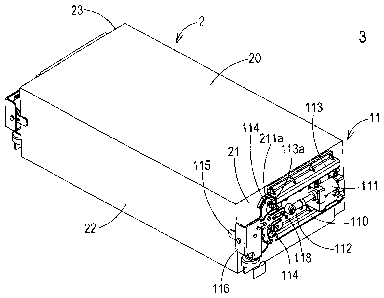
[0020] Please refer to FIGS. 1, 3 and 4. FIG. 3 is a schematic
perspective
view illustrating the relationship between the removable battery module and a
fixing device according to an embodiment of the present invention, in which
the
fixing device is in an unlocking status. FIG. 4 is a schematic perspective
view
illustrating the relationship between the removable battery module and the
fixing
device according to the embodiment of the present invention, in which the
fixing
6
CA 02868641 2014-09-26
device is in a locking status. As shown in FIGS. 1, 3 and 4, the removable
battery
fixing assembly of the electric vehicle 3 includes the removable battery
module 2
and the fixing device 11. The fixing device 11 is installed in the vehicle
body 10
of the electric vehicle 1, and the fixing device 11 is used for fixing the
removable
battery module 2. In this embodiment, the fixing device 11 comprises a base
110,
a driving part 111, a main transmission part 112, at least one guiding part
113, at
least one first stopping part 114, and a second stopping part 115. The driving
part
111 is disposed on the base 110. The main transmission part 112 is connected
with the driving part 111 and performs a horizontal reciprocating movement by
the
driving of the driving part 111. The guiding part 113 is disposed on the base
110.
The guiding part 113 has a guiding groove 113a corresponding to the guiding
bar
211 of the removable battery module 2. The first stopping part 114 is
pivotally
coupled with the main transmission part 112. The second stopping part 115 is
pivotally coupled with the main transmission part 112 through plural
connection
elements. For installing the removable battery module 2 in the accommodation
space 100 of the vehicle body 10 of the electric vehicle 1, the guiding bars
211
disposed on the first side surface 21 of the removable battery module 2 are
firstly
aligned with the guiding parts 113 of the fixing device 11. Then, the
removable
battery module 2 is pushed to move along the guiding groove 113a of the
guiding
part 113. When the removable battery module 2 is moved to a specified position
(see FIG 4), the main transmission part 112 is driven by the driving part 111
to be
moved horizontally. As the main transmission part 112 is moved horizontally,
the
first stopping part 114 connected with the main transmission part 112 is
forced to
rotated and upraised correspondingly so as to urge against an end part 211a of
the
upper guiding bar 211 (see FIG. 4). At the same time, the second stopping part
7
CA 02868641 2014-09-26
115 is correspondingly driven by the plural connection elements to lock the
second
side surface 22 of the removable battery module 2.
[0021]
Please refer to FIGS. 5 and 6. FIG 5 is a schematic exploded view
illustrating the fixing device according to the embodiment of the present
invention
and taken along a first viewpoint. FIG 6 is a schematic exploded view
illustrating
the fixing device according to the embodiment of the present invention and
taken
along a second viewpoint. Hereinafter, the detailed configurations and the
operations of the fixing device will be illustrated with reference to FIGS. 5
and 6.
The base 110 of the fixing device 11 is used to support the other components
of the
fixing device 11. The base 110 is made of a metallic material, but is not
limited
thereto. In this embodiment, the base 110 further comprises a bracket 110a for
supporting the driving part 111. An example of the driving part 111 includes
but
is not limited to a hydraulic driving element, an oil pressure driving
element, a
pneumatic driving element or a screw rod. In this embodiment, the driving part
111 is a pneumatic cylinder. Alternatively, in some other embodiments, the
driving part 111 is a stepper motor or any other appropriate driving element
that
drives reciprocating movement of the main transmission part 112. The guiding
part 113 is disposed on the base 110. The guiding part 113 has the guiding
groove
113a corresponding to the guiding bar 211 of the removable battery module 2.
The guiding bar 211 is movable along the guiding groove 113a of the guiding
part
113. In this embodiment, the removable battery module 2 has two guiding bars
211, and the fixing device 11 has two guiding parts 113 corresponding to the
two
guiding bars 211 of the removable battery module 2. These two guiding parts
113
are located at an upper side and a lower side of the base 110 and
corresponding to
the two guiding bars 211, respectively. It is noted that the locations and
mating
8
CA 02868641 2014-09-26
structures of the two guiding parts 113 and the two guiding bars 211 may be
varied
according to practical requirements.
[0022] Please refer to FIGS. 5 and 6 again. The main transmission part
112
is connected with the driving part 111. In this embodiment, the main
transmission
part 112 is a flat plate with a horizontal arm and a vertical arm, but it is
not limited
thereto. Moreover, in this embodiment, the main transmission part 112 further
comprises at least one guiding slot 112a. After a specified fixing pin 118 is
penetrated through the base 110 and the guiding slot 112a of the main
transmission
part 112, the main transmission part 112 is coupled with the base 110. Under
this
circumstance, the reciprocating moving distance of the main transmission part
112
is limited by the two ends 112b, 112c of the guiding slot 112a. Moreover,
according to the position of the fixing pin 118 relative to the guiding slot
112a, a
locking status and an unlocking status of the fixing device 11 may be defined.
For example, when the guiding slot 112a of the main transmission part 112 is
moved and the fixing pin 118 is located at the first end 112b of the guiding
slot
112a, the fixing device 11 is in the unlocking status (see FIG 3). Whereas,
when
the fixing pin 118 is located at the second end 112c of the guiding slot 112a,
the
fixing device 11 is in the locking status (see FIG 4). In this embodiment, the
fixing device 11 has plural fixing pins 118 to fix or couple associated
components.
Moreover, the fixing device 11 further comprises plural fastening elements 119
(e.g.
screws or nuts) for assisting in fastening associated components. It is noted
that
numerous modifications and alterations of the fastening elements and the
coupling
elements may be made while retaining the teachings of the invention.
[0023] When the driving part 111 is operated, the main transmission part
112
connected with the driving part 111 is moved horizontally by the driving of
the
driving part 111. When the main transmission part 112 is moved and the fixing
9
CA 02868641 2014-09-26
pin 118 is located at the first end 112b of the guiding slot 112a (i.e. the
fixing
device 11 is in the unlocking status), the first stopping part 114 connected
with the
main transmission part 112 is inclined with respect to the main transmission
part
112. Namely, the first stopping part 114 is inclined when the fixing device 11
is
in the unlocking status. When the main transmission part 112 is moved
horizontally by the driving of the driving part 111 and the fixing device 11
is in the
locking status, the first stopping part 114 is rotated and ascended
correspondingly
and further urges against the end part 211a of the guiding bar 211 on the
first side
surface 21 of the removable battery module 2 (see FIG 4). Under this
circumstance, the first side surface 21 of the removable battery module 2 is
locked
by the first stopping part 114. In this embodiment, since the first stopping
part
114 is pivotally coupled with the main transmission part 112 through plural
linking
elements 114b-114c, linking arm 114a and plural fixing pins 118, the first
stopping
part 114 is correspondingly rotated and ascended to urge against and stop the
end
part 211a of the guiding part 211. Moreover, the removable battery module 2
has
two guiding bars 211 disposed on the first side surface 21, and the fixing
device 11
comprises two first stopping parts 114 corresponding to the guiding bars 211,
but it
is not limited thereto. When the fixing device 11 is in the locking status,
the
upper first stopping part 114 is ascended to urge against and stop the upper
guiding
bar 211 of the removable battery module 2 and the lower first stopping part
114 is
descended to urge against and stop the lower guiding bar 211 of the removable
battery module 2. Consequently, the guiding bars 211 disposed on the first
side
surface 21 of the removable battery module 2 can be securely locked when the
fixing device 11 is in the locking status.
[0024]
Please refer to FIGS. 3, 4, 5 and 6 again. The fixing device 11
further comprises a fixing seat 116 and a guiding wheel 117. In this
embodiment,
CA 02868641 2014-09-26
the guiding wheel 117 is disposed under the fixing seat 116. The fixing seat
116
is similar to the base 110. The fixing seat 116 is substantially a plate
structure
and made of a metallic material. Comparing the fixing seat 116 with the base
110,
the bottom of the fixing seat 116 further comprises bent piece.
An
accommodation space 116a is defined by the inner walls of the fixing seat 116
for
accommodating the plural connection elements. Consequently, the installation
space of the fixing device 11 is saved. As the main transmission part 112 is
moved horizontally toward the fixing seat 116 or away from the fixing seat
116,
the plural connection elements are correspondingly moved upwardly or
downwardly. For example, the plural connection elements comprises connection
arms 115a, 115c and connection piece 115b. An end of the connection arm 115a
is pivotally coupled with the vertical arm of the main transmission part 112,
and
the other end of the connection arm 115a is pivotally coupled with an end of
the
connection piece 115b. As the main transmission part 112 is moved horizontally
back and forth, the connection arm 115a is rotated by an angle, and thus the
connection piece 115b is correspondingly ascended or descended. In addition,
an
end of the connection arm 115c is pivotally coupled with the other end of the
connection piece 115b, and the other end of the connection arm 115c is
pivotally
coupled with the second stopping part 115. As the connection piece 115b is
ascended or descended, the connection ami 115c is correspondingly rotated. As
the connection arm 115c is rotated, the second stopping part 115 is
correspondingly
rotated to be in an upright state or a horizontal state. In a case that the
fixing
device 11 is in the unlocking status (see FIG 3), the second stopping part 115
is in
the upright state, and the second stopping part 115 is completely received
within
the accommodation space 116a of the fixing seat 116. In case that the main
transmission part 112 is moved horizontally by the driving of the driving part
111
11
CA 02868641 2014-09-26
and the fixing device 11 is in the locking status (see FIG 4), the second
stopping
part 115 is in the horizontal state because the second stopping part 115 is
rotated
downwardly through the transmission of the plural connection elements (i.e.
connection arms 115a, 115c and connection piece 115b). Under this
circumstance,
the second stopping part 115 is protruded out of the accommodation space 116a
of
the fixing seat 116. Consequently, the second side surface 22 of the removable
battery module 2 is stopped and locked by the second stopping part 115, and a
second locking mechanism for the removable battery module 2 is achieved.
[0025]
FIG. 7 is a flowchart illustrating a fixing method of fixing a removable
battery module on a fixing device according to an embodiment of the present
invention. The locking and unlocking operations of the inventive removable
battery fixing assembly of the electric vehicle 3 can be realized by referring
to FIG
7. The fixing method comprises the following steps. Firstly, in a step S40, a
removable battery module 2 is provided. The removable battery module 2 has a
first side surface 21 and a second side surface 22. The first side surface 21
and
the second side surface 22 are located adjacent to each other, and at least
one
guiding bar 211 is disposed on the first side surface 21. Then, in the step
S41 (see
FIG. 3), the guiding bar 211 of the removable battery module 2 is aligned with
the
guiding part 113 of the fixing device 11, and the removable battery module 2
is
moved along the guiding part 113 of the fixing device 11 to a specified
position.
When the removable battery module 2 is moved along the guiding part 113 of the
fixing device 11 to the specified position, the guiding bar 211 is received in
the
guiding part 113. It is noted that the guiding bar 211 is not completely
received in
the guiding part 113. That is, the end part 211a of the guiding bar 211 is
slightly
protruded out of the guiding part 113. In the subsequent locking procedure of
the
fixing device 11, the removable battery module 2 may be further moved to the
12
CA 02868641 2014-09-26
position corresponding to the locking status of the fixing device 11. After
the
removable battery module 2 is moved to the specified position, the step S42 is
performed. In the step S42 (see FIG 4), the driving part 111 of the fixing
device
11 is enabled to drive the main transmission part 112 connected with the
driving
part 111 to be moved horizontally back and forth, so that the first stopping
part 114
is correspondingly rotated upwardly to urge against and stop the end part 211a
of
the guiding bar 211 of the removable battery module 2. Meanwhile, in response
to the force of rotating the first stopping part 114 upwardly to urge against
and stop
the end part 211a of the guiding bar 211, the removable battery module 2 is
further
pulled to the position corresponding to the locking status of the fixing
device 11.
As mentioned above, the second stopping part 115 of the fixing device 11 is
pivotally coupled with the main transmission part 112 through the plural
connection elements (i.e. connection arms 115a, 115c and connection piece
115c).
As the main transmission part 112 is moved horizontally back and forth, the
second
stopping part 115 is correspondingly rotated to stop and lock the second side
surface 22 of the removable battery module 2. Meanwhile, the locking and
fixing
operation for the inventive removable battery fixing assembly of the electric
vehicle 3 is performed. On the other hand, when the removable battery module 2
needs to be unlocked, an unlocking operation of the fixing device 11 can be
achieved by performing inverse actions with respect to the fixing device 11.
While the fixing device 11 is in the unlocking status, the removable battery
module
2 may be withdrawn from the vehicle body 10 of the electric vehicle 1 easily.
[0026]
From the above descriptions, the present invention provides a
removable battery fixing assembly of the electric vehicle comprising a
removable
battery module and a fixing device. The fixing device is installed in a
vehicle
body of the electric vehicle. The fixing device comprises a first stopping
part and
13
CA 02868641 2014-09-26
a second stopping part. The first stopping part is used for urging against and
stopping a first side surface of the removable battery module. The second
stopping part is used for stopping and locking a second side surface of the
removable battery module. Due to the two locking mechanisms, the removable
battery module can be securely fixed in the vehicle body of the electric
vehicle.
Moreover, when the removable battery module needs to be withdrawn, the
removable battery module can be unlocked by performing inverse actions with
respect to the fixing device. While the fixing device is in the unlocking
status, the
removable battery module may be withdrawn from the vehicle body of the
electric
vehicle and replaced with a new one easily. Since the first side surface and
the
second side surface of the removable battery module are stopped and locked by
two locking mechanisms, the removable battery module is securely fixed in the
vehicle body of the electric vehicle and the possibility of causing short-
contact and
damage of the removable battery module from the vibrating and trembling
condition when the electric vehicle is operated will be minimized. Moreover,
due
to the configuration of the fixing device, the installation space for
accommodating
and fixing the removable battery module is largely saved. Moreover, the
locking
and unlocking operations of the fixing device can be performed easily, so that
the
removable battery module can be installed into and withdrawn from the vehicle
body of the electric vehicle by the user easily. The inventive removable
battery
fixing assembly of the electric vehicle has above-mentioned advantages, which
is
absent in the prior arts. The inventive removable battery fixing assembly of
the
electric vehicle is valuable in industry.
[0027]
While the invention has been described in terms of what is presently
considered to be the most practical and preferred embodiments, it is to be
understood that the invention needs not be limited to the disclosed
embodiment.
14
CA 02868641 2016-03-31
Various modifications and similar arrangements are encompassed.