Note: Descriptions are shown in the official language in which they were submitted.
CA 02868898 2014-10-28
PUMP DEVICE AND HYDRAULIC ACTUATOR
=
BACKGROUND OF THE INVENTION
1. Field of the Invention
[0001]
The present invention relates to a pump device and a hydraulic
actuator.
2. Description of the Related Art
[0002]
A hydraulic actuator includes a hydraulic cylinder (cylinder
device) that is extended and compressed by the fluid pressure of
hydraulic fluid, a pump device that supplies hydraulic fluid, .a
hydraulic circuit connected to the cylinder device to control the
fluid pressure of hydraulic fluid, and a tank that stores hydraulic
fluid. Various valves are provided to the hydraulic circuit, and
many of the valves are provided with a control block.
A relief valve of the valves in the hydraulic circuit may
be integrated with a pump (for example, see Japanese Patent
Application Laid-open No. H11-082411) .
[0003]
[Patent Document 1] Japanese Patent Application Laid-open
No. H11-082411
SUMMARY OF THE INVENTION
[0004]
In a production process of a hydraulic actuator, the
1
CA 02868898 2014-10-28
performance of a pump device alone is measured, and then, when the
pump device is assembled to a control block built in with multiple
valves such that a hydraulic circuit is connected, the performance
of the entire hydraulic circuit including the pump device is
measured.
In this manner, a performance measurement for a pump device
alone and a performance measurement for a hydraulic circuit need
to be performed in separate steps in a hydraulic actuator, and there
is a problem of a large number of steps. When the performance
measured for the hydraulic circuit does not satisfy the desired
performance, there is an additional work in which an assembled body
is disassembled for replacement of a valve or the like and
reassembled.
The present invention has been made in view of a situation
described above, and an object is to provide a pump device and a
hydraulic actuator that can reduce the number of steps for a
performance measurement.
[0005]
A pump device of the present invention comprises: a switching
valve for switching a flow of hydraulic fluid to one of a first
chamber and a second chamber of a cylinder device, an inside of
which is segmented into the first chamber and the second chamber
by a piston; a first chamber-side relief valve that is capable of
relieving pressure of a first chamber-side flow path connected to
the first chamber; and a second chamber-side relief valve that is
capable of relieving pressure of a second chamber-side flow path
2
CA 02868898 2014-10-28
connected to the second chamber.
In the pump device of the invention, the first chamber-side
relief valve and the second chamber-side relief valve may include
a pressure adjustment mechanism that adjusts a working pressure.
In the pump device of the invention, the first chamber-side
relief valve may be provided in a flow path between the switching
valve and the first chamber.
The pump device of the invention may be such that the first
chamber-side relief valve and the second chamber-side relief valve
are provided in a flow path between the switching valve and a pump
for feeding the hydraulic fluid, and a third relief valve including
a pressure adjustment mechanism that adjusts a working pressure
is provided in a flow path between the first chamber and the
switching valve.
A hydraulic actuator of the present invention includes a
cylinder device, an inside of which is segmented into a first chamber
and a second chamber by a piston, and a pump device including: a
switching valve for switching a flow of hydraulic fluid to one of
the first chamber and the second chamber; a first chamber-side
relief valve that is capable of relieving pressure of a first
chamber-side flow path connected to the first chamber; and a second
chamber-side relief valve that is capable of relieving pressure
of a second chamber-side flow path connected to the second chamber.
[0006]
With the pump device of the present invention, the number
of steps for a performance measurement can be reduced.
=
3
CA 02868898 2014-10-28
With the hydraulic actuator of the present invention, the
number of steps for a performance measurement can be reduced.
BRIEF DESCRIPTION OF THE DRAWINGS
[0007]
FIG. 1 is a perspective view showing the external appearance
of a trim tilt device including a pump device according to one
embodiment of the present invention;
FIG. 2 is a sectional view of amain section of the trim tilt
device;
FIG. 3 is a perspective view showing a housing and a cylinder
of the trim tilt device;
FIG. 4 is a schematic view showing the arrangement of a hull
and a ship propelling machine for which the trim tilt device is
used, when seen from the side;
FIG. 5 is a view showing a hydraulic circuit of the trim tilt
device;
FIG. 6 is a view showing the external appearance of a pump
device;
FIG. 7 is an exploded perspective view of the pump device
broken down into components;
FIG. 8 is a sectional view at a plane including an up blow
valve and a down blow valve along line VIII-VIII in FIG. 6;
FIG. 9 is a sectional view at a plane including a first open
valve and a second open valve of a switching valve and a third relief
valve along line IX-IX in FIG. 6;
4
CA 02868898 2014-10-28
FIG. 10 is a view showing a hydraulic circuit of a trim tilt
device in Embodiment 2; and
FIG. 11 is a view showing a hydraulic circuit of a trim tilt
device in Embodiment 3.
DESCRIPTION OF THE PREFERRED EMBODIMENTS
[0008]
<<Embodiment 1>>
An embodiment of the present invention will be described below
with reference to the accompanying drawings.
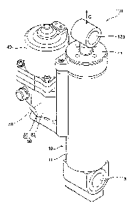
FIG. 1 is a perspective view showing the external appearance
of a trim tilt device 100 (as one example of a hydraulic actuator)
including a pump device 20 according to one embodiment of the present
invention. FIG. 2 is a sectional view of amain section of the trim
tilt device 100. FIG. 3 is a perspective view showing a housing
81 and a cylinder 11 of the trim tilt device 100.
[0009]
<Schematic configuration of trim tilt device 100>
As shown in FIGS. 1 and 2, the trim tilt device 100 includes
a cylinder device 10 extended and compressed by supply and discharge
of oil that is one example of hydraulic fluid, the pump device 20
that feeds oil, a motor 40 that drives the pump device 20, and a
tank 80 that stores oil.
[0010]
(Cylinder device 10)
As shown in FIG. 2, the cylinder device 10 includes the
CA 02868898 2014-10-28
cylinder 11 extending in an axis C direction, a piston 12 that is
arranged inside the cylinder 11 and slides along the axis C direction
of the cylinder 11, and a piston rod 13 that is fixed at one end
with the piston 12 to be displaced integrally with the piston 12
and that moves forward and backward in the axis C direction with
respect to the cylinder 11.
The inside of the cylinder device 10 is segmented by the piston
12 into a first chamber Yl and a second chamber Y2. The cylinder
device 10 extends when oil is supplied to the first chamber Yl,
and the cylinder device 10 compresses when oil is supplied to the
second chamber Y2. Oil is discharged from the second chamber Y2
when the cylinder device 10 extends, and oil is discharged from
the first chamber Yl when the cylinder device 10 compresses. -
At a lower end of the cylinder 11 in the drawing, a pin hole
ha to which a pin (not shown) for connection with a stern bracket
340 a ship propelling machine 300 described below (see FIG. 4
described below) is inserted is formed. At an upper end of the
piston rod 13 in the drawing, a pin hole 13a to which a pin (not
shown) for connection with a swivel case 330 of the ship propelling
machine 300 (see FIG. 4) is inserted is formed.
[0011]
(Tank 80)
The tank 80 is configured of the housing 81 and a tank chamber
82 that is a space surrounded by the housing 81. The housing 81
is formed integrally with the cylinder 11. In the housing 81 and
the cylinder 11, as shown in FIG. 3, only two oil flow paths
6
CA 02868898 2014-10-28
connecting the pump device 20 and the first chamber Y1 as well as
the second chamber Y2 of the cylinder device 10 are formed in a
part of a cylinder-side and first chamber-side flow path 71A and
in a part of a cylinder-side and second chamber-side flow path 72A.
[0012]
Apart of the cylinder-side and first chamber-side flow path
71A is formed by connecting a first housing hole 81a, a second
housing hole 81b, a third housing hole 81c, a first cylinder hole
81d, and a second cylinder hole 81e.
The first housing hole 81a is formed to extend downward from
the bottom surface of the housing 81 so as not to penetrate a bottom
section of the housing 81. The second housing hole 81b is formed
to extend horizontally from the side surface of the bottom section
of the housing 81 toward the cylinder 11 so as to intersect with
the first housing hole 81a. The third housing hole 81c is formed
to extend horizontally from the side surface of a boundary portion
between the housing 81 and the cylinder 11 so as to be orthogonal
to the second housing hole 81b. The first cylinder hole 81d is
formed to extend diagonally upward from the side surface of the .
cylinder 11 so as to intersect with the third housing hole 81c.
The second cylinder hole 81e is formed to extend horizontally from
the side surface of the cylinder 11 so as to intersect with the
first cylinder hole 81d and be open to the first chamber Yl. .
The second housing hole 81b, the third housing hole 81c, the .
first cylinder hole 81d, and the second cylinder hole 81e are each
closed by a plug or the like (not shown) at a portion facing the
7
=
CA 02868898 2014-10-28
outside of the housing 81 and a portion facing the outside of the
cylinder 11.
[0013]
A part of the cylinder-side and second chamber-side flow path
72A is formed by connecting a fourth housing hole 81f, a fifth
housing hole 81g, a sixth housing hole 81h, a third cylinder hole
81i, and a fourth cylinder hole 81j.
The fourth housing hole 81f is formed to extend downward from
the bottom surface of the housing 81 so as not to penetrate the
bottom section of the housing 81. The fifth housing hole 81g is
formed to extend horizontally from the side surface of the bottom
section of the housing 81 so as to intersect with the fourth housing
hole 81f. The sixth housing hole 81h is formed to extend
horizontally from the side surface of the bottom section of the
housing 81 toward the cylinder 11 so as to be orthogonal to the
fifth housing hole 81g. The third cylinder hole 81i is formed to
extend downward from the upper surface of the cylinder 11 so as
to be orthogonal to the sixth housing hole 81h. The fourth cylinder
hole 81j is formed to extend diagonally downward from the second
chamber Y2 so as to intersect with the third cylinder hole 81i.
The fifth housing hole 81g, the sixth housing hole 81h, and
the third cylinder hole 81i are each closed by a plug or the like
(not shown) at a portion facing the outside of the housing 81 and
a portion facing the outside of the cylinder 11.
At a bottom section of the tank chamber 82, the pump device
20 is arranged. Since oil is stored in the tank chamber 82, the
8
CA 02868898 2014-10-28
pump device 20 is immersed in oil.
[0014]
(Motor 40)
The motor 40 is placed on the housing 81 close an upper opening
of the tank chamber 82 in a liquid-tight manner and is fixed to
the housing 81. In this state, a drive shaft 41 (see FIG. 2) of
the motor 40 is coupled to a gear pump 21 (a main pump body: see
FIG. 7 described below) of the pump device 20 arranged in the tank
chamber 82, so that the gear pump 21 can be driven by the motor
40.
The pump device 20 will be described below.
[0015]
FIG. 4 is a schematic view showing the arrangement of a hull
200 and the ship propelling machine 300 for which the trim tilt
device 100 is used, when seen from the side.
As shown in FIG. 4, the ship propelling machine 300 includes
a ship propelling machine body 310 that generates propulsion. The
ship propelling machine body 310 includes a swivel shaft (not shown)
provided in a perpendicular direction (vertical direction), a
=
horizontal shaft 320 provided in a horizontal direction with
respect to a water surface, the swivel case 330 that accommodates
the swivel shaft to be rotatable, and the stern bracket 340 that
connects the swivel case 330 to the hull 200.
The stern bracket 340 and the pin hole lla of the cylinder
11 of the trim tilt device 100 are coupled by a pin, and the swivel
case 330 and the pin hole 13a of the piston rod 13 are coupled by
9
CA 02868898 2014-10-28
a pin. By the cylinder device 10 extending and compressing, the
distance between the stern bracket 340 and the swivel case 330
changes to change an inclination angle 0 of the ship propelling
machine 300 with respect to the hull 200.
[0016]
<Hydraulic circuit of trim tilt device 100>
FIG. 5 shows a hydraulic circuit of the trim tilt device 100.
First, the hydraulic circuit of the trim tilt device 100 will be
described with reference to FIG. 5.
The inside of the cylinder device 10 is segmented by the piston
12 into the first chamber Y1 and the second chamber Y2. The cylinder
device 10 extends when oil is supplied to the first chamber Yl,
and the cylinder device 10 compresses when oil is supplied to the
second chamber Y2. Oil is discharged from the second chamber Y2
when the cylinder device 10 extends, and oil is discharged from
the first chamber Y1 when the cylinder device 10 compresses.
The hydraulic circuit is a circuit that controls supply and
discharge of oil to the first chamber Y1 and the second chamber
Y2. =
Between the gear pump 21 formed of a pair of gears provided
to the pump device 20 and the cylinder device 10, a first
chamber-side flow path 71 communicating with the first chamber Y1
and a second chamber-side flow path 72 communicating with the second
chamber Y2 are formed. In the first chamber-side flow path 71 and
the second chamber-side flow path 72, a switching valve 51 is
arranged across the first chamber-side flow path 71 and the second
CA 02868898 2014-10-28
chamber-side flow path 72.
[0017]
(Switching valve 51)
The switching valve 51 switches the direction of oil flow
to the first chamber Y1 or the second chamber Y2. The switching
valve 51 includes a first open valve 51a provided on the first
chamber-side flow path 71 and a second open valve 52a provided on
the second chamber-side flow path 72.
The first open valve 51a includes a first actuation valve
51b and a first non-return valve 51e. The first actuation valve
51b includes a spool 51c that slides within a first valve chamber
51f and an actuation valve ball 51d built in the spool 51c. The
first valve chamber 51f is partitioned by the spool 51c into a main
oil chamber 51g on a side communicating with the first non-return
valve 51e and a sub oil chamber 51h on the opposite side. A pump-side
and first chamber-side flow path 71B communicating with the first
open valve 51a from the gear pump 21 in the first chamber-side flow
path.71 is connected to the main oil chamber 51g of the first open
valve 51a.
[0018]
The spool 51c includes a protrusion 51i that protrudes toward
the first non-return valve 51e and pushes the first non-return valve
51e upon displacement to the first non-return valve 51e side. As
shown in FIG. 9 described below, the spool 51c is formed with a
first hole 51j for communication of the main oil chamber 51g and
the sub oil chamber 51h and a second hole 51k for communication
11
CA 02868898 2014-10-28
of the sub oil chamber 51h and a communication path 51R described
below.
The actuation valve ball 51d opens the first hole 51j when
the pressure of the main oil chamber 51g is higher than the pressure
of the sub oil chamber 51h, and closes the first hole 51j when the
pressure of the main oil chamber 51g is lower than the pressure
of the sub oil chamber 51h.
[0019]
The second open valve 52a is similar in configuration to the
first open valve 51a. That is, the second open valve 52a includes
a second actuation valve 52b and a second non-return valve 52e.
The second actuation valve 52b slides within a second valve chamber
52f and includes a spool 52c including a protrusion 52i that pushes
a second non-return valve 52e and formed with a first hole 52j and
a second hole 52k and an actuation valve ball 52d built in the spool
52c to open and close the first hole 52j in accordance with a high-low
relationship of pressures of a main oil chamber 52g and a sub oil
chamber 52h. The second valve chamber 52f is partitioned by the
spool 52c into the main oil chamber 52g on a side communicating
with the second non-return valve 52e and the sub oil chamber 52h
on the opposite side. A pump-side and second chamber-side flow path
72B communicating with the second open valve 52a from the gear pump
21 in the second chamber-side flow path 72 is connected to the main
=
oil chamber 52g of the second open valve 52a.
[0020]
The sub oil chamber 51h of the first open valve 51a and the
12
CA 02868898 2014-10-28
sub oil chamber 52h of the second open valve 52a are communicated
by the communication path 51R.
For example, oil fed to the pump-side and first chamber-side
flow path 71B from the gear pump 21 by a positive rotation of the
gear pump 21 flows into the main oil chamber 51g of the first open
valve 51a. The first non-return valve 51e is opened by an increase
in pressure of the main oil chamber 51g. Oil flows from the first
open valve 51a to the cylinder-side and first chamber-side flow
path 71A communicating with the first chamber Y1 of the cylinder
device 10 in the first chamber-side flow path 71, flows into the
first chamber Y1 of the cylinder device 10, and pushes the piston
12 toward the second chamber Y2.
[0021]
Oil that has flowed into the main oil chamber 51g of the first
open valve 51a opens the actuation valve ball 51d within the spool
51c of the first actuation valve 51b and flows into the sub oil
chamber 51h. Oil that has flowed into the sub oil chamber 51h
reaches the sub oil chamber 52h of the second open valve 52a through
the communication path 51R. Since the actuation valve ball 52d of
the second actuation valve 52b is closed, oil in the sub oil chamber
52h presses the spool 52c to the main oil chamber 52g side.
The second non-return valve 52e is pushed and opened by the
second actuation valve 52b moving to the main oil chamber 52g side,
such that the pump-side and second chamber-side flow path 72B and
the cylinder-side and second chamber-side flow path 72A
communicating with the second chamber Y2 of the cylinder device
13
CA 02868898 2014-10-28
from the second open valve 52a are communicated in the second
chamber-side flow path 72. Accordingly, oil in the second chamber
Y2 on a side pushed by the piston 12 is discharged to the second
chamber-side flow path 72 and returns to the gear pump 21 through
the second chamber-side flow path 72.
[0022]
The flow of oil fed to the pump-side and second chamber-side
flow path 723 from the gear pump 21 by a negative rotation of the
gear pump 21 is similar to the case of the positive rotation of
the gear pump 21. That is, oil flows into the main oil chamber 52g
of the second open valve 52a, opens the second non-return valve
52e, flows to the cylinder-side and second chamber-side flow path
72A, flows into the second chamber Y2 of the cylinder device 10,
and pushes the piston 12 toward the first chamber Yl.
[0023]
Oil that has flowed into the main oil chamber 52g of the second
open valve 52a opens the actuation valve ball 52d within the spool
52c of the second actuation valve 52b, flows into the sub oil chamber
52h, reaches the sub oil chamber 51h of the first open valve 51a
through the communication path 51R, and presses the spool 51c of
the first actuation valve 51b to the main oil chamber 51g side.
The pressed spool 51c pushes and opens the first non-return valve
51e, the cylinder-side and first chamber-side flow path 71A and
the pump-side and first chamber-side flow path 71B are communicated,
and oil in the first chamber Yl on a side pushed by the piston 12
is discharged to the first chamber-side flow path 71 and returns
14
CA 02868898 2014-10-28
to the gear pump 21 through the first chamber-side flow path 71.
[0024]
In this manner, the first actuation valve 51b and the second
actuation valve 52b have a function of being displaced under
pressure of oil from the gear pump 21 to cause the second non-return
valve 52e or the first non-return valve 51e to open in the
displacement direction by the displacement.
The first non-return valve 51e and the second non-return valve
52e have a function of being opened by the displacement of the second
actuation valve 52b or the first actuation valve 51b to return oil
from the cylinder device 10 and a function of being opened by
pressure that acts on the first valve chamber 51f or the second
valve chamber 52f to supply oil to the cylinder device 10.
[0025]
(Up blow valve 53)
The pump-side and first chamber-side flow path 71B is
connected with an up blow valve 53 (first chamber-side relief valve) .
The up blow valve 53 is normally closed and opens when the pressure
of the pump-side and first chamber-side flow path 713 has become
greater than or equal to a pressure set in advance to relieve oil
in the pump-side and first chamber-side flow path 71B to a first
open flow path 73 communicating with the tank 80.
The following case is an example of a case where the pressure
of the pump-side and first chamber-side flow path 71B becomes
greater than or equal to a pressure set in advance. That is, such
a case is when the rotation of the gear pump 21 does not stop even
CA 02868898 2014-10-28
after the cylinder device 10 has extended to a maximum
extension-compression range due to supply of oil to the first
chamber Yl of the cylinder device 10, such that oil continues to
be supplied to the first chamber-side flow path 71. In this case,
the up blow valve 53 opens to return oil supplied to the pump-side
and first chamber-side flow path 71B to the tank 80 through the
first open flow path 73.
[0026]
(Down blow valve 54)
The pump-side and second chamber-side flow path 72B is
connected with a down blow valve 54 (second chamber-side relief
valve). The down blow valve 54 is normally closed and opens when
the pressure of the pump-side and second chamber-side flow path
72B has become greater than or equal to a pressure set in advance
to relieve oil in the pump-side and second chamber-side flow path
72B to a second open flow path 74 communicating with the tank 80.
The following case is an example of a case where the pressure
of the pump-side and second chamber-side flow path 72B becomes
greater than or equal to a pressure set in advance. That is, such
a case is when the rotation of the gear pump 21 does not stop even
after the cylinder device 10 has compressed to a minimum
extension-compression range due to an increase in pressure of the
second chamber-side flow path 72 corresponding to an increase in
volume of the piston rod 13 entering the second chamber Y2 upon
compression of the cylinder device 10 or supply of oil to the second
chamber Y2 of the cylinder device 10, such that oil continues to
16
CA 02868898 2014-10-28
be supplied to the second chamber-side flow path 72. In this case,
the down blow valve 54 opens to return oil supplied to the pump-side
and second chamber-side flow path 72B to the tank 80 through the
second open flow path 74.
[0027]
Upon compression and extension of the cylinder device 10,
a large portion of oil in the first chamber Yl and oil in the second
chamber Y2 is merely circulating via the switching valve 51 and
the gear pump 21. However, as described above, the total amount
of oil in the first chamber Y1 and oil in the second chamber Y2
changes in accordance with the amount of entrance of the piston
rod 13 to the second chamber Y2. Therefore, in the case where the
amount of oil fed to the first chamber Yl or the second chamber
Y2 is insufficient, an amount of oil corresponding to the
insufficiency is supplied to the gear pump 21 from the tank 80
through a first supply flow path 77 or a second supply flow path
78 respectively provided with check valves 57 and 58. Whether the
flow path for supply of oil to the gear pump 21 from the tank 80
is the first supply flow path 77 or the second supply flow path
78 is determined in accordance with the rotating direction of the
gear pump 21.
[0028]
(Third relief valve 55)
The cylinder-side and first chamber-side flow path 71A is
connected with a third relief valve 55 (third relief valve). The
third relief valve 55 is normally closed and opens when the pressure
17
CA 02868898 2014-10-28
of the cylinder-side and first chamber-side flow path 71A has become
greater than or equal to a pressure set in advance (pressure higher
than the pressure at which the up blow valve 53 is opened) to relieve
oil in the cylinder-side and first chamber-side flow path 71A to
a third open flow path 75 communicating with the tank 80.
The following case is an example of a case where the pressure
of the cylinder-side and first chamber-side flow path 71A becomes
greater than or equal to a pressure set in advance. That is, such
a case is when load such as an impact is applied in a direction
to compress the cylinder device 10 in a state where the cylinder
device 10 is extended or when the pressure of the cylinder-side
and first chamber-side flow path 71A has risen due to a rise in
temperature of oil. In this case, the third relief valve 55 opens
to return oil supplied to the cylinder-side and first chamber-side
flow path 71A to the tank 80 via the third open flow path 75.
In the flow path communicating with the tank 80, a filter
83 is provided to prevent foreign matter or the like mixed in oil
within the tank 80 from flowing into the respective flow paths
described above.
[0029]
<Pump device 20>
FIG. 6 is a view showing the external appearance of the pump
device 20. FIG. 7 is an exploded perspective view of the pump device
20 broken down into components. FIG. 8 is a sectional view at a
plane including the up blow valve 53 and the down blow valve 54..
FIG. 9 is a sectional view at a plane including the first open valve
18
CA 02868898 2014-10-28
51a and the second open valve 52a of the switching valve 51 and
the third relief valve 55.
[0030]
As shown in FIG. 7, the pump device 20 includes a pump case
25, the gear pump 21, the switching valve 51, the up blow valve
53, the down blow valve 54, the third relief valve 55, and the two
check valves 57 and 58. The pump case 25 has a so-called three-body
structure in which a first case 22, a second case 23, and a cover
plate 24 (covering member) are stacked in this order from the bottom
in the drawing and integrated by five fastening members 28a, 28b,
28c, 28d, and 28e. A part of five fastening members 28a, 28b, 28c,
28d, and 28e also serves a function of fixing the pump device 20
to the housing 81 (see FIG. 1) .
The pump device 20 is configured integrally, as shown in FIG.
6, to accommodate the gear pump 21, the switching valve 51, the
up blow valve 53, the down blow valve 54, the third relief valve
55, and the two check valves 57 and 58 inside the pump case 25.
[0031]
The first case 22 is formed with a groove 22b at the bottom
surface. The first case 22 is formed with a pump chamber 22a that
accommodates the gear pump 21, check valve chambers 22g and 22h
that accommodate the check valves 57 and 58, and a first non-return
valve chamber 22m (see FIG. 9) and a second non-return valve chamber
22n that accommodate the first non-return valve 51e and the second
non-return valve 52e.
The first non-return valve chamber 22m and the second
19
CA 02868898 2014-10-28
non-return valve chamber 22n are each formed to penetrate in the
direction of stacking the first case 22 and the second case 23.
The second case 23 is formed with the first valve chamber
51f and the second valve chamber 52f. The first valve chamber 51f
and the second valve chamber 52f are each formed to also penetrate
in the thickness direction of the second case 23. The second case
23 is formed with an up blow valve chamber 23a that accommodates
the up blow valve 53, a down blow valve chamber 23b that accommodates
the down blow valve 54, and a third relief valve chamber 23c that
accommodates the third relief valve 55.
The cover plate 24 is, for example, an iron plate and closes
an opening 23x (see FIG. 10 described below) of the first valve
chamber Slf and the second valve chamber 52f formed in the second
case 23.
[0032]
As shown in FIG. 8, the gear pump 21 is arranged in the pump
chamber 22a.
The up blow valve 53 and the down blow valve 54 are arranged
respectively in the up blow valve chamber 23a and the down blow
valve chamber 23b. The up blow valve 53 includes a valve ball 53d
for opening and closing between the pump-side and first
chamber-side flow path 71B continuous with the check valve chamber
22g and the first open flow path 73 continuous with the tank chamber
82, a push pin 53c that contacts the valve ball 53d from above,
an adjustment screw 53a that is coaxial with the push pin 53c and
screwed and joined to the up blow valve chamber 23a such that an
CA 02868898 2014-10-28
upper section formed with a groove 53e for a tool protrudes upward
from the second case 23, and a coil spring 53b arranged between
the push pin 53c and the adjustment screw 53a to cause an elastic
force in the axis direction in accordance with the distance between
the push pin 53c and the adjustment screw 53a to act with respect
to the push pin 53c.
[0033]
With the up blow valve 53 configured in this manner, the screw
depth of the adjustment screw 53a with respect to the second case
23 can be changed by inserting an easily available tool such as,
for example, a slotted driver to the groove 53e of the adjustment
screw 53a that protrudes outside the second case 23 and rotating
the tool about the axis.
As the screw depth of the adjustment screw 53a increases,
the distance between the push pin 53c and the adjustment screw 53a
decreases, the initial compression amount of the coil spring 53b
increases, the elastic force of the coil spring 53b to press the
push pin 53c downward increases, and the load by which the valve
ball 53d in contact with the push pin 53c closes the pump-side and
first chamber-side flow path 71B increases. This means that the
pressure of the pump-side and first chamber-side flow path 71B for
transition to an operation of opening the closed up blow valve 53
has been set to be higher.
[0034]
As the screw depth of the adjustment screw 53a decreases,
the distance between the push pin 53c and the adjustment screw 53a
21
CA 02868898 2014-10-28
increases, the initial compression amount of the coil spring 53b
decreases, the elastic force of the coil spring 53b to press the
push pin 53c downward decreases, and the load by which the valve
ball 53d in contact with the push pin 53c closes the pump-side and
first chamber-side flow path 718 decreases. This means that the
pressure of the pump-side and first chamber-side flow path 71B for
transition to an operation of opening the closed up blow valve 53
has been set to be lower.
In this manner, the adjustment screw 53a of the up blow valve
53 is a pressure adjustment mechanism that adjusts the pressure
(working pressure) for actuation (transition from a closed state
to an open state) of the up blow valve 53.
[0035]
In a similar manner to the up blow valve 53, the down blow
valve 54 includes a valve ball 54d for opening and closing between
the pump-side and second chamber-side flow path 72B continuous with
the check valve chamber 22h and the second open flow path 74
continuous with the tank chamber 82, a push pin 54c that contacts
the valve ball 54d from above, an adjustment screw 54a that is
coaxial with the push pin 54c and screwed and joined to the down
blow valve chamber 23b such that an upper section formed with a
groove 54e for a tool protrudes upward from the second case 23,
and a coil spring 54b arranged between the push pin 54c and the
adjustment screw 54a to cause an elastic force in the axis direction
in accordance with the distance between the push pin 54c and the
adjustment screw 54a to act with respect to the push pin 54c. The
22
CA 02868898 2014-10-28
adjustment screw 54a of the down blow valve 54 is also a pressure
adjustment mechanism similar to the adjustment screw 53a of the
up blow valve 53.
The adjusting action for the working pressure of the down
blow valve 54 is the same as the adjusting action by the up blow
valve 53, and therefore description is omitted.
[0036]
The check valves 57 and 58 are respectively arranged in the
check valve chambers 22g and 22h formed in the first case 22. The
check valves 57 and 58 are arranged in the respective check valve
chambers 22g and 22h in a step before the first case 22 and the
second case 23 are stacked.
The check valve chambers 22g and 22h communicate with holes
22c and 22d that extend downward. The holes 22c and 22d are formed
in such a size to be closed by the check valves 57 and 58 and are
continuous with the groove 22b formed in the lower surface of the
pump case 25. Since the pump device 20 is immersed in oil in the
tank chamber 82, the groove 22b is filled with oil. The holes 22c
and 22d correspond to the first supply flow path 77 and the second
supply flow path 78 in the hydraulic circuit.
[0037]
As shown in FIG. 9, the first actuation valve 51b and the
second actuation valve 52b in the first open valve 51a and the second
open valve 52a of the switching valve 51 are arranged in the first
valve chamber 51f and the second valve chamber 52f formed in the
second case 23. The first actuation valve 51b and the second
23
CA 02868898 2014-10-28
actuation valve 52b are arranged respectively in the first valve
chamber 51f and the second valve chamber 52f in a step before the
second case 23 and the cover plate 24 are stacked.
By the cover plate 24 being stacked on and fixed to the second
case 23 in a state where the first actuation valve 51b is arranged
in the first valve chamber 51f and the second actuation valve 52b
is arranged in the second valve chamber 52f, the upper surfaces
of the first valve chamber 51f and the second valve chamber 52f
are closed. At this time, 0-rings 24a and 24b are attached
respectively between the first valve chamber 51f and the cover plate
24 and between the second valve chamber 52f and the cover plate
24 to ensure liquid-tightness of the first valve chamber 51f and
the second valve chamber 52f.
[0038]
Since the first valve chamber 51f and the second valve chamber
52f are each formed to penetrate in the thickness direction of the
second case 23, the accommodated first actuation valve 51b and
second actuation valve 52b both slide along the direction of
stacking the first case 22 and the second case 23.
The second case 23 is formed with the communication path 51R
described with the hydraulic circuit to connect the sub oil chamber
51h of the first valve chamber 51f and the sub oil chamber 52h of
the second valve chamber 52f.
[0039]
The first non-return valve chamber 22m formed in the first
case 22 is formed in a portion opposing the first valve chamber
24
CA 02868898 2014-10-28
51f in a state where the first case 22 and the second case 23 are
stacked. The second non-return valve chamber 22n formed in the
first case 22 is formed in a portion opposing the second valve
chamber 52f in a state where the first case 22 and the second case
23 are stacked.
The first non-return valve 51e is configured to include an
0-ring 51m, a valve case 51n, a valve ball 51p, a push pin 51q,
a coil spring 51r, a spring holder 51o, and an 0-ring 51t.
[0040]
The valve case 51n is fitted to the first non-return valve
chamber 22m with the 0-ring 51m therebetween. At an upper section
of the valve case 51n, a small hole 51u is formed for the protrusion
51i of the opposing first actuation valve 51b to be passed through.
The valve ball 51p, the push pin 51q, and the coil spring 51r are
arranged in a case inner chamber 51s formed on the inner side of
the valve case 51n.
The valve ball 51p is formed in such a size to close the small
hole 51u formed in the valve case 51n. The push pin 51q is arranged
beneath the valve ball 51p such that the valve ball 51p contacts
the upper surface. The spring holder 510 is fitted to a lower
section of the first non-return valve chamber 22m to support the
valve case 51n from below. The 0-ring 51t is arranged around the
spring holder 51o. The coil spring 51r is arranged between the push
pin 51q and the spring holder 510 to cause an elastic force in the
axis direction to act with respect to the push pin 51q.
In a state where the pump device 20 is fixed to the housing
CA 02868898 2014-10-28
81 as shown in FIG. 2, the case inner chamber 51s and the first
housing hole 81a formed in the housing 81 are communicated by an
opening 22e formed in a middle section of the spring holder 510.
At this time, liquid-tightness between the case inner chamber 51s
as well as the first housing hole 81a and the tank chamber 82 is
ensured by the 0-ring 51t.
[0041]
In the first non-return valve 51e configured in this manner,
the push pin 51q held upward by the elastic force of the coil spring
51r pushes the valve ball Slp upward such that the valve ball 51p
closes the small hole 51u of the valve case 51n. Accordingly, it
is closed between the main oil chamber 51g of the first actuation
valve 51b and the case inner chamber 51s of the first non-return
valve 51e.
When oil is supplied to the main oil chamber 51g of the first
actuation valve 51b and the pressure of the main oil chamber 51g
rises, the pressure of the main oil chamber 51g acts on the valve
ball 51p through the small hole 51u, the valve ball 51p is pushed
downward against the elastic force of the coil spring 51r, the main
oil chamber 51g and the case inner chamber 51s are communicated,
and oil in the main oil chamber 51g is supplied to the first housing
hole 81a through the case inner chamber 51s.
[0042]
When oil is supplied to the main oil chamber 52g of the second
actuation valve 52b and the pressure of the main oil chamber 52g
rises, oil in the main oil chamber 52g flows through the second
26
CA 02868898 2014-10-28
hole 52k of the spool 52c to the sub oil chamber 52h, the first
hole 52j, and the communication path 51R in that order and further
flows into the sub oil chamber 51h of the first actuation valve
51b through the first hole 51j of the first actuation valve 51b.
In the sub oil chamber 51h of the first actuation valve 51b,
a rise in pressure causes the actuation valve ball 51d to block
communication of the sub oil chamber 51h and the main oil chamber
51g. Accordingly, the spool 51c of the first actuation valve 51b
moves to the main oil chamber 51g side. Due to the movement of the
spool 51c, the protrusion 511 provided to the spool 51c acts on
the valve ball 51p for a push downward against the elastic force
of the coil spring 51r, the main oil chamber 51g and the case inner
chamber 51s are communicated, and oil returned to the case inner
chamber 51s from the first housing hole 81a is returned to the main
oil chamber 51g.
[0043]
The second non-return valve 52e accommodated in the second
non-return valve chamber 22n is similar in configuration to the
first non-return valve 51e and includes an 0-ring 52m, a valve case
52n, a valve ball 52p, a push pin 52q, a coil spring 52r, a spring
holder 52o, and an 0-ring 52t. The second non-return valve 52e acts
in the same manner as the first non-return valve 51e, and therefore
description is omitted.
In a state where the pump device 20 is fixed to the housing
81 (see FIG. 2), a case inner chamber 52s and the fourth housing
hole 81f formed in the housing 81 are communicated by an opening
27
CA 02868898 2014-10-28
22f formed in a middle section of the spring holder 52o. At this
time, liquid-tightness between the case inner chamber 52s as well
as the fourth housing hole 81f and the tank chamber 82 is ensured
by the 0-ring 52t.
[0044]
The third relief valve 55 is arranged across the first case
22 and the second case 23. In a similar manner to the up blow valve
53 and the down blow valve 54 , the third relief valve 55 includes
a valve ball 55d for opening and closing between the cylinder-side
and first chamber-side flow path 71A communicating with the case
inner chamber 51s of the first non-return valve 51e and the third
open flow path 75, a push pin 55c that contacts the valve ball 55d
from above, an adjustment screw 55a that is coaxial with the push
pin 55c and screwed and joined to the second case 23 such that an
upper section formed with a thread groove 55e protrudes upward from
the second case 23, and a coil spring 55b arranged between the push
pin 55c and the adjustment screw 55a to cause an elastic force in
the axis direction in accordance with the distance between the push
pin 55c and the adjustment screw 55a to act with respect to the
push pin 55c. The adjustment screw 55a of the third relief valve
55 is also a pressure adjustment mechanism similar to the adjustment
screw 53a of the up blow valve 53.
The adjusting action for the working pressure of the third
relief valve 55 is the same as the adjusting action by the up blow
valve 53 or the down blow valve 54, and therefore description is
omitted.
28
CA 02868898 2014-10-28
[0045]
<Action and effect of pump device 20>
With the pump device 20 of this embodiment configured in a
manner described above, the switching valve 51, the up blow valve
53, the down blow valve 54, the third relief valve 55, and the check
valves 57 and 58 included in the hydraulic circuit connected to
the cylinder device 10 are provided integrally with the pump device
20. Therefore, the performance of the entire hydraulic circuit
built in with the switching valve 51, the up blow valve 53, the
down blow valve 54, the third relief valve 55, and the check valves
57 and 58 can be measured in a step of measuring the performance
such as the oil pressure-feed capability of the gear pump 21 in
a state where the pump device 20 is alone before being assembled
with the cylinder device 10.
[0046]
Accordingly, in a step when the pump device 20 is alone before
being assembled to the housing 81, a performance measurement for
the gear pump 21 and a performance measurement for the entire
hydraulic circuit can be performed together in the pump device 20
of this embodiment.
Thus, work of performance measurement conventionally
performed in two separate steps of measuring the performance of
only the gear pump of the pump device alone and then assembling
the pump device to the housing built in with multiple valves forming
the hydraulic circuit to measure the performance of the entire
hydraulic circuit after the assembly can be integrated into work
29
CA 02868898 2014-10-28
of one step with the trim tilt device 100.
Accordingly, with the trim tilt device 100 including the pump
device 20 of this embodiment, the number of steps for a performance
measurement of the pump device 20 and the hydraulic circuit can
be reduced.
[0047]
Moreover, since the pump case 25 of the pump device 20 employs
a three-body structure that can be divided into three members (the
first case 22, the second case 23, and the cover plate 24) , the
valves (the switching valve 51, the up blow valve 53, the down blow
valve 54, the third relief valve 55, and the check valves 57 and
58) described above can be arranged inside the pump case 25 in a
state of being disassembled into the three members. Thus, the
layout for arranging the valves (the switching valve 51, the up
blow valve 53, the down blow valve 54, the third relief valve 55,
and the check valves 57 and 58) in the pump case 25 can be simplified.
[0048]
Particularly, since the actuating direction of the switching
valve 51, the up blow valve 53, the down blow valve 54, the third
relief valve 55, and the check valves 57 and 58 is along the stacking
direction of the first case 22, the second case 23, and the cover
plate 24, the flow path (for example, the first open flow path 73,
the second open flow path 74, and the third open flow path 75) in
the hydraulic circuit that connects the valves can be formed to
extend in a direction (for example, direction orthogonal to the
stacking direction as shown in FIG. 8 and 9) that intersects with
CA 02868898 2014-10-28
the stacking direction.
Thus, the flow paths can also be formed in a simple linear
shape instead of a complicated intersecting shape.
[0049]
Due to the switching valve 51, the up blow valve 53, the down
blow valve 54, the third relief valve 55, and the check valves 57
and 58 in the hydraulic circuit connected to the cylinder device
being provided integrally with the pump device 20, a valve of
the hydraulic circuit is not arranged in the housing 81. That is,
in the housing 81, as shown in FIG. 3, only the flow path (a part
of the cylinder-side and first chamber-side flow path 71A and a
part of the cylinder-side and second chamber-side flow path 72A)
connecting the pump device 20 and the first chamber Yl as well as
the second chamber Y2 of the cylinder device 10 is formed.
Specifically, as shown in FIG. 3, only the first housing hole
81a, the second housing hole 81b, and the third housing hole 81c
forming a part of the cylinder-side and first chamber-side flow
path 71A are formed.
Thus, in the housing 81 of this embodiment, the flow path
(the cylinder-side and first chamber-side flow path 71A and the
cylinder-side and second chamber-side flow path 72A) to be formed
can be simplified, compared to a housing of a conventional hydraulic
actuator in which a valve is arranged. As a result, portions
connected by intersection of holes that are flow paths can be reduced
in the flow path (the cylinder-side and first chamber-side flow
path 71A and the cylinder-side and second chamber-side flow path
31
CA 02868898 2014-10-28
72A) formed in the housing 81.
In the portion where the holes intersect, there is a tendency
that a burr generated upon boring and working the hole easily remains.
By reducing portions where the holes intersect, a burr can be made
less likely to remain in the flow path.
[0050]
Since the up blow valve 53, the down blow valve 54, the third
relief valve 55 of the pump device 20 of this embodiment respectively
include the adjustment screws 53a, 54a, and 55a that protrude
outside the pump case 25, the adjustment screws 53a, 54a, and 55a
can be rotated to adjust the respective working pressures of the
up blow valve 53, the down blow valve 54, and the third relief valve
55 upon measuring the performance of the entire hydraulic circuit
in a state where the pump device 20 is assembled.
There are individual differences caused during the
manufacture of each of the gear pump 21 forming the pump device
20 and the respective flow paths as well as the up blow valve 53,
the down blow valve 54, and the third relief valve 55 in the hydraulic
circuit. The individual differences of the components, even if
small on a component-by-component basis, may become a large
individual difference when a plurality of the components are
combined.
[0051]
In the trim tilt device 100 of this embodiment as well, the
respective working pressures of the up blow valve 53, the down blow
valve 54, and the third relief valve 55 within the entire hydraulic
32
CA 02868898 2014-10-28
circuit may become biased toward the upper limit side or biased
to the lower limit side of an acceptable range due to accumulation
of the individual difference for each component described above.
The trim tilt device 100 of this embodiment is in such a state
where approximately all of the gear pump 21, the valves, and the
flow paths forming the hydraulic circuit are built integrally in
the pump device 20 and the individual differences are accumulated
in the entire hydraulic circuit. By adjusting the respective
working pressures of the up blow valve 53, the down blow valve 54,
and the third relief valve 55 respectively with the adjustment
screws 53a, 54a, and 55a in the pump device 20 in a state where
the individual differences have accumulated, the respective
working pressures of the up blow valve 53, the down blow valve 54,
the third relief valve 55 in the entire hydraulic circuit can be
adjusted with high precision, and variation can be reduced.
Since the respective working pressures of the up blow valve
53, the down blow valve 54, and the third relief valve 55 in the
entire hydraulic circuit are adjusted in a state where the pump
device 20 is alone in this manner for the pump device 20 and the
trim tilt device 100 of this embodiment, replacement or the like
of the up blow valve 53, the down blow valve 54, and the third relief
valve 55 is not necessary, and the first pass yield in a
manufacturing step can be improved.
[0052]
Conventionally, a pump device in which a relief valve out
of valves of a hydraulic control circuit is integrated with a pump
33
CA 02868898 2014-10-28
is connected to a pressure-controlled oil path for performance
measurement that is different from an actual valve and flow path
in a hydraulic actuator to temporarily construct an entire
hydraulic circuit and perform measurement of the performance of
the entire hydraulic circuit in this temporary state. Since the
pressure-controlled oil path for performance measurement is
different from the actual valve and flow path in the hydraulic
actuator in this case, there is a difference in the flow path
resistance or the like, and a performance measurement with high
precision cannot be performed.
In contrast, with the pump device 20 and the trim tilt device
100 of this embodiment, a performance measurement can be performed
with the actual hydraulic circuit in the trim tilt device 100, and
therefore a performance measurement with high precision can be
performed.
[0053]
The pump device 20 and the trim tilt device 100 of this
embodiment are not limited those in which the respective relief
valves (the up blow valve 53, the down blow valve 54, and the third
relief valve 55) include the pressure adjustment mechanism (the
adjustment screw 53a in the up blow valve 53, the adjustment screw
54a in the down blow valve 54, and the adjustment screw 55a in the
third relief valve 55). Even with a configuration in which the
respective relief valves do not include the pressure adjustment
mechanism, the effect of the present invention with a configuration
in which the switching valve 51, the up blow valve 53, the down
34
CA 02868898 2014-10-28
blow valve 54, the third relief valve 55, and the check valves 57
and 58 are provided integrally with the pump device 20 can be
exhibited.
[0054]
<<Embodiment 2>>
In the pump device 20 and the trim tilt device 100 of the
embodiment described above, two relief valves that are the up blow
valve 53 and the third relief valve 55 are provided in the first
chamber-side flow path 71 communicating with the first chamber Y1
of the cylinder device 10, as shown in FIG. 5. However, the pump
device and the hydraulic actuator according to the present
invention are not limited to this form.
[0055]
FIG. 10 is a view showing a hydraulic circuit of the pump
device 20 in a second embodiment (Embodiment 2) of the present
invention.
In the hydraulic circuit of the pump device 20 shown in FIG.
10, the up blow valve 53 and the first open flow path 73 are not
provided to the pump-side and first chamber-side flow path 71B,
unlike in the hydraulic circuit in Embodiment 1 (see FIG. 5). The
cylinder-side and first chamber-side flow path 71A is provided with
a first chamber-side flow path relief valve 56 (first chamber-side
relief valve) including a function of the up blow valve 53 and the
third open flow path 75 that relieves the pressure of the
cylinder-side and first chamber-side flow path 71A when the first
chamber-side flow path relief valve 56 has been opened.
CA 02868898 2014-10-28
The first chamber-side flow path relief valve 56 is connected
to the cylinder-side and first chamber-side flow path 71A in the
same manner as the third relief valve 55 in Embodiment 1. Thus,
the first chamber-side flow path relief valve 56 doubles as the
up blow valve 53 and the third relief valve 55 in Embodiment 1.
[0056] =
That is, for a function of the up blow valve 53, the first
chamber-side flow path relief valve 56 is normally closed and opens
when the pressure of the pump-side and first chamber-side flow path
71B, i.e., the first chamber-side flow path 71, has become greater
than or equal to a pressure set in advance to relieve oil in the
first chamber-side flow path 71 to the third open flow path 75
communicating with the tank 80. That is, in the case where the
rotation of the gear pump 21 does not stop even after the cylinder
device 10 has extended to a maximum extension-compression range
due to supply of oil to the first chamber Y1 of the cylinder device
10, the first chamber Y1 is protected in a case where the oil is
supplied continuously to the first chamber-side flow path 71.
[0057]
In a similar manner to the third relief valve 55, the first
chamber-side flow path relief valve 56 is normally closed and opens
when the pressure of the cylinder-side and first chamber-side flow
path 71A has become greater than or equal to a pressure set in advance
to relieve oil in the cylinder-side and first chamber-side flow
path 71A to the third open flow path 75 communicating with the tank
80. That is, in the case where load such as an impact is applied
36
CA 02868898 2014-10-28
in a direction to compress the cylinder device 10 in a state where
the cylinder device 10 is extended or when the temperature of oil
has risen, the first chamber Yl is protected.
In a similar manner to the up blow valve 53 and the third
relief valve 55 in Embodiment 1, the first chamber-side flow path
relief valve 56 includes a pressure adjustment mechanism
(corresponding to the adjustment screw 53a in the up blow valve
53 and the adjustment screw 55a in the third relief valve 55). With
the pressure adjustment mechanism, the setting pressure for the
up blow valve 53 is set upon performance measurement or the like
in a state where the hydraulic circuit is connected.
[0058]
The up blow valve 53 and the third relief valve 55 in
Embodiment 1 differ in the situation for actuation. That is, the
up blow valve 53 deals with a rise in pressure from the gear pump
21 side, and the third relief valve 55 mainly deals with a rise
in pressure from the cylinder device 10 side. Thus, the up blow
valve 53 and the third relief valve 55 are set with pressures for
actuation in a pressure range suitable for respective situations,
and therefore are provided separately and independently.
As described in Embodiment 1, the third relief valve 55 is
set to be actuated in the pressure range higher than the pressure
range in which the up blow valve 53 is actuated. This is because
the third relief valve 55 is arranged on the downstream of the
switching valve 51 in the first chamber-side flow path 71. If the
switching valve 51 does not intervene, the pressure range for.
37
CA 02868898 2014-10-28
actuation may be the same as the pressure range in which the up
blow valve 53 is actuated.
[0059]
In the pump device 20 and the trim tilt device 100 of
Embodiment 2, the number of components and the number of working
steps are reduced and the manufacturing cost is reduced, compared
to the pump device 20 and the trim tilt device 100 of Embodiment
1, by integrating the two relief valves (the up blow valve 53 and
the third relief valve 55) in the cylinder-side and first
chamber-side flow path 71A.
The pump device 20 and the trim tilt device 100 of Embodiment
2 obviously exhibits the effect exhibited by the pump device 20
and the trim tilt device 100 of Embodiment 1.
[0060]
The pump device 20 and the trim tilt device 100 of Embodiment
2 are also not limited to those in which the two relief valves (the
first chamber-side flow path relief valve 56 and the down blow valve
54) include the pressure adjustment mechanism.
Note that at least the first chamber-side flow path relief
valve 56 that doubles as the up blow valve 53 and the third relief
valve 55 in function preferably includes the pressure adjustment
mechanism in order to increase the precision of pressure for
actuation.
[0061]
<<Embodiment 3>>
In the pump device 20 and the trim tilt device 100 of
38
CA 02868898 2014-10-28
Embodiment 1 described above, the third relief valve 55 is provided
in the first chamber-side flow path 71 communicating with the first
chamber Y1 of the cylinder device 10, as shown in FIG. 5. However,
the pump device and the hydraulic actuator according to the present
invention are not limited to this form.
[0062]
FIG. 11 is a view showing a hydraulic circuit of the pump
device 20 in a third embodiment (Embodiment 3) of the present
invention.
The configuration of the hydraulic circuit of the pump device
20 shown in FIG. 11 is the same as in Embodiment 1, except that
the third relief valve 55 and the third open flow path 75 connected
to the cylinder-side and first chamber-side flow path 71A are not
provided, unlike in the hydraulic circuit of Embodiment I (see FIG.
5) .
[0063]
Thus, with the pump device 20 and the trim tilt device 100
of Embodiment 3, the same effect as with the pump device 20 and
the trim tilt device 100 of Embodiment 1 can be obtained, except
for the action and effect exhibited by the third relief valve 55.
The pump device 20 and the trim tilt device 100 of Embodiment
3 are also not limited to those in which the respective relief valves
(the up blow valve 53 and the down blow valve 54) include the pressure
adjustment mechanism. Even with a configuration in which the
respective relief valves do not include the pressure adjustment
mechanism, the effect of the present invention with a configuration
39
CA 02868898 2014-10-28
in which the switching valve 51, the up blow valve 53, the down
blow valve 54, and the check valves 57 and 58 are provided integrally
with the pump device 20 can be exhibited.
[0064]
In the respective embodiments described above, the trim tilt
device is applied as one example of the hydraulic actuator. However,
the hydraulic actuator of the present invention is not limited to
such trim tilt devices.
[0065]
10: Cylinder device, 12: Piston, 20: Pump device, 51: Switching
valve, 53: Up blow valve (first chamber-side relief valve) , 54:
Down blow valve (second chamber-side relief valve) , 71: First
chamber-side flow path, 72: Second chamber-side flow path, 100:
Trim tilt device (hydraulic actuator) , Yl: First chamber, Y2:
Second chamber
=