Note: Descriptions are shown in the official language in which they were submitted.
CA 02868947 2014-09-29
WO 2013/144877 PCT/1B2013/052454
1
A SYSTEM FOR RECOVERY OF AMMONIA FROM LEAN SOLUTION IN A
CHILLED AMMONIA PROCESS UTILIZING RESIDUAL FLUE GAS
TECHNICAL FIELD
[0001] This disclosure relates to the recovery of ammonia in a chilled ammonia
process. In particular, this disclosure relates to using a slipstream from the
residual flue gas
stream as an appendix stripping medium in the chilled ammonia process.
BACKGROUND
[0002] In the combustion of a fuel (e.g., coal, oil, peat, waste, biofuel,
natural gas, or
the like used for the generation of power or for the production of materials
such as cement,
steel or glass, or the like, a stream of hot flue gas (also sometimes known as
process gas) is
generated. Such a hot flue gas contains, among other components, carbon
dioxide (CO2).
[0003] A chilled ammonia process (CAP) is often used for the removal of carbon
dioxide (CO2) from a post- combustion flue gas stream. The chilled ammonia
process
provides a relatively low cost means for capturing and removing carbon dioxide
from a gas
stream, such as, for example, a post combustion flue gas stream.
[0004] In the chilled ammonia process, the absorption of carbon dioxide from a
flue
gas stream is achieved by contacting a chilled ammonia ionic solution with a
flue gas stream
containing carbon dioxide. This is generally accomplished in a capture system
(also termed
an "absorber system"). The ionic solution containing absorbed carbon dioxide
is
subsequently regenerated, whereby carbon dioxide is removed from the ionic
solution, and
the regenerated ionic solution is reused in the carbon dioxide absorption
process. This is
generally accomplished in a regeneration system. Thus, a circulating stream of
ionic solution
is formed, which circulates between the capture system and the regeneration
system. The
ionic solution may be composed of, for example, water, ammonia, ammonium
sulfate, carbon
dioxide and derivatives thereof.
[0005] Moisture in the flue gas can accumulate in the ionic solution as it
circulates
between the capture system and the regeneration system. In order to remove
this moisture
from the ionic solution, an appendix stripper configured as a gas-liquid
contacting device,
receives a portion of the circulating ionic solution. In this device, warm
ionic solution is
depressurized to form a gas phase containing the vapor of low boiling point
components of
the solution (primarily ammonia and carbon dioxide), and a liquid phase
containing the high
boiling point components of the solution. A portion of the gas phase compound
is absorbed in
CA 02868947 2014-09-29
78396-288
=
2
the residual flue gas stripping medium and returned to the chilled ammonia
process absorber
vessels. The liquid phase containing the ammonium sulfate is sent to the
direct contact cooler
system for purge with the ammonium sulfate bleed stream..
[0006] The use of steam in the appendix stripper however involves operating
temperatures which promotes dissociation of the ammonia sulfate into acidic
compounds,
which tends to corrode other equipment used in the gas-liquid separating
device.
SUMMARY
[0007] Disclosed herein is a method comprising contacting a residual flue gas
stream
with a lean solution stream in an appendix stripper; where the residual flue
gas stream
comprises nitrogen, oxygen and moisture; and where the lean solution stream
comprises .
ammonium, ammonium carbonate, ammonium bicarbonate and ammonium sulfate;
forming a
vapor phase that comprises ammonia vapor, water vapor, carbon dioxide and
nitrogen;
forming a liquid phase that comprises water, ammonium sulfate and ammonia;
discharging
the vapor phase to a capture system; and discharging the liquid phase to a
direct contact
cooler.
[0008] Disclosed herein is a system comprising a capture system; the capture
system
being operative to produce a residual flue gas stream by absorbing carbon
dioxide from a flue
gas stream by contacting it with an ionic solution comprising ammonia; a
regeneration
system in fluid communication with the capture system; the regeneration system
being
operative to remove carbon dioxide from the ionic solution to form a lean
ionic solution; a
direct contact heater; the direct contact heater being in fluid communication
with the capture
system and being operative to heat the residual flue gas stream; and an
appendix stripper; the
appendix stripper being operative to facilitate contact between the residual
flue gas stream
and the lean solution stream.
CA 02868947 2014-09-29
78396-288
=
2a
[0008a] According to another aspect of the present invention, there is
provided a
method to control liquid accumulation in a carbon capture system, the method
comprising:
contacting a residual flue gas stream with a lean solution stream in an
appendix stripper;
where the residual flue gas stream comprises nitrogen, oxygen and moisture;
and where the
lean solution stream comprises ammonium, ammonium carbonate, ammonium
bicarbonate
and ammonium sulfate; forming a vapor phase that comprises ammonia vapor,
water vapor,
carbon dioxide and nitrogen; forming a liquid phase that comprises water,
ammonium sulfate
and a low concentration of ammonia; reintroducing the vapor phase to the
carbon capture
system; and discharging the liquid phase to a direct contact cooler for
discharge with other
ammonium sulfate byproduct streams.
[0008b] According to still another aspect of the present invention,
there is provided a
system comprising: a capture system; the capture system being operative to
produce a residual
flue gas stream by absorbing carbon dioxide from a flue gas stream by
contacting it with an
ionic solution comprising ammonia; a regeneration system in fluid
communication with the
capture system; the regeneration system being operative to remove carbon
dioxide from the
ionic solution to form a lean ionic solution; a direct contact heater; the
direct contact heater
being in fluid communication with the capture system and being operative to
heat the residual
flue gas stream; and an appendix stripper; the appendix stripper being in
fluid communication
with the capture system and operative to facilitate contact between the
residual flue gas stream
and the lean solution stream and form both a vapor phase that comprises
ammonia vapor,
water vapor, carbon dioxide and nitrogen and a liquid phase that comprises
water, ammonium
sulfate and 0.02 to 0.04 M ammonia.
[0008c] According to yet another aspect of the present invention,
there is provided a
method to control liquid accumulation in a carbon capture system comprising:
contacting a
carbon dioxide depleted residual flue gas stream with a lean ionic solution
stream in an
appendix stripper; where the residual flue gas stream comprises nitrogen,
oxygen and
moisture and is at a temperature of about 25 C to 50 C; and where the lean
ionic solution
stream comprises ammonium, ammonium carbonate, ammonium bicarbonate and
ammonium
sulfate and is at a temperature of about 100 C to 150 C; forming an ammonium
rich vapor
CA 02868947 2014-09-29
78396-288
2b
phase that comprises ammonia vapor, water vapor, carbon dioxide and nitrogen;
forming an
ammonium lean liquid phase that comprises water, ammonium sulfate and a low
concentration of ammonia; returning the vapor phase to the carbon capture
system; and
discharging the liquid phase to a direct contact cooler and removing it from
the system.
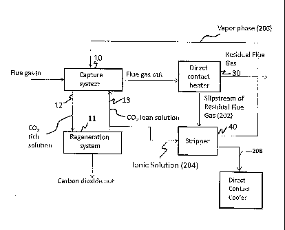
BRIEF DESCRIPTION OF THE FIGURES
[0009] Figure 1 depicts an exemplary liquid gas separation system that
comprises a
carbon dioxide capture system, a regeneration system and an appendix stripper;
and
[0010] Figure 2 depicts a stripping system comprising an appendix
stripper that uses a
blower to introduce flue gases into the bottom of the appendix stripper.
CA 02868947 2014-09-29
WO 2013/144877 PCT/1B2013/052454
3
DETAILED DESCRIPTION
[0011] Disclosed herein is a chilled ammonia process for extracting carbon
dioxide
from a flue gas stream. The method advantageously uses an appendix stripper
that uses a
carbon dioxide depleted residual flue gas stream (hereinafter "residual flue
gas stream") to
strip ammonia and carbon dioxide from ionic solution. The carbon dioxide
depleted residual
flue gas stream is at a lower temperature than steam, which has hitherto been
used in the
appendix stripper.
[0012] Conventional solutions (i.e., previously existing solutions) depend on
sensitive
temperature control of the steam going to the reboiler. Operating experience
has shown that
the composition of the vapor phase is sensitive to the bottoms temperature,
resulting in the
over stripping of ammonia and in ammonia sulfate dissociation.
[0013] The use of the residual flue gas as the stripping medium (in lieu of
steam) in
the appendix stripper avoids the use of high temperatures brought about by the
use of steam
and prevents the dissociation of ammonium sulfate into its acidic components.
This
minimizes degradation of the liquid gas separation system. In addition,
capital and
operational costs associated with the use of steam and the use of the reboiler
are reduced.
[0014] Figure 1 depicts an exemplary liquid gas separation system 4 that
comprises a
carbon dioxide capture system 10 (also known as an absorber), a regeneration
system 11, a
direct contact heater 30 and an appendix stripper 40, all of which are in
fluid communication
with one another. Another exemplary embodiment of a portion of the liquid gas
separation
system is depicted in the Figure 2.
[0015] With reference now to both the Figures 1 and 2, a recycle loop for the
ionic
solution lies between the capture system 10 and the regeneration system 11.
The ionic
solution generally comprises an aqueous solution of ammonia. A portion of the
lean ionic
solution 204 is withdrawn and fed to the appendix stripper 40. In the appendix
stripper, lean
ionic solution is contacted with a residual flue gas stream from the direct
contact heater 30 to
strip light ends in the vapor phase ¨ ammonia and carbon dioxide ¨ from the
lean ionic
solution. In one embodiment, the appendix stripper comprises structured or
random packing
to facilitate mass transfer.
[0016] The capture system 10 captures and removes carbon dioxide from a flue
gas
stream by contacting it with a lean ionic solution 13. The lean ionic solution
(which is so
termed because it is lean in carbon dioxide) extracts carbon dioxide from the
flue gas stream
to form a carbon dioxide rich ionic solution 12 (hereinafter "rich ionic
solution"). A residual
flue gas stream 32 now substantially devoid of carbon dioxide is transported
to a direct
CA 02868947 2014-09-29
WO 2013/144877 PCT/1B2013/052454
4
contact heater 30. A portion of the residual flue gas (a slipstream) is sent
to the appendix
stripper 40 as the stripping medium.
[0017] The appendix stripper 40 is designed to control liquid accumulation in
the
capture system 10 and to maintain an acceptable level of ammonium sulfate in
the ionic
solution. The appendix stripper 40 is arranged in fluid communication with,
and configured
to receive a portion of, the circulating ionic solution stream, separate the
received ionic
solution into an ammonia rich gas phase (a vapor phase (206)) and an ammonia
lean liquid
phase (a liquid phase (208)), and reintroduce the ammonia rich gas phase (206)
into the
capture system 10. In an exemplary embodiment, the ammonia rich gas phase
(206) is
reintroduced into the circulating ionic solution stream via the capture system
10. The
ammonia lean liquid phase (208), consisting mainly of water is removed from
the system.
Ionic solution may be supplied to the appendix stripper 40 passively, e.g., by
means of the
internal pressure of the carbon dioxide removal system.
[0018] The direct contact heater 30 heats the residual flue gas stream for
stack
discharge to the atmosphere. Using the cooler residual flue gas stream as a
stripping
medium, prevents the loss of ammonia from the ionic solution and also
minimizes the
decomposition of the ammonium sulfate into its acidic components.
[0019] The regeneration system 11 is operative to treat the rich ionic
solution 12 at a
temperature and pressure to release carbon dioxide from the rich ionic
solution. The carbon
dioxide may then be sequestered or used for other purposes. The lean ionic
solution 13
produced after the release of the carbon dioxide (from the rich ionic
solution) is then recycled
to the capture system 10. A portion of the lean ionic solution 13 (shown as
the ionic solution
(204) in the Figures 1 and 2) comprising water, ammonia, ammonium sulfate,
carbon dioxide
and derivatives thereof is then discharged to the appendix stripper 40 to
remove the ammonia
lean liquid phase as detailed above.
[0020] The discussion hereinafter pertains only to the Figure 2. Figure 2
displays a
portion of the liquid gas separation system 100 that comprises an appendix
stripper 106. The
flue gases downstream of a power generation system comprises a boiler (not
shown) are
treated in a capture system (not shown) to remove carbon dioxide thereby
producing a
residual flue gas stream 202. A portion of the residual flue gas stream 202
(i.e., the
slipstream) is discharged to the appendix stripper 106 via a direct contact
heater (not shown)
and an optional blower 108. The use of the blower 108 (e.g., a fan) slightly
increases the
pressure of the flue gas stream from the pressure with which it emanates from
the direct
contact heater.
CA 02868947 2014-09-29
WO 2013/144877 PCT/1B2013/052454
[0021] The direct contact heater is used to heat the residual flue gas stream
202 to a
temperature of about 25 to about 50 C, specifically about 30 to about 45 C.
The residual flue
gas stream 202 is used as a replacement for steam as the stripping medium in
the appendix
stripper 40. The residual flue gas stream 202 comprises nitrogen, oxygen and
moisture and is
used as a stripping medium and is introduced into the lower portion of the
appendix stripper
106. The residual flue gas stream is introduced into the appendix stripper 106
at a pressure
around atmospheric pressure.
[0022] A lean ionic solution stream 204 comprising ammonia, ammonium
carbonate,
ammonium bicarbonate and ammonium sulfate from the regenerator is also fed to
the upper
portion of the appendix stripper 106. The lean solution stream 204 is fed
through a
distribution header (not shown) into the appendix stripper where it contacts
the residual flue
gas stream. As a result of the contact between the lean solution stream 204
and the residual
flue gas stream 202, a vapor phase 206 and a liquid phase 208 is formed. The
vapor phase
206 is analogous to the ammonia rich gas phase detailed above and comprises
ammonia
vapor, water vapor, carbon dioxide and nitrogen and is taken off the upper
portion of the
appendix stripper 106. The vapor phase 206 may be recharged to the capture
system. In an
exemplary embodiment, the vapor phase 206 is routed to an injection grid in
the capture
system.
[0023] The bottoms in the appendix stripper 106 comprise the liquid phase 208,
which contains water, ammonium sulfate and a low concentration of ammonia.
This solution
is discharged to a direct contact cooler (not shown) for discharge with other
ammonium
sulfate byproduct streams.
[0024] This system has a number of advantages. By returning the ammonia at a
low
temperature directly to the absorber, a significant energy benefit is achieved
in terms of
sensible heat (lower heat) and latent heat (no steam to condense). The ammonia
stripping
efficiency is greater than about 98%, specifically greater than about 99% and
more
specifically greater than about 99.5%. No steam is used for this process, thus
minimizing or
even eliminating the degradation of ammonium sulfate. No flue gas preheating
is used. The
process is conducted at nominal atmospheric pressure thus reducing costs of
pressurizing the
residual flue gas stream.
[0025] The invention is further illustrated by the following non-limiting
examples.
EXAMPLE
[0026] Example 1
CA 02868947 2014-09-29
WO 2013/144877 PCT/1B2013/052454
6
[0027] This example was conducted to determine the stripping efficiency of a
system
that uses an appendix stripper. The lean solution stream comprising a mixture
of ammonium,
ammonium carbonate, ammonium bicarbonate and ammonium sulfate was introduced
into
the top of the appendix stripper through a distribution header. The ammoniated
solution
contains ammonia ions in a concentration of 7.23 M. The residual flue gas
stream from the
direct contact heater comprising carbon dioxide, nitrogen and moisture is
pressurized by the
blower and introduced into the appendix stripper from the bottom. The residual
flue gas
stream is introduced at the bottom of the appendix stripper at a temperature
of 25 to 50 C.
[0028] The residual flue gas stream and the lean solution stream thus travel
through
the appendix stripper in mutually opposed directions. The interaction between
the flue gas
stream and the lean solution stream results in the formation of a vapor phase
and a liquid
phase (also referred to as "bottoms") in the appendix stripper. The vapor
phase comprises
ammonia vapor, water vapor, carbon dioxide and nitrogen and is removed from
the top of the
stripper. The vapor phase is routed to a typical injection grid in the capture
system.
[0029] The liquid phase comprises water, ammonium sulfate and a low
concentration
of ammonia (0.02 to 0.04 M) and is removed from the bottom of the appendix
stripper and
discharged to a direct contact cooler. The stripping efficiency is higher than
99%. No steam
is required to accomplish this stripping efficiency.
[0030] It will be understood that when an element is referred to as being "on"
another
element, it can be directly on the other element or intervening elements may
be present there
between. In contrast, when an element is referred to as being "directly on"
another element,
there are no intervening elements present. As used herein, the term "and/or"
includes any
and all combinations of one or more of the associated listed items.
[0031] It will be understood that, although the terms "first," "second,"
"third" etc.
may be used herein to describe various elements, components, regions, layers
and/or sections,
these elements, components, regions, layers and/or sections should not be
limited by these
terms. These terms are only used to distinguish one element, component,
region, layer or
section from another element, component, region, layer or section. Thus, "a
first element,"
"component," "region," "layer" or "section" discussed below could be termed a
second
element, component, region, layer or section without departing from the
teachings herein.
[0032] The terminology used herein is for the purpose of describing particular
embodiments only and is not intended to be limiting. As used herein, the
singular forms "a,"
"an" and "the" are intended to include the plural forms as well, unless the
context clearly
indicates otherwise. It will be further understood that the terms "comprises"
and/or
CA 02868947 2014-09-29
WO 2013/144877 PCT/1B2013/052454
7
"comprising," or "includes" and/or "including" when used in this
specification, specify the
presence of stated features, regions, integers, steps, operations, elements,
and/or components,
but do not preclude the presence or addition of one or more other features,
regions, integers,
steps, operations, elements, components, and/or groups thereof.
[0033] Furthermore, relative terms, such as "lower" or "bottom" and "upper" or
"top," may be used herein to describe one element's relationship to another
elements as
illustrated in the Figures. It will be understood that relative terms are
intended to encompass
different orientations of the device in addition to the orientation depicted
in the Figures. For
example, if the device in one of the figures is turned over, elements
described as being on the
"lower" side of other elements would then be oriented on "upper" sides of the
other elements.
The exemplary term "lower," can therefore, encompasses both an orientation of
"lower" and
"upper," depending on the particular orientation of the figure. Similarly, if
the device in one
of the figures is turned over, elements described as "below" or "beneath"
other elements
would then be oriented "above" the other elements. The exemplary terms "below"
or
"beneath" can, therefore, encompass both an orientation of above and below.
[0034] Unless otherwise defined, all terms (including technical and scientific
terms)
used herein have the same meaning as commonly understood by one of ordinary
skill in the
art to which this disclosure belongs. It will be further understood that
terms, such as those
defined in commonly used dictionaries, should be interpreted as having a
meaning that is
consistent with their meaning in the context of the relevant art and the
present disclosure, and
will not be interpreted in an idealized or overly formal sense unless
expressly so defined
herein.
[0035] Exemplary embodiments are described herein with reference to cross
section
illustrations that are schematic illustrations of idealized embodiments. As
such, variations
from the shapes of the illustrations as a result, for example, of
manufacturing techniques
and/or tolerances, are to be expected. Thus, embodiments described herein
should not be
construed as limited to the particular shapes of regions as illustrated herein
but are to include
deviations in shapes that result, for example, from manufacturing. For
example, a region
illustrated or described as flat may, typically, have rough and/or nonlinear
features.
Moreover, sharp angles that are illustrated may be rounded. Thus, the regions
illustrated in
the figures are schematic in nature and their shapes are not intended to
illustrate the precise
shape of a region and are not intended to limit the scope of the present
claims.
[0036] While the invention has been described with reference to exemplary
embodiments, it will be understood by those skilled in the art that various
changes may be
CA 02868947 2014-09-29
WO 2013/144877 PCT/1B2013/052454
8
made and equivalents may be substituted for elements thereof without departing
from the
scope of the invention. In addition, many modifications may be made to adapt a
particular
situation or material to the teachings of the invention without departing from
the essential
scope thereof. Therefore, it is intended that the invention not be limited to
the particular
embodiment disclosed as the best mode contemplated for carrying out this
invention, but that
the invention will include all embodiments falling within the scope of the
appended claims.
[0037] What is claimed is: