Note: Descriptions are shown in the official language in which they were submitted.
CA 02869050 2014-10-28
,
Title of the Invention
[0002] Moment-Resisting Joint and System
Cross-Reference to Related Applications
[0003] The present application claims the right of foreign priority with
respect to
Application No. US60/679,884, filed 05/12/2005, in United Sates of America.
Field of the Invention
[0004] The present invention relates to a non-welded, structural connection
system with
moment resisting capability that can be used in a pony-truss bridge system of
in diverse
areas of architectural design, engineering, fabrication, and field erection
structures using
tubular members.
Background of the Invention
[0005] Transportable and assemblable bridges are known which can provide a
path for
pedestrian, bicycles, light or heavy vehicles, across and over obstacles such
as rivers and
ravines. Some example of previous invention of prefabricated unit construction
modular
bridging systems may be found in U.S. Pat. Nos. 4,912,795 / 5,414,885 /
6,009,586 /
4,965,903/6,308,357 / 6,631,530 and 5,924,152.
[0006] Most of the time, fusion welding is employed to assemble such
structures.
However, it is well known in literature that aluminum fusion welding partially
anneals
the weld zone by creating a heat-affected-zone on the base metal which
decreases its
ultimate and yield strengths (example can be read in Dispersoid-Free Zones in
the Heat-
Affected Zone of Aluminum Alloy Welds--B. C. MEYER, H. DOYEN, D.
1
CA 02869050 2014-10-28
PCT/CA2006/000778
Priority date: 12 May 2005
Pending USPTO: 60/679,884
Revision : -
Date = 2007/11/05
EMANOWSKI, G. TEMPUS, T. HIRSCH, and P. MAYR). The present invention allows
the fabrication of such structure using the full strength of aluminum because
no welding
for the main bearing structure would be required anymore. As an additional
feature, the
invention could allow anodizing, bake paint finished and easy transportation
of all
components to the erection site. The fabrication of all components could also
be made by
numerically controlled technologies that could increase accuracy as well as
minimizing
the fabrication time. Most of these additional features are not always
possible for
conventional aluminum welded structures since large structures request special
transportation or would not fit into anodizing baths or on automated bake
paint lines.
[0007] Another important advantage is that the invention allows all elements
to be joined
quickly together on site with a minimum of fasteners to form a bridge of the
required
length and strength within the overall limitations of the system wether it is
made of
aluminum, steel or other suitable material.
Objects of the Invention
[0008] It is an object of the present invention to provide a mean to build
transportable
bridges which can be easily and readily transported in pieces by, for example,
trucks,
boats, aircrafts or helicopters.
[0009] It is a further object of the present invention to design such bridge
pieces so that
they may be carried or parachuted into the desired location.
[0010] It is yet another object of the present invention to allow for the
bridge to be
assembled as a self-supporting, projecting structure by relatively few people
without
using special equipment.
[0011] The invention can achieve one or more of the following advantages:
2
_
CA 02869050 2014-10-28
'
= Avoiding the creation of a heat-affected-zone for the main bearing
elements;
= No certified welders are required to assemble the structure;
= Very long span possible due to the light weight of aluminum;
= Allowing architectural finishes such as anodizing, bake paint finishes
and others;
= Pre-engineered structures that minimize the engineering design costs;
= Off-the-shelf elements that allow a structure to be shipped within few
working
days compared to weeks or months for a regular welded structure;
= Pre-fabricated elements with numeric controlled technologies reduces
labour costs
and poor accuracy;
= Decreasing assembly costs because the structure can be assembled quickly
with
minimal labour as well as a minimum number of fasteners;
= Ease of transportation (or exportation) allows all elements to be shipped
on
regular bundles or pallets independently of the final size of the complete
structure.
[0012] The invention is especially advantageous for use in the construction of
structures
made from aluminum.
[0013] Other and further objects and advantages of the present invention will
be obvious
upon an understanding of the illustrative embodiments about to be described or
will be
indicated in the appended claims, and various advantages not referred to
herein will occur
to one skilled in the art upon employment of the invention in practice.
Summary of the Invention
[0013A] According to one aspect, the present invention relates to a moment
transferring
assembly, comprising: a) a connector node element having a plurality of
cavities; b) a
plurality of framing members for mounting to the connector node element into
respective
ones of the cavities; c) each framing member being generally elongated and
having an
3
CA 02869050 2014-10-28
end portion insertable into a respective cavity; d) a mechanical fastener for
mounting
between the connector node element and the framing member and capable of being
fastened to maintain the connector node element and the framing member engaged
with
one another; e) wherein the connector node element includes a channel for
receiving
therein an elongated load carrying chord; 1) wherein the mechanical fastener
has a tool
engaging head located for access by a tool through the channel such that when
the
elongated load carrying chord is received in the channel removal of the head
to separate
the framing member from the connector node element is precluded.
[0013B] According to another aspect, the present invention relates to a moment
transferring assembly, comprising: a) a connector node element having a
plurality of
cavities; b) a plurality of framing members for mounting to the connector node
element
into respective ones of the cavities; c) each framing member being generally
elongated
and having an end portion insertable into a respective cavity; d) a mechanical
fastener for
mounting between the connector node element and the framing member and capable
of
being fastened to maintain the connector node element and the framing member
engaged
with one another; e) wherein the connector node element includes a channel for
receiving
therein an elongated load carrying chord; f) wherein the mechanical fastener
has a tool
engaging head and when the elongated load carrying chord is received in the
channel the
tool engaging head is adjacent the load carrying chord such that the
mechanical fastener
is precluded from backing out.
[0013C] According to still another aspect, the present invention relates to a
modular load
bearing lattice structure, comprising: a) a first chord; b) a second chord; c)
a plurality of
connector node elements mounted on the second chord, each connector node
element
comprising: a channel receiving the second chord therein; and a plurality of
cavities; d)
framing members linking the connector node elements to the first chord,
wherein: each
framing member is generally elongated and has an end portion inserted in a
respective
one of the cavities of a respective one of the connector node elements; a
mechanical
fastener is mounted between the framing member and the respective one of
connector
3a
CA 02869050 2014-10-28
node elements and fastened to maintain the framing member and the respective
one of the
connector node elements engaged with one another; and the mechanical fastener
has a
tool engaging head located for access by a tool through the channel of the
respective one
of the connector node elements such that, with the second chord received in
the channel if
the respective one of the connector node elements, removal of the tool
engaging head to
separate the framing member from the respective one of the connector node
elements is
precluded.
[0013D] According to yet another aspect, the present invention relates to a
modular load
bearing lattice structure, comprising: a) a first chord; b) a second chord; c)
a plurality of
connector node elements mounted on the second chord, each connector node
element
comprising: a channel receiving the second chord therein; and a plurality of
cavities; d)
framing members linking the connector node elements to the first chord,
wherein: each
framing member is generally elongated and has an end portion inserted in a
respective
one of the cavities of a respective one of the connector node elements; a
mechanical
fastener is mounted between the framing member and the respective one of
connector
node elements and fastened to maintain the framing member and the respective
one of the
connector node elements engaged with one another; and the mechanical fastener
has a
tool engaging head and, with the elongated second chord received in the
channel of the
respective one of the connector node elements, the tool engaging head is
adjacent the
second chord such that the mechanical fastener is precluded from backing out.
[0013E] According to a further aspect, the present invention relates to a set
of molded
elongated structural members for constructing a structure, each molded
elongated
structural member of the set of molded elongated structural members
comprising: a) an
external wall defining a hollow interior of the molded elongated structural
member; and
b) a core located in the hollow interior and molded with the external wall,
the core
including: i. a fastening portion defining an opening for receiving a threaded
fastener
fastening the molded elongated structural member to an adjacent part of the
structure; and
ii. a plurality of web portions connecting the fastening portion to the
external wall and
3b
CA 02869050 2014-10-28
=
spaced apart from one another so as to partition the hollow interior into a
plurality of
hollow spaces.
[0013F] According to yet a further aspect, the present invention relates to a
structural
system comprising: a) a node connector including a plurality of cavities; and
b) a
plurality of molded elongated structural members for mounting to the node
connector into
respective ones of the cavities, each molded elongated structural member of
the plurality
of molded elongated structural members comprising: i. an external wall
defining a hollow
interior of the molded elongated structural member; and ii. a core located in
the hollow
interior and molded with the external wall, the core including: a fastening
portion
defining an opening for receiving a threaded fastener fastening the molded
elongated
structural member to the node connector; and a plurality of web portions
connecting the
fastening portion to the external wall and spaced apart from one another so as
to partition
the hollow interior into a plurality of hollow spaces.
[0013G] According to still a further aspect, the present invention relates to
a bridge
comprising: a) a first chord; b) a second chord; and c) a plurality of molded
elongated
structural members interconnecting the first chord and the second chord, each
molded
elongated structural member of the plurality of molded elongated structural
members
comprising: i. an external wall defining a hollow interior of the molded
elongated
structural member; and ii. a core located in the hollow interior and molded
with the
external wall, the core including: a fastening portion receiving a threaded
fastener
fastening the molded elongated structural member to the first chord; and a
plurality of
web portions connecting the fastening portion to the external wall and spaced
apart from
one another so as to partition the hollow interior into a plurality of hollow
spaces.
[0013H] According to another aspect, the present invention relates to a set of
molded
elongated structural members for constructing a structure, each molded
elongated
structural member of the set of elongated structural members comprising: a) an
external
wall defining a hollow interior of the molded elongated structural member; and
b) a core
3c
CA 02869050 2014-10-28
located in the hollow interior and molded with the external wall, the core
including a
fastening portion defining an opening for receiving a threaded fastener
fastening the
molded elongated structural member to an adjacent part of the structure, the
hollow
interior of the molded elongated structural member including a hollow space
between the
external wall and the fastening portion.
[00131] According to yet another aspect, the present invention relates to a
set of
elongated structural members for constructing a structure, each elongated
structural
member of the set of elongated structural members being an extrusion and
comprising: a)
an external wall defining a hollow interior of the elongated structural
member; and b) a
core located in the hollow interior of the elongated structural member and
extruded with
the external wall, the core including a fastening portion for receiving a
fastener fastening
the elongated structural member to an adjacent part of the structure, the
hollow interior of
the elongated structural member including a hollow space between the external
wall and
the fastening portion.
[0014] There is, therefore, provided in the practice of this invention a
connection system
with moment resisting capability, a novel framing element and a method of
assembling
same.
[0015] The present invention relates to a novel connection system with moment
resisting
capability being used, but not limited to, in a pony-truss bridge which can be
assembled
from individual prefabricated or off-the-shelf components.
[0016] Such structure may be constructed quickly to meet variation of spans or
widths as
well as to provide temporary or permanent access to all individuals, light
vehicles and
bicycles between two areas of different elevation or across and over obstacles
or may be
used as a walkway system to be cantilevered from the existing bridge
structure, thereby
providing suitable walkway widths on both sides of a bridge without reducing
the width
3d
CA 02869050 2014-10-28
of existing traffic lanes.
[0017] The connection system can be attached to the tension chord of a pony-
truss bridge
to resist bending moment such as required for the top chord stability (top
chord stability
criteria utilizing elastic lateral restraints--TV Galambos, Timoshenko). To
assemble the
connection system, three or more multi-hollow members are slid into female
node
cavities and preferably locked in place utilizing a fastener, usually a bolt,
that goes
through their neutral axis. The framing elements are positioned accurately
into the node's
cavities according to fabrication accuracy which may be done by numeric
controlled
technologies. The framing member attachment or fastener means is preferably
done
within the area of its neutral axis by typically, but not limited to, a bolt
that acts to absorb
the tensile forces exerted on to the system without compromising the node
connection.
Once the member is in place, it can be secured by a bolt, a threaded rod or
any other
means that will keep the member into place ideally, but not limited to, within
the neutral
axis region. The external wall of the element has a friction contact with the
internal side
cavity which will resist the compression forces or bending moments exerted
onto the
element therefore it can transfer such forces or moment to the node without
compromising the node connection.
[0018] A given connection system is comprised of a joint or node and
associated
interlinked members to be used in pony-truss bridges system or any other
applicable
4
CA 02869050 2014-10-28
PCT/CA2006/000778
Priority date: 12 May 2005
Pending USPTO: 60/679,884
Revision: -
Date : 2007/11/05
engineered structures. A preferred embodiment of the connection system employs
custom
aluminum extruded hollow elements and a node and bolts or rods to secure
elements to
the node.
[0019] Pony-truss bridge or other structures may be wholly or partially
constructed using
the moment resisting connectors in accordance with the invention. Such a
structure is
comprised of a plurality of framing elements, joint or node connectors, and
attachment
means.
[0020] To assemble a structure with the use of the invention, some members are
positioned into the node's cavities given at the same time the final alignment
due to the
perfect fit inside the cavity while another member, generally a chord, is
liked onto the
channel's node. Ideally, all members are secured with fasteners while some
have only one
fastener that goes through their neutral axis and another one, generally the
chord, has at
least two bolts that secure it through the node's channel. For ease of
reference, every time
the word cavity is used hereinafter, it is to be understood a cavity with a
specific depth
to confer moment resisting capability. This depth can be determined with
calculation,
benchmark tests or other known means.
[0021] An example of a structure using the invention is a transportable bridge
or other
similar structure having two longitudinal vertical trusses, comprising: plural
bridge
elements connected to each other by rigid nodes on a chord. The structure
includes: a
decking extending across a width of the bridge and having an horizontal
triangular or
Vierendeel truss depending on the lateral forces being acting on the structure
(usually
created by wind loads). Each vertical truss of the structure (main carrying
members)
resists gravity live and dead loads and brings sufficient stiffness to limit
the deflection in
conjunction of acting as a guard-rail. When the invention is being used for a
pony-truss
bridge system both vertical trusses have a bottom chord and an oppositely
disposed top
chord, the lower chord portion of the truss being connected to the
transversals usually
5
CA 02869050 2014-10-28
PCT/CA2006/000778
Priority date: 12 May 2005
Pending USPTO: 60/679,884
Revision: -
Date : 2007/11/05
also made of a multi-hollow beams and multi-hollow diagonal struts by the
rigid node
herein named connection system.
[0022] The bridge vertical trusses, and thus the main load carrying members of
the
bridge, has essentially five different components: the top and bottom chords,
the
diagonals struts and/or vertical posts, the top connector (superior node) and
the bottom
connector (inferior node) which one connect both vertical trusses by
horizontal floor
members. These horizontal members can support what is called stringers located
underneath a decking. The decking can be however made of different type of
material but
preferably, it could be made of a material having a low specific mass, for
example
composites or aluminum. The triangular trusses are dimensioned to reduce their
size and
corresponding weight. Consequently, the decking and the triangular trusses can
be made
so light that eventually the bridge structure could land on floating dock
without the
necessity to add additional buoyancy to it. Eventually the reduced weight of
the
individual components could allow the bridge to be manually assembled and
carried by
relatively few people.
[0023] When assembled, the bridge has a half-through shape, and consists
essentially of
longitudinally extending main support vertical trusses, and a decking.
[0024] The connection system being used as a moment resisting connector for
the half-
through bridge structure that can be eventually used to construct footbridges,
golf course
bridges, skywalks, overpasses, vehicular access bridges, bicycle path bridge,
trail bridges,
recreational bridges, walkways and so.
[0025] Further, freeway overpasses and underpasses built in the last decades
frequently
lack adequate walkways in situations where pedestrians or bicycles are
permitted. In
many communities, such barriers prevent pedestrian/bicycles access between
neighborhoods, schools, and employment centers. In such cases the invention
could serve
6
CA 02869050 2014-10-28
PCT/CA2006/000778
Priority date: 12 May 2005
Pending USPTO: 60/679,884
Revision : -
Date : 2007/11/05
to construct bridges that can be placed on the side of existing narrow bridges
to give
better access to the communities.
[0026] To eliminate excessive free play between the connected components when
the
bridge is assembled, the triangular trusses are interlockingly connected with
each other.
The interlocking connection includes at least one fastener that goes through
the neutral
axis of the diagonal and/or vertical struts, transversal beams as well as a
minimum of
fasteners to hold the connector to the bottom chord of the truss. Fasteners
that secure the
struts to the connector act in tension while fasteners that hold the connector
to the chords
act in shear. Further, the top chord is linked to the diagonal and/or vertical
struts with the
mean of a pin connection working in shear.
[0027] A lubricant can be disposed at the interface of the connection of
framing elements
and node connectors to allow an easier disassembling if the bridge is
temporarily
installed.
[0028] The invention will be described below in greater detail in connection
with
embodiments thereof that are illustrated in the drawing figures.
[0029] The features of the present invention which are believed to be novel
are set forth
with particularity in the appended claims.
Brief Description of the Drawings
[0030] A preferred embodiment of the present invention will be described in
greater
detail below with reference to the following drawings, in which:
[0031] Fig. 1 is a perspective view of a fully assembled modular bridge in
accordance
with the present invention.
7
_ õ
CA 02869050 2014-10-28
'
[0032] Fig. 2 is a perspective view of the main carrying members of the bridge
shown in
Fig. 1 prior to installation of floor boards, fencing and stringers;
[0033] Fig. 3 is an exploded perspective view of the bridge understructure
shown in Fig.
2;
[0034] Fig. 4 is an exploded perspective view of the bridge shown in Fig. 1
including
floor boards, fencing and stringers;
[0035] Fig. 5 is a perspective view of a splice in the bridge of Fig. 2;
[0036] Fig. 6 is a exploded perspective view of the connection system with
moment
resisting capability shown in all previous figures (Figs. 1, 2, 3, 4 & 5);
[0037] Fig. 7 is an elevation view of the connection system shown in Fig. 6
when fully
assembled;
[0038] Fig. 8 is a section view along lines A-A in Fig. 7 when fully
assembled;
[0039] Fig. 9 is a section view along lines B-B in Fig. 7 when fully
assembled;
[0040] Fig. 10 is a section view of along lines C-C in Fig. 9 when fully
assembled;
[0041] Fig. 11 is a exploded perspective view of the compression chord
connector shown
in Figs. 1, 2, 3, 4 & 5;
[0042] Fig. 12 a section view of the superior connector shown in Fig. 11 when
fully
assembled;
[0043] Fig. 13 is a section view along lines D-D in Fig. 12 when fully
assembled;
8
CA 02869050 2014-10-28
,
. ,
. '
[0044] Fig. 14 is an elevation view of the inferior node connector with moment
resisting
capabilities;
[0045] Fig. 15 is an elevation view of the superior node connector;
[0046] Fig. 16 is a section view of the diagonal/vertical struts and
transversals;
[0047] Fig. 17 is an alternative for the inferior connector element. It is
therefore possible
that the struts to be made of a hollow section, usually circular, and the
tension forces can
be taken by a rod that is independently located near the strut neutral axis;
[0048] Fig. 18 is a section view along lines E-E in Fig. 17 when fully
assembled;
[0049] Fig. 19 is another alternative for the inferior connector element. It
is therefore
possible that the struts to be made of a hollow section, usually circular, and
the tension
forces can be taken by an insert located inside the hollow section; and
[0050] Fig. 20 is a section view along lines F-F in Fig. 19 when fully
assembled.
Detailed Description of the Preferred Embodiment
[0051] Turning to Fig. 1, a modular pedestrian bridge 1 is shown comprising a
plurality
of individual elements connected to each other by the mean of node connectors
4 and 7.
Fencing 20 connect to the vertical trusses on the inside as shown or
eventually on the
outside. A decking 21, or eventually floor boards, is placed on top of the
stringers (not
shown) and acts as a floor to be walked on. Ends of the bridge, when
installed, are
connected to respective end footings (not shown) via respective anchors (not
shown).
9
CA 02869050 2014-10-28
PCT/CA2006/000778
Priority date: 12 May 2005
Pending USPTO: 60/679,884
Revision: -
Date : 2007/11/05
[0052] The modular sections of fencing 20 may be fabricated to any suitable
length.
Typical sections contemplated are 5 feet, 10 feet, 15 or 20 feet in length.
[0053] Fig. 2 shows the bridge in Fig. 1 prior to installation of the decking
and stringers.
As can be seen from Fig. 2, both vertical trusses are linked to each other via
a plurality of
transversals 3 and diagonals 5 extending there between.
[0054] Fig. 3 illustrates an exploded view of the main bearing structure
comprising a
plurality of linear elements such as two tension chords 8, two compression
chords 1, a
plurality of diagonals 2, transversals 3, floor diagonals 5 all connected to
each other by
the mean of top node connectors 7 and bottom node connectors 4.
[0055] Next, as shown with reference to Fig. 4, longitudinal stringers 22 are
placed and
secured on top of the transversals 3. A decking is secured to the stringers
via fasteners
(not shown). A fencing system 20 (optional) can be attached to the vertical
main load
carrying trusses.
[0056] Turning to Fig. 5, successive ones of the vertical trusses are shown
comprising top
and bottom chord members 1 and 8 connected via splices 30 and 31. Diagonal
members 2
provide additional support.
[0057] The bottom node connector is shown in greater detail with reference to
Fig. 6
comprising diagonals 2, tension chord 8, floor diagonals 5, transversals beams
3 and a
node connector 4 that have the ability to transfer bending moments. The
diagonals and
transversals are inserted into corresponding cavities thereby 41 at the distal
ends of the
diagonals and transversals members 2 and 3. Ideally, the diagonals and
transversals have
tapered ends for insertion into corresponding ones of the cavities. Their ends
can be
milled, turned, swaged or bring to this particular shape by the mean of any
way. The
cavities however could be or not to be of a similar corresponding shape
depending on
temporary or permanent use of the structure (vertical or tapered inside wall
of cavities).
CA 02869050 2014-10-28
The best way to secure such diagonals and transversals inside the node
connector could
be done by the use of a bolt that is screwed inside the internal region 42 of
the multi-
hollow cavity extruded tube as shown in Fig. 16 and as shown in greater detail
with
reference to Figs. 8 and 10. The node connector is attached to the tension
chord by a pair
of bolts 34 and nuts 35 through two like pairs of holes adapted to align the
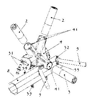
node 4 and the
chord 8. Both floor diagonals attach to the node connector with bolts 32 and
nuts 33.
[0058] The node connector form a solid and extremely stable connection between
the
hollow tubing chord members 8, the transversal beam 3 and the diagonals 2 for
maintaining structural integrity throughout the chord members 8, thereby
overcoming
lateral stability problems inherent in half through (pony) bridge. As shown
with reference
to Fig. 6, bolts that are used to secure diagonals and transversals are hidden
so they
cannot be unscrewed while the node is attached to the chord providing
additional safety
against thief or sabotage. Additionally, anti thief nuts can be used instead
of regular nuts
to secure the node connector to the chord 35. The resulting connector is in a
visually
attractive appearance.
[0059] Turning now to Figs. 7, 8, 9 and 10, the first figure is an elevation
view from the
inside of the bridge. Element 3 is the transversal hollow beam and elements 5
are the
diagonal bracings to resist any horizontal loading act on the projected area
of the bridge
structure. Elements 2 are the diagonals that support the compression chord
(not shown).
They mainly resist tension and compression forces but they also transfer some
bending
moment to the floor beams as well as they transfer torsion to the tension
chord 8 since
they stabilize the compression chord which one tend to buckle. Fig. 8 shows a
view along
lines A-A in Fig. 7. As it can be seen a fastener 36, generally a bolt,
secures the floor
beam 3 into the node 4 cavity. Bolt 34 secure the node 4 to the tension chord
8. Fig. 9
shows a view along lines B-B in Fig. 7. Fig. 10 shows a view along lines C-C
in Fig. 9.
Once again we find two fasteners, generally bolts, to secure both diagonal
members 2
into the node 4 cavities.
11
CA 02869050 2014-10-28
[0060] As shown best with reference to Fig. 11, the exploded view of the
compression
node connector shows two diagonals 2, two superior node connectors 7, a
compression
chord 1 and their associated fasteners 36, 37 and 38, generally bolts. The
diagonals 2 are
linked to the superior nodes generally by the mean of one bolt 36 screwed into
their
neutral axis. The superior node connectors are however linked to the
compression chord
by the mean of a bolt 37 that fits into a hole in the compression chord 1. The
bolt 37 is
secured in place with a nut 38 or preferably with an antitheft nut (not
shown).
[0061] Fig. 12 shows a sectional view from the compression chord 1. It is
therefore
acknowledge that the bolt 37 works in shear while the fasteners (not shown)
that secure
the diagonal 2 on the superior node 7 works in tension.
[0062] Fig. 13 shows a view along lines D-D in Fig. 12. As it is shown,
fasteners,
generally bolts 36, secure the diagonals 2 on the superior node 7. A fastener
37 goes
through a hole in the compression chord 1.
[0063] Fig. 14 shows the moment resisting node connector 4 while Fig. 15 shows
the
superior node connector which one are generally liked to a multi-hollow
extruded shape
as it is shown in Fig. 16. Even if the cylindrical framing element 2, 3 has
been shown
having a circular section, it is to be noted that the section of the framing
element could
have any other suitable section such as, for example curved section (e.g.
ellipsoidal) or
polygonal section (e.g. square, triangular or else).
[0064] Fig. 17 shows a possible alternative to the use of a multi-hollow
section shown in
Fig. 16. It is therefore possible to use, but not preferred, a regular hollow
shape that could
be secured into the node cavities by the mean of a rod partially or completely
threaded.
Fig. 18 shows a view along lines E-E in Fig. 17. A rod 39 can run on or near
the neutral
axis of a tube. A nut 40 can give a pre-tension to maintain the tube inside
the cavity with
adequate pressure.
12
CA 02869050 2014-10-28
[0065] In addition to the alternative shown in Fig. 17, Fig. 19 shows another
alternative
that could be possible, but not necessary desired, as it could allow the
element 9 (a
hollow section) to be secured into place with the mean of a threaded insert 44
as shown in
Fig. 20 that would fit the inside of the element 9. The insert 44 could be
maintained
inside the element 9 by the mean of welding or by any other mean.
[0066] Fig. 20 is a view along lines F-F in Fig. 19 and it shows the insert
that could be
achieved to secure in place the element 9 into place with a fastener 43,
generally a bolt.
[0067] Thus, in final assembly the center load of diagonals or verticals are
supported
equally by horizontal or tapered wall when the elements work in compression or
by the
mean of the fasteners, generally bolts, when the diagonals or verticals work
in tension.
The transversals however transfer their moment to the node with the friction
applied
along the internal walls.
[0068] Accordingly, a maximum dimension of transversals 3 and diagonals 2 may
be
accommodated irrespective of the width and length of the bridge. By way of
contrast,
known prior art transversals or diagonals connections require multiple welds,
generally
fillet weld type, which are not desired since it weakens the base material
when aluminum
is employed for such structure.
[0069] Accordingly, an important aspect of the present invention is the
improved
mechanical properties because of avoiding welding of the main structural
members. The
connector acts as a rigid node able to carry and transfer tension,
compression, torsional
and bending moments provided by usually only one interlocking fastener running
through
the neutral axis of diagonals/verticals and transversals.
[0070] Preferably, all metallic structural components of the pedestrian bridge
in Fig. 1 in
accordance with present invention are made of aluminum with the possibility to
hard
13
CA 02869050 2014-10-28
anodize each individual element, for forming an aesthetically pleasing and
scratch
resistant surface.
[0071] Other embodiments and variations of the present invention are
contemplated.
[0072] For example, the connector of the present invention may be
advantageously
applied to virtually any structures using standard or custom hollow tubing. To
that end,
the inventive moment resisting connector could be used in such diverse
applications as
furniture construction, building construction, fencing, bridges, towers, flag
post bases,
gantry of motorway etc., any of which may be fabricated from stainless steel,
plastic,
steel or other suitable material.
[0073] Furthermore, whereas the preferred embodiment of the tapered end
element which
may usually be milled, swaged or turned by numeric controlled technologies, it
is
contemplated that end portions of the elements 2 and 3 may also be strait.
[0074] As a further alternative, the node configuration may be fabricated via
specialized
machining tools from a solid block or cast from metal or eventually made of
composites.
[0075] Moreover, whereas the preferred embodiment discloses a structural
connection for
use with multi-hollow cross-sectional elements 2 and 3 in Fig. 16, it is
contemplated that
the cooperating element and cavity aspect of the present invention may be
applied
equally to hollow tubing sections having square, circular or other cross-
section.
[0076] All such embodiments or variations are believed to be within a sphere
and scope
of the present invention as defined by the claims appended hereto.
[0077] Although preferred embodiments of the invention have been described in
detail
herein and illustrated in the accompanying figures, it is to be understood
that the
invention is not limited to these precise embodiments and that various changes
and
14
CA 02869050 2014-10-28
, .
modifications may be affected therein. For example, the node resisting joint
and system
of the invention may be used to construct roofs and other structures using
nodes to join
elongated members.