Note: Descriptions are shown in the official language in which they were submitted.
CA 02869230 2014-09-30
WO 2014/078308 PCT/US2013/069678
PURIFICATION ARRANGEMENTS AND METHODS
FOR GAS PIPELINE SYSTEMS
Disclosure of the Invention
[0001] Natural gas and other gases transmitted through pipeline systems may
carry many
types of particulates, including liquid droplets and/or solid particles. The
gas may be the
source of the particulates. For example, gas entering the pipeline system from
a gas
treatment facility after it has been extracted from a well may still be laden
with particulates.
Or the particulates may be generated within the pipeline system itself For
example, solid
particles may be generated by corrosion and abrasion within the pipeline
system. Liquid
droplets may arise from condensation or as residues of liquid cleaners for the
pipeline system.
Many of these particulates are harmful to the components of the pipeline
system and the
personnel who operate and service the pipeline system. For example, the gas
may carry black
powder, a general term used to describe a host corrosion-related particulate
contaminants,
that can be erosive, toxic, and/or chemically reactive with air, i. e.,
pyrophoric.
[0002] The present invention relates to purification arrangements and
methods for
removing particulates from gas flowing through the pipeline system.
Embodiments of the
invention may include a pressure vessel having an inlet and an outlet
connected to the
pipeline system. The pressure vessel may contain at least two purification
assemblies, and
the gas may be directed through the pressure vessel, where the purification
assemblies
remove particulates from the gas.
[0003] A wide variety of purification assemblies may be used to remove the
particulates.
For example, one or more of the purification assemblies may comprise a filter
assembly.
Each filter assembly may include one or more filter elements, and each filter
element may
include a porous filter medium. As the gas flows through the pressure vessel,
it passes
through the filter medium, and the particulates carried by the gas are trapped
on the surface of
and/or within the filter medium. Alternatively or additionally, one or more of
the purification
assemblies may comprise a separator assembly. Each separator assembly may
include one or
more separators which remove particulates from the gas without the use of a
porous filter
medium. For example, a separator may slow the velocity of the gas and allow
the particulates
to settle from the gas, or a separator may deflect the particulates from the
principal gas flow
stream, causing the gas and the particulates to separate from one another. In
any event, the
purification assemblies remove a significant portion of the particulates, and
gas leaving the
pressure vessel has significantly fewer particulates than gas entering the
pressure vessel.
1
CA 02869230 2014-09-30
WO 2014/078308 PCT/US2013/069678
Summary of the Invention
[0004] In accordance with one aspect of the invention, purification
arrangements for a
gas pipeline system may comprise a pressure vessel, a modular filter assembly,
and a modular
separator assembly. The pressure vessel may include an interior, a gas inlet,
and a gas outlet
and may define a gas flow path through the interior of the pressure vessel
between the gas
inlet and the gas outlet. The pressure vessel may have an elongate
configuration including a
horizontal axis and first and second axial ends. The pressure vessel may also
have a cover
moveably mounted to the first axial end, the cover being movable between a
first position and
a second position. In the first position, the cover may be sealed to the first
axial end of the
pressure vessel, and in the second position the cover may provide an opening
at the first axial
end of the pressure vessel. The modular filter assembly may be removeably
located in the
gas flow path in the interior of the pressure vessel and may comprise a
plurality of filter
elements. Each filter element may have a filter medium positioned across the
gas flow path
to filter particulates from gas flowing through the filter element. The
modular separator
assembly may be removeably located in the gas flow path in the interior of the
pressure
vessel between modular filter assembly and the gas inlet. The modular
separator assembly
may have one or more separators positioned in the gas flow path to remove
particulates from
gas flowing along the gas flow path. The modular filter assembly and the
modular separator
assembly may each be removeable from and moveable into the interior of the
pressure vessel
as an integral unit. The modular separator assembly may be removable from and
moveable
into the pressure vessel via the opening at the first axial end of the
pressure vessel when the
cover is in the second position.
[0005] In accordance with another aspect of the invention, methods for
removing
particulates from a gas flowing in a gas pipeline system may comprise
establishing a flow of
gas through the interior of a horizontal pressure vessel from a gas inlet to a
gas outlet,
including directing the gas through one or more separators of a modular
separator assembly
and through one or more filter elements of a modular filter assembly to remove
particulates
from the gas. The methods may also comprise terminating the flow of gas
through the
pressure vessel; removing the modular separator assembly as an integral unit
from the
pressure vessel through an opening in a first axial end of the pressure
vessel; and installing a
cleaned or new modular separator assembly as an integral unit into the
pressure vessel
through the opening in the first axial end of the pressure vessel. The methods
may further
comprise restablishing a flow of gas through the interior of the pressure
vessel from the gas
2
CA 02869230 2014-09-30
WO 2014/078308 PCT/US2013/069678
inlet to the gas outlet and through the new or cleaned modular separator
assembly in the
interior of the pressure vessel.
[0006] Purification arrangements and methods embodying one or more aspects
of the
invention have many advantageous features, including features that are highly
effective for
removing particulates from the gas. For example, by including both a filter
assembly and a
separator assembly, purification arrangements and methods embodying the
invention remove
most particulates, especially black powder, so the gas returning to the
pipeline system from
the pressure vessel has far fewer particulates, e.g., may be largely free of
solid particles and
liquid droplets, compared to the gas entering the pressure vessel from the
pipeline system.
Further, the modular separator assembly, as well as the modular filter
assembly, may quickly
and easily be removed and installed in the horizontal pressure vessel. Each
assembly is
modular in that it can be removed from, and installed into, the horizontal
pressure vessel as
an integral unit. For example, once the modular separator assembly becomes
loaded with
particulates, it may be removed from the horizontal pressure vessel in a very
short period of
time as an integral unit through the opening in the first axial end of the
pressure vessel when
the cover is open. Similarly, a cleaned or new modular separator assembly may
be installed
in the horizontal pressure vessel even more quickly as an integral unit
through the opening in
the first axial end of the pressure vessel. For many embodiments, a modular
filter assembly
loaded with particulates and a cleaned or new modular filter assembly may also
be quickly
and easily removed/installed as an integral unit, for example, through the
same opening in the
first axial end of the horizontal pressure vessel. The modular nature of the
filter and
separator assemblies thus greatly reduces the downtime required to remove and
replace each
assembly, thereby enhancing the efficiency of the purification process.
Further, the
purification assemblies, e.g., the modular filter assembly and the modular
separator assembly,
may be adjusted or restructured to accommodate varying gas flow conditions in
the pipeline
without modification of the pressure vessel.
Brief Description of the Drawings
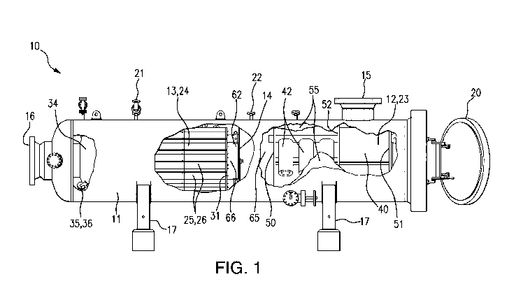
[0007] Fig. 1 is a side view of purification arrangement with portions of
the pressure
vessel and shell cut away.
[0008] Fig. 2 is an oblique view of a filter assembly.
[0009] Figs. 3a and 3b are oblique top and bottom views of a separator
assembly.
[0010] Fig. 4 is an oblique view of a casing for the separator assembly of
Fig. 3.
[0011] Fig. 5 is an exploded oblique view of an openable/closeable barrier.
3
CA 02869230 2014-09-30
WO 2014/078308
PCT/US2013/069678
Detailed Description of Embodiments of the Invention
[0012]
Purification arrangements embodying the invention may be configured in a wide
variety of different ways. For example, the purification arrangement 10 shown
in Fig. 1 may
comprise a pressure vessel 11 and two or more purification assemblies 12, 13
located in the
interior of the pressure vessel 11. The pressure vessel 11 may have a gas
inlet 15 and a gas
outlet 16 coupled to a gas pipeline system (not shown) and may define a gas
flow path
through the interior of the pressure vessel between the gas inlet 15 and the
gas outlet 16. The
purification assemblies 12, 13, one a modular separator assembly and the other
a modular
filter assembly, may be positioned in the gas flow path between the gas inlet
15 and the gas
outlet 16. Natural gas or any other gas passing through the gas pipeline
system is directed
through the pressure vessel 11 from the gas inlet 15 through the purification
assemblies 12,
13 to the gas outlet 16. A significant portion of the particulates, e.g.,
almost all solid particles
and most of the liquid droplets, entrained in the gas as it enters the gas
inlet 15 is removed by
the purification assemblies 12, 13, so the gas leaving the pressure vessel 11
is largely free of
particulates.
[0013] The
pressure vessel may be configured in any of numerous ways. For example,
the pressure vessel may have a configuration similar to a scraper
trap/launcher vessel used to
service the interior of the pipeline. The pressure vessel may have an
elongate, generally
cylindrical structure and the axis may extend horizontally, or it may extend
vertically or at
any angle between horizontal and vertical. The pressure vessel may be formed
as a unitary
structure or in a plurality of sections joined together in a fluid-tight
manner. Further, the
pressure vessel may be constructed to withstand the design pressures and
temperatures
appropriate for the pipelines of the pipeline system. For example, for many
natural gas
pipeline systems, the design pressure may be in the range from about 30 barg
or less to about
75 barg or more, e.g., about 60 barg, and the design temperature may be in the
range from
about minus 40 C to about 100 C, e.g., about 70 C. For many embodiments,
the pressure
vessel may be formed from a metal and is quite large and heavy. The gas inlet
and the gas
outlet of the pressure vessel may be on opposite axial ends of the vessel, or
one may be on an
end and the other may be on the side of the vessel, or both may be on the side
of the vessel
facing in the same or different directions. In addition to the gas inlet and
the gas outlet, a
variety of other ports may be provided at various locations on the vessel,
including ports for
pressure protection, purging, flooding, depressurization, and/or draining and
for pressure drop
and level control. Further, the pressure vessel may include one or more
hatches or other
4
CA 02869230 2014-09-30
WO 2014/078308 PCT/US2013/069678
covers on the ends or side of the pressure vessel to allow access to the
interior for service
personnel and/or equipment, including removal and installation of the
purification
assemblies. In the embodiment of Fig. 1, the pressure vessel 11 may be
oriented horizontally
and supported by two or more stands 17 and may include a gas outlet 16 at one
axial end of
the pressure vessel 11, a gas inlet 15 in the side of the pressure vessel 11,
e.g., at the top and
nearer the other axial end, and a cover such as a quick opening hatch 20
hinged at the other
axial end of the pressure vessel 11. The hatch 20 may be large enough to swing
open and
provide access along the entire inner diameter of the pressure vessel 11,
facilitating
installation and removal of the purification assemblies. Alternatively, any
other cover may
be bolted to the end of the pressure vessel, again providing access along the
entire inner
diameter when the cover is removed and facilitating removal and installation
of one or more
of the purification assemblies. The pressure vessel 11 may also be provided
with one or more
purge gas inlets 21 and one or more gas discharge outlets 22 communicating
between the
interior and exterior of the pressure vessel 11.
[0014] The purification assemblies may be configured in a wide variety of
ways to
remove particulates, including liquid particulates and/or solid particulates,
entrained in the
gas. For example, depending on the specific type of particulates present in
the gas of the
pipeline system, at least one of the purification assemblies in the pressure
vessel may be a
modular filter assembly and at least one of the purification assemblies in the
pressure vessel
may be a modular separator assembly. For many pipeline systems, black powder
may be a
typical particulate entrained in the gas. Black powder is a general term used
to describe a
host of corrosion related contaminants in pipelines that transport natural
gas, hydrocarbon
condensates, liquefied petroleum gas, and other gases. The chemical and
physical
composition of black powder may vary significantly. It can be a dry powder, a
liquid
suspension, and/or an intermediate sticky sludge. The dry powder may include
iron oxides,
iron sulfides, and iron carbonates and may be fine, even submicron in size.
For example,
about 70% of the dry black powder particles may be about 10 microns or less in
size, and the
total loading may be in the range of about 5 to 30 grams/MMSCF during normal
operation of
the pipeline, although after a scraping operation the total loading may
increase by a factor of
up to 20 or more. Binder material present in the pipelines, e.g., parafins,
asphaltenes, glycols,
and/or lubricants, may hold some of the black powder particles together to
form larger
agglomerates. Additional solids, e.g., sand and/or silt, frequently accompany
the black
powder entrained in the gas. Consequently, for many of the embodiments, one of
the
purification assemblies, e.g., the most downstream purification assembly in
the pressure
CA 02869230 2014-09-30
WO 2014/078308 PCT/US2013/069678
vessel, may be a modular filter assembly arranged to remove finer
particulates, and another
purification assembly, e.g., the most upstream purification assembly, may be a
modular
separator assembly arranged to remove liquid particulates and/or larger solid
particulates and
agglomerates. For example, in the purification arrangement 10 shown in Fig. 1,
the
purification assembly 12 coupled more closely to the gas inlet 15 may be a
modular separator
assembly 23 and the purification assembly 13 coupled more closely to the gas
outlet 16 may
be a modular filter assembly 24. A modular assembly is an assembly that can be
removed
from or moved into the pressure vessel as an integral unit.
[0015] The modular filter assembly may be configured in any of numerous
ways and may
include one or more filter elements. For many embodiments, the modular filter
assembly 24
may comprise a filter bundle assembly having an array of filter elements 25,
as shown in Fig.
2. The filter elements may have any of a wide variety of shapes and sizes. For
example, each
filter element 25 may have a hollow, generally cylindrical shape, may include
a blind end and
an open end fluidly communicating with the interior of the hollow element, and
may be
arranged for gas flow outside-in or inside-out through the element. The filter
elements 25
may include a wide variety of porous filter media 26 for removing particulates
from the gas.
The porous filter medium may, for example, include a porous metal medium, a
porous
ceramic medium, or a porous polymeric medium and may, for example, be in the
form of a
spirally wound or pleated membrane or sheet, e.g., a fibrous sheet, or a
hollow, cylindrical
mass, e.g., a fibrous mass. Further, the filter medium may have any of a
variety of removal
ratings. For embodiments targeting black powder, the filter medium may
comprise a high-
efficiency, high-dirt capacity, tapered-pore, absolute-rated gas depth filter
medium.
Examples of filter elements that are particularly effective for removing black
powder include
filter elements rated 0.3 micron in gas and available under the trade
designation Coreless
from Pall Corporation of Port Washington, New York USA.
[0016] The modular filter assembly 24 may also include a frame 30 for
supporting the
filter assembly, including the array of filter elements 25, as an integral
unit. The frame may
be configured in any of numerous ways and may support the array for gas flow
outside-in or
inside-out through the hollow filter elements. For example, the frame 30 may
support the
array for outside-in gas flow and may include a tube sheet 31 at the end of
the array nearer
the gas outlet 16, a support plate 32 closer to, or at, the opposite end of
the array, and one or
more struts 33 that connect the tube sheet 31 and the support plate 32. The
tube sheet 31 and
the support plate 32 may have a shape that generally conforms to the cross-
sectional shape of
the interior of the pressure vessel and a dimension, e.g., an outer diameter,
that closely
6
CA 02869230 2014-09-30
WO 2014/078308 PCT/US2013/069678
corresponds to the inner diameter of the pressure vessel. The tube sheet 31
may have a
plurality of openings, and the open end of each filter element 25 may be
sealed to an opening
in the tube sheet 31, either directly or via a stand-off tube, as shown in
Fig. 2. The tube sheet
31 thus defines an unfiltered region of the filter assembly around the filter
elements 25 on one
side of the tube sheet 31 and a filtrate region on the opposite side of the
tube sheet 31. The
filtrate side of the tube sheet 31 may be sealed to a header 34 which, in
turn, may be sealed to
the gas outlet 16 of the pressure vessel 11. For example, the header 34 may
taper to an open
outlet end that may be sealed to the gas outlet 16. Alternatively, the tube
sheet may be sealed
to the interior of the pressure vessel, e.g., along the outer edge of the tube
sheet. The support
plate 32, which may be connected to the filter elements 25, for example, at
the blind ends of
the filter elements 25, may also have a plurality of openings, allowing the
unfiltered gas to
flow from the gas inlet 15 along the exterior of the filter elements 25.
[0017] The modular filter assembly may include one or more additional
components. For
example, the filter assembly may or may not further include a shell
surrounding the array of
filter elements and/or a transit mechanism facilitating the removal and
installation of the
modular filter assembly within the pressure vessel. In the embodiment shown in
Fig. 2, the
filter assembly 24 may not include a shell but may include a transit mechanism
35. The
transit mechanism may be configured in any of numerous ways including, for
example, as
slides on the modular filter assembly and/or rails along the interior of the
pressure vessel. In
Fig. 2, the transit mechanism 35 may comprise a plurality of wheels 36, e.g.,
spring loaded
wheels, connected to the frame 30 and/or the header 34 and distributed around
the modular
filter assembly 24, allowing the modular filter assembly 24 to be quickly and
conveniently
rolled out of and into the interior of the pressure vessel 11.
[0018] The modular separator assembly may be configured in any of numerous
ways and
may include one or more separators, including, for example, one or more
inertial separators.
For many embodiments, the modular separator assembly may comprise a multi-
stage
separator assembly, and at least one stage may include any type of centrifugal
or dynamic
separator. One of many different examples of a modular separator assembly is
the two-stage
separator assembly 23 shown in Fig. 3 The first stage may include an impact
separator, e.g.,
a downwardly angled impact plate 40, directly in the gas flow path from the
gas inlet 15 and
a large settling region 41 below the impact plate 40. The second stage may
include one or
more higher efficiency separators 42, e.g., a baffl( of cyclone separators 42
supported by a top
plate 43. For some embodiments, the cyclone separators 42 may have a cut off
of down to 8
microns or less at rated gas flow and a cut off of down to 10 microns or less
at 50% of rated
7
CA 02869230 2014-09-30
WO 2014/078308 PCT/US2013/069678
gas flow. Any number of cyclone separators may be provided, e.g., four or
more, six or
more, eight or more, or ten or more, and the cyclone separators may be
variously configured.
In the embodiment of Fig. 3, each cyclone separator 42 may include an outer
can 44 mounted
around an inner can 45. The outer can 44 may be closed at the inlet end, e.g.,
by the top plate
43, and open at the lower outlet end, and the inner can 45 may be open at both
the inlet and
outlet ends, the outlet end of the inner can opening through the top plate 43.
The axes of the
cyclone separators may be oriented parallel to, perpendicular to, or at any
angle to the axis of
the pressure vessel. In the illustrated embodiment, the axes are generally
perpendicular to the
axis of the pressure vessel 11. Additional traps may be arranged at and/or
below the lower
outlet of the outer can to enhance the retention of particulates.
[0019] The modular separator assembly may also include a frame supporting
the multi-
stage separators as an integral unit in the pressure vessel, and the frame may
be configured in
any of numerous ways. For example, the frame may comprise a plurality of
support plates
50-52 connected by one or more struts 53, as well as the top plate 43 and the
impact plate 40.
A downstream support plate 50 may be positioned at the outlet end of the
separator assembly
23, an upstream support plate 51 maybe positioned at the opposite end of the
separator
assembly 23, and an intermediate support plate 52 may be positioned between
the upstream
and downstream support plates 50, 51. Each support plate 50-52 may have a
dimension, e.g.,
an outer diameter, that closely corresponds to the inner diameter of the
pressure vessel 11,
enabling the support plates 50-52 to fit closely against the pressure vessel
11 and inhibit
bypass of any gas around the entire separator assembly 23 or any of the stages
of the
separator assembly 23. For some embodiments, one or more of the support plates
50-52 may
be sealed to the pressure vessel 11. The first stage of the separator assembly
23 may be
defined between the upstream support plate 51 and the intermediate support
plate 52, while
the second stage may be defined between the intermediate support plate 52 and
the
downstream support plate 50. An opening in the intermediate support plate 52
beneath the
angled impact plate 40 may open into a duct 54 that extends below the top
plate 43, allowing
gas to flow from the first stage into the second stage. The duct 54 may feed
the gas to each
cyclone separator 42, for example, through an inlet opening in the side of the
outer can 44
near the inlet end. An opening in the downstream support plate 50 above the
top plate 43
allows gas to exit the second stage of the modular separator assembly 23 and
enter the
modular filter assembly 24.
[0020] The modular separator assembly may include one or more additional
components.
For example, for many embodiments the modular separator assembly may include a
shell
8
CA 02869230 2014-09-30
WO 2014/078308 PCT/US2013/069678
mounted to one or more of the separators and/or stages of the separator
assembly to contain
the particulates removed by the separators. The shell may be variously
configured and may
or may not be connected and/or sealed to the remainder of the separation
assembly. For
example, the shell 55 may be generally cylindrical and open on both ends and
may surround
one or more or all of the separators 40-42 or stages. The shell 55 may be
dimensioned to fit
within the interior of the pressure vessel 11 and around the separators and
support plates 50-
52 of the separator assembly 23. For example, the shell 55 may be dimensioned
to closely
correspond to the inner diameter of the pressure vessel 11 and the outer
diameter of the
support plates 50-52, enabling the shell 55 to inhibit bypass of any gas
between the pressure
vessel 11 and the shell 55 or between the shell 55 and the support plates 50-
52. For many
embodiments, the shell 55 may be sealed to the support plates 50-52 in any
suitable manner,
e.g., permanently or releasably, to contain any particulates removed from the
gas by the
modular separator assembly 23. For example, the shell 55 may be welded to the
outer rims of
the separator plates 50-52 to form a liquid-tight container containing the
solids and liquids
removed from the gas by the modular separator assembly 23. The shell 55 may
have a
significant liquid and/or solids holding capacity which allows all of the
particulates removed
by the modular separator assembly 23 over an extended period, even after
scraping
operations, to be conveniently and safely stored within the shell 55. The
shell may have one
or more openings. For example, the shell 55 may include an inlet opening 57 in
the side, e.g.,
at the top, of the shell 55 that fluidly communicates with the gas inlet 15 in
the pressure
vessel 11, allowing gas to flow through the gas inlet 15 into the first stage
of the separator
assembly 23. The inlet opening 57 in the shell 55 may fit closely against the
gas inlet 15
and/or may be sealed to the gas inlet 15 to prevent bypass of gas around the
modular
separator assembly 23. Other openings in the shell 55 may include sealable
side openings 58
that facilitate emptying and cleaning of the interior of the shell 55 and
another top opening 59
that allows the shell to be filled with water and/or any other suitable
inhibitor. For many
embodiments, the shell 55 need not be a pressure vessel capable of
withstanding the
difference in pressure between the interior and the exterior of the pressure
vessel 11. Instead,
the shell 55 may be formed from a much lighter gauge material, e.g., a lighter
gauge metal,
that can contain solids and liquids removed by the modular separator assembly
23.
[0021] The modular separator assembly may or may not further include a
transit
mechanism facilitating removal and insertion of the separator assembly within
the pressure
vessel or the shell. The transit mechanism may be configured in any of
numerous ways,
including, for example, as slides on the frame or the shell of the filter
assembly and/or rails
9
CA 02869230 2014-09-30
WO 2014/078308 PCT/US2013/069678
along the pressure vessel. In the illustrated embodiment, the transit
mechanism may comprise
a plurality of wheels 56. For embodiments without a shell, the transit
mechanism, e.g., the
wheels, may be distributed around the frame of the separator assembly and may
be arranged
to move, e.g., roll, along the inner periphery of the pressure vessel 11 in a
manner similar to
the filter assembly wheels 36. The modular separator assembly may then be
quickly and
easily rolled along the pressure vessel to remove and install the modular
separator assembly,
e.g., via the open hatch. Once it is installed, the modular separator assembly
may be locked in
place in the pressure vessel by a locking mechanism. For embodiments with a
shell 55, a
transit mechanism, e.g., the wheels 56, may be attached to the frame of the
separator assembly
23 and may be arranged to move along the interior of the shell 55. For
example, outside of
the pressure vessel 11 the separators 40, 42 and the frame of the separator
assembly 23 may
be moved, e.g., rolled, along the interior of the shell 55 and permanently or
removably fixed
in place in the shell 55, for example, by welding the support plates 50-52 to
the shell 55.
Then the entire modular separator assembly 23 including the shell 55 may be
moved as an
integral unit into the pressure vessel 11, e.g., through the open hatch 20,
and fixed in place in
any suitable manner with the gas inlet 15 of the pressure vessel 11 fluidly
communicating
with the inlet opening 57 in the shell 55. The shell may further include a
transit mechanism,
e.g., wheels, to facilitate movement along the pressure vessel, or the shell
with the remainder
of the separator assembly inside may be guided along the pressure vessel, for
example, by a
push/pull table similar to the push/pull tables used for scrapers.
[0022] The purification arrangement may include one or more additional
components.
For example, for some embodiments the purification arrangement 10 may include
an
openable/closeable barrier 14 positioned in the interior of the pressure
vessel 11 between the
modular separator and filter assemblies 23, 24. The openable/closeable barrier
may be
configured in a variety of ways to alternately provide fluid communication
between the
modular filter assembly and the modular separator assembly and fluidly isolate
the modular
assemblies. For example, the barrier 14 may comprise a pair of coaxially
mounted plates 60,
61, at least one of the plates 61 being rotatable. For many embodiments, one
plate 60 may be
stationary and the other plate 61 may be rotatable. The plates 60, 61 may have
a shape that
generally conforms to the cross-sectional shape of the interior of the
pressure vessel 11 and a
dimension, e.g., an outer diameter, that closely corresponds to the inner
diameter of the
pressure vessel 11, providing a close fit between the outer edge of the plates
60, 61 and the
interior of the pressure vessel 11 to inhibit gas flow when the barrier 14 is
closed. The plates
60, 61 may extend generally perpendicular to the axis of the pressure vessel
11 and may or
CA 02869230 2014-09-30
WO 2014/078308 PCT/US2013/069678
may not be sealed to the pressure vessel 11. Each plate 60, 61 may have one or
more
apertures extending around a significant portion, e.g., about 50% or less, of
the circumference
of the plate 60, 61, the remainder of the plate 60, 61 being imperforate.
Alternatively, one of
the plates 60, 61, e.g., a rotatable plate 61, may be a partial plate having
only an imperforate
portion large enough to obstruct the aperture on the other plate 60 in the
closed position. The
barrier 14 may be movable between an open position and a closed position. For
example, at
least one of the plates 61 may rotate with respect to the other plate 60
between the open
position and the closed position. In the open position, the aperture(s) of the
plates 60, 61 are
aligned and unobstructed, the barrier 14 is open, and gas may flow through the
open barrier
14 between the modular assemblies 23, 24. For many embodiments, the
imperforate portion
of the rotatable plate(s) may be oriented gravitationally below the
aperture(s). The greater
weight of the imperforate portion may "lock" the barrier in the open position
during normal
operation when gas flows between the purification assemblies. Alternatively or
additionally,
the plates 60, 61 may be locked in the open position by a locking mechanism
(not shown). In
the closed position, the imperforate portions of the plates 60, 61 obstruct
the apertures of the
plates 60, 61, the barrier 14 is closed, and the modular assemblies 23, 24 are
fluidly isolated
from one another. The plates 60, 61 may be sealed to one another or may be
positioned
sufficiently close to one another to substantially inhibit gas flow through
the obstructed
apertures of the closed barrier.
[0023] The barrier 14 may be mounted in the gas flow path between the
modular
separator and filter assemblies in a wide variety of ways. For example, the
barrier 14 may
include a mount 62 for supporting the barrier 14 in the gas flow path between
the modular
assemblies 23, 24. The mount 62 may be variously configured and the plates 60,
61 may be
supported by the mount 62 in a variety of ways, e.g., rotatably supported. The
mount may be
attached to a variety of structures to support the barrier in the interior of
the pressure vessel.
For some embodiments, the mount may be attached to the pressure vessel itself
For
example, the mount may be attached, e.g., removably attached, to the interior
of the pressure
vessel, supporting the barrier between the modular filter assembly and the
modular separator
assembly. For other embodiments, the mount may be attached to the modular
separator
assembly. For example, the mount may be attached to the struts or the
downstream support
plate of the frame or to the shell of the separator assembly, supporting the
barrier just beyond
and downstream of the separator assembly. For still other embodiments, the
mount may be
attached directly to the modular filter assembly 24. For example, the mount 62
may be
11
CA 02869230 2014-09-30
WO 2014/078308 PCT/US2013/069678
attached to the frame 30 of the filter assembly 24, e.g., the support plate 32
and/or the struts
33, supporting the barrier 14 just behind and upstream of the filter assembly
24.
[0024] Methods for removing particulates from a gas flowing in a gas
pipeline system
may be embodied in a wide variety of ways. For example, during normal
operation a flow of
gas may be established through the pipeline system and through the pressure
vessel 11
connected to the pipeline. As the gas flows along the gas flow path through
the interior of the
pressure vessel 11, the gas is directed through the gas inlet 15, the modular
separator
assembly 23 and the modular filter assembly 24 before exiting the pressure
vessel 11 via the
gas outlet 16. As the gas flows through the modular separator and filter
assemblies 23, 24, a
significant portion of the particulates, both liquid and solids, is removed
from the gas by the
modular assemblies 23, 24. The upstream modular separator assembly 23 may
remove liquid
and larger solids particulates and the downstream modular filter assembly 24
may remove
finer solids particulates. This arrangement of a modular separator assembly 23
upstream and
a modular filter assembly 24 downstream in the pressure vessel 11 is
particularly effective for
removing black powder from the gas.
[0025] As shown in Fig. 1, gas may enter the pressure vessel 11 and pass
along the gas
flow path first through the modular separator assembly 23 and then through the
modular filter
assembly 24. As the gas passes through the separator assembly 23, it may be
first directed
through the first stage of the separator assembly to remove liquid and larger
solids
particulates and then through the second stage to remove additional liquids
and finer solids
particulates. For example, gas may pass from the gas inlet 15 directly to the
first stage,
impinging against an impact separator, e.g., the angled impact plate 40.
Liquid particulates
may coalesce along the impact plate 40 and then flow to the bottom of the
first stage. The
larger solids particulates may be deflected by the impact plate 40 to the side
and then fall to
the bottom of the first stage. After moving quickly past the edges of the
angled impact plate
40, the gas may slow in the larger settling region 41 below the angled impact
plate 41,
allowing additional particulates to settle to the bottom of the first stage.
Particulates removed
in the first stage may be contained between the upstream support plate 51 and
the
intermediate support plate 52.
[0026] The gas may then enter the second stage from the settling region 41
of the first
stage, for example, passing through an aperture located closely under the apex
of the angled
impact plate 40 and into the duct 54 of the second stage. From the duct 54,
the gas may enter
a cyclone separator 42, for example, through an inlet opening in the side of
each outer can 44,
where the gas and remaining liquid and solids particulates are swirled within
the outer can 44
12
CA 02869230 2014-09-30
WO 2014/078308 PCT/US2013/069678
toward the outlet end of the can 44. Liquid and solids particulates are
deflected from the
principal gas flow stream by the cyclonic movement of the gas in the outer can
44 and fall to
the bottom of the second stage through the outlet end of the outer can 44.
Additional traps
(not shown) beneath the outer cans may enhance the retention of liquid and
solid particulates
between the intermediate and downstream support plates 52, 50. The gas may
pass from the
outlet end of the outer can 44 and into the inlet end of the inner can 45,
where it may pass
along the inner can 45 and through the outlet end of the inner can 45 into the
space above the
top plate 43. From the space above the top plate 43, the gas, substantially
depleted in
particulates, may exit the modular separation assembly 23, for example,
through the opening
in the downstream support plate 50 above the top plate 43. Particulates
removed in the
second stage may be contained between the intermediate support plate 52 and
the
downstream support plate 50.
[0027] For embodiments having a shell 55 around the separators or stages of
the modular
separation assembly 23, e.g., the first and/or second stages of the separation
assembly 23, the
removed liquid and solid particulates are conveniently and safely contained in
the modular
separation assembly 23 by the shell 55 and isolated from the pressure vessel
11. For
example, the particulates removed in the first stage may be contained between
the upstream
support plate 51 and the intermediate support plate 52 by the shell 55. The
particulates
removed in the second stage may be contained between the intermediate support
plate 52 and
the downstream support plate 50 by the shell 55. For embodiments without a
shell, the
removed particulates may be contained in the separation assembly by the
support plates and
the pressure vessel.
[0028] From the modular separator assembly 23, the gas may flow along the
gas flow
path to the modular filter assembly 24. For embodiments having an
openable/closable barrier
14, the gas may flow between the modular assemblies 23, 24 through an open
barrier 14. For
example, the gas may flow through the aligned apertures in the plates 60, 61
of the open
barrier 14 between the modular separator assembly 23 and the modular filter
assembly 24
with little or no pressure drop. For embodiments without an openable/closable
barrier, the
gas may flow directly to the modular filter assembly.
[0029] The gas may then pass along the gas flow path through the modular
filter
assembly 24, where any finer particulates remaining in the gas may be removed
by the filter
medium 26. For example, for embodiments arranged for outside-in flow through
the filter
elements 25, the gas may flow into the unfiltered region along the exterior of
the filter
elements 25. The gas then passes outside-in through the porous filter medium
26 of each
13
CA 02869230 2014-09-30
WO 2014/078308 PCT/US2013/069678
filter element 25, where the finer particulates are removed by the filter
medium 26, and into
the interior of the hollow filter element 25. From the interiors of the filter
elements 25, the
filtered gas may pass to the gas outlet 16 of the pressure vessel 11
substantially free of liquid
and solids particulates. For example, the gas may pass along the interiors of
the filter
elements 25 through the apertures in the tube sheet 31 into the header 34 and
through the
header 34 to the gas outlet 16.
[0030] After an extended period of time, one or both of the modular
separator assembly
23 and the modular filter assembly 24 may become loaded with particulates.
Various
sensors, e.g., pressure sensors and/or weight sensors, associated with the
modular assemblies
12, 13 may provide an indication that a design parameter, e.g., the pressure
drop across or the
particulate weight within the modular assembly, has been exceeded. Gas flow
through the
pressure vessel 11 may then be terminated. For example, the pipeline system
may be shut
down or the purification arrangement 10 may be bypassed or taken off line in
favor of a
parallel purification arrangement 10. Upon termination of the gas flow one or
both of the
modular separator and filter assemblies 23, 24 may be serviced, e.g., cleaned
and/or replaced.
[0031] The modular structure of the separator assembly, as well as the
filter assembly,
greatly facilitates removal and replacement. After the modular separator
assembly becomes
loaded with particulates, the pressure vessel may be opened and the modular
separator
assembly, including at least the frame and the separators, may be quickly and
easily removed
from the pressure vessel as an integral unit. For example, the pressure vessel
11 may be
opened by removing the cover, e.g., swinging open the hatch 20 at the first
axial end of the
horizontal pressure vessel 11. The opening provided when the cover is removed
may be large
enough to accommodate removal of the entire modular separator assembly 23 as a
single
integral unit through the first axial end of the pressure vessel. The modular
separator
assembly 23 may be removed, for example, via a push/pull table and/or a
transit mechanism.
Because the modular separator assembly 23 is removed as a single integral
unit, the
downtime required to extract the modular separator assembly from the pressure
vessel 11 is
far less than the downtime required to disassemble a separator assembly within
the pressure
vessel and remove it piece-by-piece.
[0032] For embodiments having a shell 55, the shell 55 of the modular
separator
assembly 23 also facilitates servicing of the purification arrangement 10.
Many particulates,
including black powder, may be toxic and/or may be chemically reactive, e.g.,
pyrophoric,
when exposed to air and, therefore, present a serious safety hazard to the
service personnel.
The shell 55 collects and contains the particulates removed by the separators
40, 42 and
14
CA 02869230 2014-09-30
WO 2014/078308 PCT/US2013/069678
isolates the service personnel from many of the hazards of these particulates.
For example, in
the illustrated embodiment, when the pressure vessel 11 is opened, e.g., by
swinging the
hatch 20 open, and the modular separator assembly 23 is removed through the
open hatch 20,
all of the collected liquid and solid particulates contained within the shell
55 are removed
with the modular separator assembly 23 and are isolated from the service
personnel. To even
further ensure the safety of the service personnel, the shell may be filled
with water and/or
any other suitable inhibitor. For example, water may dilute the liquid
contaminants in the
shell and prevent any solid contaminants in the shell from reacting with air.
The water may
be supplied to the shell 55 through a water inlet in the pressure vessel 11
and the top opening
59 in the shell 55 before the modular separator assembly 23 is removed.
[0033] In addition to protecting the service personnel, the shell 55 of the
modular
separator assembly 23 further reduces the downtime required for removing a
separator
assembly 23 fully loaded with particulates and replacing it with a cleaned/new
modular
separator assembly 23 empty of particulates. Not only does the shell 55
isolate the
particulates from the service personnel, it also isolates the particulates
from the pressure
vessel 11. When the loaded modular separator assembly 23 with all of the
removed
particulates contained within the shell 55 is removed, the pressure vessel
remains relatively
clean, requiring far less time to clean the interior of the pressure vessel 11
in the vicinity of
the removed modular separator assembly 23 and install the cleaned/new modular
separator
assembly 23.
[0034] For embodiments having an openable/closeable barrier, service
personnel may be
further protected by the openable/closeable barrier 14. For example, after the
gas flow is
terminated, the open barrier may be closed, isolating the modular separator
and filter
assemblies from one another and allowing at least one of the modular
assemblies e.g., the
modular separator assembly 23, to be serviced without exposing the service
personnel to the
particulates in the other assembly, e.g., the modular filter assembly 24. For
example, the
hatch 20 of the pressure vessel 11 may be opened and the open barrier 14 may
be moved to
the closed position in any of a variety of ways. For example, one of the
modular assemblies,
e.g., the modular separator assembly 23, may have a hollow guide 63 which
extends through
the separator assembly 23 and allows a tool 64, e.g., an elongate T-bar, to be
coupled to the
open barrier 14 to move it to the closed position. For some embodiments, the
tool 64 may
have a fitting on one end that engages the rotatable plate 61 of the barrier
14 and rotates the
plate 61 until the imperforate portions of the plates 61, 62 obstruct the
apertures in the plates
61, 62, closing the barrier 14. The closed barrier 14 defines first and second
isolated
CA 02869230 2014-09-30
WO 2014/078308 PCT/US2013/069678
chambers 65, 66 within the pressure vessel 11 around the modular separator and
filter
assemblies 23, 24, respectively, allowing the service personnel to service one
of the modular
assemblies 12, 13 free of the risks from the particulates in the other modular
assembly 13, 12.
[0035] For many embodiments, the service personnel may be even further
protected by
flooding one or both of the first and second chambers 65, 66 with an inert
gas, e.g., nitrogen.
For some embodiments, before the hatch 20 is opened, the entire pressure
vessel 11, the first
and second chambers 65, 66, or at least the second chamber 66 may be flooded
with the inert
gas via an inert gas inlet in the pressure vessel 11. The hatch 20 may then be
opened and the
barrier 14 may be moved to the closed position, maintaining the inert gas in
the second
chamber 66 around the filter elements 25 of the modular filter assembly 24.
Additionally, a
small flow of inert gas may be directed into the second chamber 66 to maintain
a small
positive pressure of inert gas in the second chamber 66 while barrier 14 is
closed and the
modular separator assembly 23 is removed and/or serviced. Maintaining the
inert gas around
the modular filter assembly 24 ensures that the fine particulates removed by
the filter
assembly 24 are not exposed to air and subject to the possibility of a
pyrophoric reaction.
[0036] If the modular filter assembly 24 is not in need of servicing, the
region of the
pressure vessel 11 containing the modular separator assembly 23 may be
cleaned, a task
made much easier and faster if the modular separator assembly 23 includes a
shell 55
containing the removed particalutes. A cleaned/new modular separator assembly
23, with or
without a shell, may then be installed in the pressure vessel 11, for example,
through the open
hatch 20 in the pressure vessel 11, e.g., via a transit mechanism and/or
push/pull table. The
modular separator assembly 23 may be installed quickly and easily as a single
integral unit,
further reducing downtime for many reasons similar to those previously
described. For
embodiments having an openable/closeable barrier 14, the closed barrier 14 may
be opened,
either before or after the cleaned/new modular separator assembly is
installed. For example,
a cleaned/new modular separator assembly 23 with a shell 55 may be installed
in the pressure
vessel 11. The T-bar 65 may then be inserted through the guide 63 and engaged
with the
rotatable plate 61, and the plate 61 may be rotated until the apertures in the
plates 60, 61 are
aligned, opening the barrier 14 for normal operation. The cover, e.g., the
hatch 20, may be
closed, and gas flow may again be established through the purification
arrangement 10.
[0037] If the modular filter assembly 24 is also in need of servicing, it
too may be
removed from the pressure vessel 11. For some embodiments, the pressure vessel
may
include a separate opening, e.g., a separate hatch or cover, for removing the
modular filter
assembly, allowing the modular filter assembly to be removed before or at the
same time as
16
CA 02869230 2014-09-30
WO 2014/078308 PCT/US2013/069678
the modular separator assembly. In the illustrated embodiment, the modular
filter assembly
24 may be removed from the pressure vessel 11 after the modular separator
assembly 23
through the same opening, e.g., the hatch 20, as the modular separator
assembly 23. For
embodiments in which an openable/closeable barrier is attached directly to the
pressure
vessel, the barrier and/or the barrier mount may be removed from the pressure
vessel before
the modular filter assembly follows the modular separator assembly through the
hatch. For
embodiments in which the barrier 14 is attached to the modular separator or
filter assembly
23, 24 or no barrier is provided, the modular filter assembly 24 may be
quickly and easily
removed as an integral unit from the pressure vessel 11 for cleaning or
replacement in a
variety of ways, similar to those previously described with respect to the
modular separator
assembly 23. In the illustrated embodiment, the modular filter assembly 24 may
be
disengaged from the gas outlet 16 of the pressure vessel 11, for example, by
disengaging the
header 34 from the gas outlet 16. The modular filter assembly, including at
least the frame
and the array of filter elements, may then be extracted from the pressure
vessel as a single
integral unit. For example, the opening provided when the cover is removed may
be large
enough to accommodate removal of the entire modular filter assembly 24, for
example,
through the first axial end of the pressure vessel by means of a push/pull
table and/or a transit
mechanism. For embodiments with a transit mechanism, e.g., the wheels 36, the
modular
filter assembly 24 may be quickly and easily rolled along the pressure vessel
11, e.g., through
the open hatch 20. Again, because the modular filter assembly 24 is removed as
a single
integral unit, the downtime required to extract the modular filter assembly 24
from the
pressure vessel 11 is far less than the downtime required to disassemble a
filter assembly
within the pressure vessel and remove the filter assembly piece-by-piece. The
barrier 14 may
be removed from the pressure vessel 11, for example, along with the modular
filter assembly
24. The individual filter elements 25 may be cleaned or replaced.
Alternatively, an entirely
new filter assembly 24, including new filter elements 25, with or without a
barrier 14, may
replace the spent modular filter assembly 24.
[0038] Once the pressure vessel 11 is empty, it may be cleaned and a
cleaned/new
modular filter assembly 24 may be installed in the pressure vessel 11 as an
integral unit. For
example, the cleaned/new modular filter assembly 24, with or without an
attached barrier 14,
may be moved into the pressure vessel 11 through the open axial end and along
the pressure
vessel 11 and fitted into sealed engagement with the gas outlet 16 at the
opposite axial end of
the pressure vessel 11. For embodiments with a transit mechanism, e.g., the
wheels 36, the
modular filter assembly 24 may be quickly and easily rolled toward the gas
outlet 16 until the
17
CA 02869230 2014-09-30
WO 2014/078308 PCT/US2013/069678
header 34 engages and is sealed to the gas inlet 16. The modular filter
assembly 24 may be
installed quickly and easily as a single integral unit, further reducing the
downtime as
previously described.
[0039] Before or after the cleaned/new modular filter assembly 24 is
installed, any barrier
14 may be moved to the open position. The cleaned/new modular separator
assembly 23 may
then be installed as a single integral unit as previously described. The
cover, e.g., the hatch
20, may be closed. And a gas flow may again be established through the
purification
arrangement 10, including the modular separator assembly 23 and the modular
filter
assembly 24.
[0040] Although the invention has been disclosed in the embodiments
previously
described and illustrated, the invention is not limited to those embodiments.
For instance,
one or more features of an embodiment may be eliminated or modified, one or
more features
of one embodiment may be combined with one or more features of other
embodiments, or
embodiments with very different features may be envisioned without departing
from the
scope of the invention. For example, for some embodiments the
openable/closeable barrier
may comprise a single plate including one section hinged to another section.
The hinged
section may be moved between a closed position and an open position. In the
closed
position, the two sections of the plate may be co-planar and the plate may
have a shape that
closely fits across the cross section of the pressure vessel, inhibiting gas
flow and isolating
the modular separator and filter assemblies. In the open section, the hinged
sections may
extend at an angle to one another, creating an aperture through which gas may
flow between
the modular separator and filter assemblies. A tool similar to the T-bar may
be used to open
and close the hinged barrier. For some embodiments, the barrier may comprise a
shuttered or
louvered plate. The shutter(s) or louver(s) may be moved to an open or closed
position in a
variety of ways, including for example, as previously described with respect
to the T-bar.
Alternatively, the shutter(s) or louver(s) may be biased toward a closed
position, e.g., by
springs, but forced to the open position, for example, when the modular
separator assembly is
inserted in the pressure vessel. For example, a member on the modular
separator assembly
may contact the barrier and force the shutter(s) or louver(s) open when the
modular separator
assembly is properly positioned in the pressure vessel.
[0041] For some embodiments, the array of filter elements of the modular
filter assembly
may be arranged for gas flow inside-out. The tube sheet may be positioned at
the end of the
array closest to the barrier and may be sealed to the pressure vessel or to a
housing
surrounding the array of filter elements. The open ends of the filter elements
may be sealed
18
CA 02869230 2014-09-30
WO 2014/078308 PCT/US2013/069678
to the apertures in the tube sheet, while the support plate may be located at
or near the
opposite end of the array. Gas flowing through the open barrier may pass into
the interiors of
the hollow filter elements through the apertures in the tube sheet and then
pass inside-out
through the filter medium of the filter elements, where the finer particulates
are removed, to
the exterior of the filter elements. From the exterior of the filter elements,
the gas may pass
to the gas outlet of the pressure vessel.
[0042] The present invention thus encompasses innumerable embodiments and
is not
restricted to the particular embodiments that have been described,
illustrated, and/or
suggested herein. Rather, the present invention includes all embodiments and
modifications
that may fall within the scope of the claims.
[0043] The use of the terms "a" and "an" and "the" and "at least one" and
similar
referents in the context of describing the invention (especially in the
context of the following
claims) are to be construed to cover both the singular and the plural, unless
otherwise
indicated herein or clearly contradicted by context. The use of the term "at
least one"
followed by a list of one or more items (for example, "at least one of A and
B") is to be
construed to mean one item selected from the listed items (A or B) or any
combination of two
or more of the listed items (A and B), unless otherwise indicated herein or
clearly
contradicted by context. The terms "comprising," "having," "including," and
"containing"
are to be construed as open-ended terms (i.e., meaning "including, but not
limited to,") unless
otherwise noted. Recitation of ranges of values herein are merely intended to
serve as a
shorthand method of referring individually to each separate value falling
within the range,
unless otherwise indicated herein, and each separate value is incorporated
into the
specification as if it were individually recited herein. All methods described
herein can be
performed in any suitable order unless otherwise indicated herein or otherwise
clearly
contradicted by context. The use of any and all examples, or exemplary
language (e.g., "such
as") provided herein, is intended merely to better illuminate the invention
and does not pose a
limitation on the scope of the invention unless otherwise claimed. No language
in the
specification should be construed as indicating any non-claimed element as
essential to the
practice of the invention.
[0044] Preferred embodiments of this invention are described herein,
including the best
mode known to the inventors for carrying out the invention. Variations of
those preferred
embodiments may become apparent to those of ordinary skill in the art upon
reading the
foregoing description. The inventors expect skilled artisans to employ such
variations as
appropriate, and the inventors intend for the invention to be practiced
otherwise than as
19
CA 02869230 2014-09-30
WO 2014/078308
PCT/US2013/069678
specifically described herein. Accordingly, this invention includes all
modifications and
equivalents of the subject matter recited in the claims appended hereto as
permitted by
applicable law. Moreover, any combination of the above-described elements in
all possible
variations thereof is encompassed by the invention unless otherwise indicated
herein or
otherwise clearly contradicted by context.