Note: Descriptions are shown in the official language in which they were submitted.
CA 02869590 2014-10-03
WO 2013/150462
PCT/1B2013/052659
1
A BLASTING CARTRIDGE
FIELD OF THE INVENTION
This invention relates to rock breaking and more specifically to cartridges
used for breaking rock.
The term "rock" as used herein covers natural rock and also includes
concrete or similar structures that are to be broken up.
BACKGROUND TO THE INVENTION
Traditional methods of blasting or breaking rock in quarries and mines make
use of high energy explosives, often referred to as detonating explosives.
High energy explosives crush and pulverise the rock which can then be
removed for either retrieving the sought after mineral within the rock or for
disposal of the rock.
The problem with detonating explosives is that the ignition of the explosive
is
followed by a violent shockwave which may cause rock fragments to be
projected from the explosion site. The projected rock fragments pose a great
risk to mine workers, thus commonly requiring a large area surrounding the
blasting site to be cleared. Furthermore, the pulverisation of the rock may
create a thick cloud of dust to surround the blasting site, making it
impossible
to work at the site for extended periods of time.
The problems associated with the traditional methods of blasting or breaking
rock resulted in the development of rock breaking explosives commonly
referred to as non-detonating explosives. Non-detonating explosives function
by containing and directing rapidly expanding gases within and against the
rock, thereby causing the rock to break without the violent shock wave and
pulverisation of the rock.
CA 02869590 2014-10-03
WO 2013/150462
PCT/1B2013/052659
2
Non-detonating explosives are used by drilling boreholes into the rock,
inserting non-detonating explosive cartridges containing a gas generating
compound, commonly a propellant, into the boreholes and igniting the
cartridges. Prior to ignition of the cartridge, the borehole must be stemmed
by
packing particulate material, usually sand, into the borehole after insertion
of
the cartridge. The packed particulate material keeps the gases created by the
cartridge within the borehole once the cartridge has been ignited resulting in
high pressure being created within the borehole.
A drawback of non-detonating explosives is that adequate stemming of the
borehole is of utmost importance, failure of which may cause some of the gas
to escape thereby reducing the pressure exerted onto the rock and causing
the cartridge to be less effective. Furthermore, stemming of boreholes that
run at a downward slope may be difficult thus often being very time
consuming to achieve. Also, stemming material needs to be transported to
the blasting site.
A self-stemming cartridge is proposed in United States Patent No. 8,342,095.
One embodiment of the cartridge disclosed in the patent has a sheath which
is tapered radially inwardly at one end and which houses a gas generating
compound and a cone. The patent discloses that the cone is forced in the
direction of the taper upon ignition of the gas generating compound and
forces the sheath outwardly, thereby stemming the borehole.
Drawbacks of the disclosed cartridge include the cartridge having a plug at
one end which will be ejected from the cartridge prior to stemming, thus
causing the stemming operation to stop and the cartridge to be ejected from
the borehole without breaking any of the rock.
Furthermore, the sheath is of a solid construction. This will permit gas to
escape about the periphery of the cone when the sheath flexes outwardly
CA 02869590 2014-10-03
WO 2013/150462
PCT/1B2013/052659
3
after ignition and from the gas pressure within the cartridge. It is thus
highly
unlikely that the cone will operate to expand the sheath. Also, such flexing
will cause the development of empty pockets within the sheath into which the
gas can move, thus causing a drop in pressure within the cartridge and
resulting in a cessation of combustion of the gas generating compound.
A further disadvantage of the cartridge disclosed in US 8,342,095 is that the
sheath is a solid tube and thus unlikely to expand sufficiently to stem the
hole. Also, the detonator cord runs between cone and sheath creating a gap
which will permit gas to escape and thus prevent proper working of the
cartridge during manufacture and handling. The gap will also permit the
propellant to leak out of the cartridge. Furthermore, the detonator must be
inserted into the cartridge before it can be filled with propellant. This will
create an inherently dangerous situation during assembly as there is a
possibility of the detonator igniting the propellant during assembly.
There is no evidence of the cartridges proposed by US 8,342,095 being
commercially available and the applicant believes this to be a result of these
not being capable of functioning for the reasons given above.
In this specification, "propellant" shall have its widest meaning and include
any suitable gas producing material, and "igniter" shall mean any device
capable of causing the propellant to produce gas.
SUMMARY OF THE INVENTION
In accordance with this invention there is provided a cartridge comprising a
receptacle for holding a propellant therein and having an open end with a
stemming device secured to the open end to form a substantially closed
container, the stemming device being operable to result in radial expansion
thereof and having a static member secured to the receptacle and a piston
movable, at least partially within the container, relative to the static
member
CA 02869590 2014-10-03
WO 2013/150462
PCT/1B2013/052659
4
and the receptacle, and configured such that ignition of the propellant causes
movement of the piston to operate the stemming device and cause radial
expansion thereof before the receptacle ruptures.
Further features of the invention provide for an igniter to be secured within
the stemming device with an operating cord extending therethrough; for the
igniter to be preferably located in a socket in the piston; for the stemming
device to be shaped to provide a sliding fit within a borehole; and for the
receptacle to be cylindrical.
Still further features of the invention provide for the receptacle to be made
of
a plastics material; for the piston to be partly located within the
receptacle; for
the part of the piston located within the receptacle to provide a sliding fit
within the receptacle.
Yet further features of the invention provide for the static member to be
secured over the open end of the receptacle; for the static member to provide
a snap fit over the receptacle; for the static member to have a plurality of
holes therein for receiving buttons on the receptacle; alternately for the
static
member to provide a screw fit on the receptacle.
Further features of the invention provide for a nozzle to extend from the
piston at the end of the piston that is located within the receptacle; the
nozzle
being radially inwardly stepped from the end of the piston; and for the nozzle
to operatively extend into the propellant held within the receptacle.
Still further features of the invention provide for the piston and static
member
to have cooperating bearing surfaces, at least one, preferably both, of which
is tapered such that relative movement causes radially outward expansion of
either the static member or the piston.
CA 02869590 2014-10-03
WO 2013/150462
PCT/1B2013/052659
Yet further features of the invention provide for a stemming device to be
secured to opposite ends of a tubular receptacle; for either or both stemming
devices to have an igniter associated therewith; and for the stemming
devices to be of the same or different configuration to each other.
According to one aspect of the invention the static member has a tapered
bore and at least one longitudinal slit therein to permit radial expansion
thereof.
Further according to this aspect of the invention the static member has a
plurality of circumferentially spaced slits, each slit extending substantially
the
length of the tapered bore.
According to a further embodiment of the invention the static member of the
stemming device has a tubular body with a number of ports therein and an
anchor member associated with each port such that movement of the piston
causes radially outward displacement of each anchor member; for each
anchor member to have a lug which extends centrally from one side of a
panel, each lug providing a complementary fit within a port and the panels
configured to extend over a part of the outer surface of the body; for the
ports
to be elongate and extend longitudinally along the body near its free end; for
the end of the piston engaging the lugs to be tapered; and for the free end of
each lug to have a complementary taper to the piston.
The invention also provides a piston for a cartridge substantially as defined
above, the piston having a cylindrical section providing a sliding fit within
a
tubular receptacle and a tapered section which is movable within an
expansion sleeve to cause radial expansion thereof, with a bore extending
substantially axially through the piston and a nozzle extending from the end
of the piston locatable within the receptacle.
CA 02869590 2014-10-03
WO 2013/150462
PCT/1B2013/052659
6
BRIEF DESCRIPTION OF THE DRAWINGS
The invention will now be described, by way of example only with reference
to the accompanying representations in which:
Figure 1 illustrates a side elevation of a cartridge according to a
first
embodiment of the invention;
Figure 2 illustrates a longitudinal section of the cartridge illustrated
in
Figure 1;
Figure 3 illustrates a side elevation of the receptacle of the cartridge
illustrated in Figure 1;
Figure 4 illustrates a longitudinal section of the receptacle
illustrated
in Figure 3;
Figure 5 illustrates a side elevation of an expansion sleeve forming a
static member of the cartridge illustrated in Figure 1;
Figure 6 illustrates a longitudinal section of the sleeve illustrated in
Figure 5;
Figure 7 illustrates an end view of the sleeve illustrated in Figures 5
and 6;
Figure 8 illustrates a plan view of one of the two parts of a first
embodiment of a piston;
Figure 9 is a section through the part of Figure 8;
Figure 10 illustrates an end view of the part illustrated in Figure 8;
CA 02869590 2014-10-03
WO 2013/150462
PCT/1B2013/052659
7
Figure 11 illustrates a three-dimensional view of an alternative
embodiment of a piston;
Figure 12 illustrates a longitudinal section of the piston illustrated in
Figure 11;
Figure 13 illustrates a side elevation of a cartridge according to a
second embodiment of the invention;
Figure 14 illustrates an exploded three-dimensional view of a cartridge
according to a third embodiment of the invention housing
the piston of Figures 11 and 12;
Figure 15 illustrates a three-dimensional view of the cartridge
illustrated in Figure 14;
Figure 16 illustrates a three-dimensional view of a cartridge according
to a fourth embodiment of the invention;
Figure 17 illustrates a longitudinal section of the cartridge illustrated in
Figure 16;
Figure 18 illustrates an exploded three-dimensional view of the
cartridge illustrated in Figure 16 housing the piston of
Figures 11 and 12;
Figure 19 illustrates an end view of a stemming device of the cartridge
illustrated in Figures 16 to 18;
Figure 20 illustrates a longitudinal section of the stemming device of
the cartridge illustrated in Figure 19;
CA 02869590 2014-10-03
WO 2013/150462
PCT/1B2013/052659
8
Figure 21 illustrates a longitudinal section of a cartridge according to a
fifth embodiment of the invention;
Figure 22 illustrates a longitudinal section of a cartridge according to a
sixth embodiment of the invention;
Figure 23 illustrates a longitudinal section of a cartridge according to a
seventh embodiment of the invention;
Figure 24 illustrates a longitudinal section of a cartridge according to
an eight embodiment of the invention; and
Figure 25 illustrates a side elevation of a cartridge according to a ninth
embodiment of the invention.
DETAILED DESCRIPTION WITH REFERENCE TO THE DRAWINGS
The invention provides a cartridge having an elongate, preferably cylindrical,
receptacle which holds a propellant and has an open end with a stemming
device secured to the open end to form a substantially closed container. The
stemming device has a static member, typically a sleeve, which is secured to
the receptacle and a piston which is operable to move, at least partially
within
the container, relative to the static member and the receptacle to result in
radial expansion of the stemming device. To this end the piston and static
member have cooperating bearing surfaces, at least one, preferably both, of
which is tapered such that relative movement causes radially outward
expansion of either the static member or the piston.
An igniter is secured within the stemming device, preferably within a socket
in
the piston, with an operating cord extending therethrough. Ignition of the
propellant within the receptacle causes production of gas within the container
CA 02869590 2014-10-03
WO 2013/150462
PCT/1B2013/052659
9
which in turn causes movement of the piston. This results in operation of the
stemming device and radial expansion thereof.
The receptacle and stemming device are configured to resist rupture until at
least partial, preferably complete, operation of the stemming device has been
achieved. To this end the receptacle and stemming device are made of a
rigid plastics material, but any suitable materials can be used. Complete
expansion of the stemming device is that permitted by the borehole and
compression or deformation of the material of the stemming device.
To achieve proper operation of the stemming device, it is also necessary to
prevent the receptacle from disengaging from the stemming device after
ignition of the propellant. One manner of achieving this is for the stemming
device to provide a snap fit over the end of the receptacle through radially
outward resilient deformation of the stemming device over a corresponding
formation or formations on the receptacle. With the cartridge in position in a
borehole, disengagement can be prevented by ensuring a sliding fit of the
stemming device in the borehole which prevents outward deformation
thereof. It will be appreciated, however, that the stemming device can be
secured to the receptacle in any suitable manner, including through a screw
or bayonet-type fit.
Shaping the stemming device to have a sliding fit within a borehole also has
the result that minimal radial expansion of the device is required for it to
be
effective in stemming the borehole. It will be appreciated that the receptacle
need not have the same outer dimensions as the stemming device. This has
the advantage that one receptacle size can be used with different sized
stemming devices, each of which provides a sliding fit within a different
sized
borehole.
The two-piece configuration of the cartridge of the invention, the receptacle
with stemming device secured thereto, offers numerous advantages. Safety
CA 02869590 2014-10-03
WO 2013/150462
PCT/1B2013/052659
is greatly enhanced as the receptacle can be filled with propellant and
transported separately from the igniter and stemming device. These can be
fitted on-site so that minimal risk of accidental ignition of the propellant
is
achieved.
Also, the same stemming device can be fitted to cartridges containing
different amounts of propellant and vice versa; the same cartridge can be
secured to different diameter stemming devices intended for use with
different borehole diameters. Thus multiple cartridge configurations can
easily be achieved. This provides for both ease of manufacture and ease of
use.
Furthermore, the two-piece configuration permits different materials to be
used for the receptacle and stemming device. Thus, the receptacle can be
made of a plastics material which permits it to undergo relatively large
outward deformation before bursting while the stemming device can be made
of a harder material which is more resistant to deformation and forms and
effective plug within the borehole. Gas can thus be contained within the
receptacle, which expands and conforms to the dimensions of the borehole,
while the stemming device is being operated by the pressure of the gas.
Various embodiments of a cartridge are now described, by way of example
only.
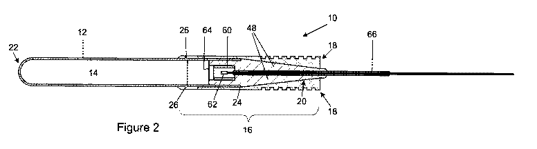
A cartridge (10) is shown in Figures 1 and 2 and includes a cylindrical
receptacle, in this embodiment a tube (12), filled with a propellant (14). A
stemming device (16) having a static member (18) and a piston (20) movable
relative to the static member is secured to the tube (12). In this embodiment
the static member (18) is provided by a split expansion sleeve and the piston
(20) has a cone at one end. The tube (12) and stemming device (16) together
define a substantially closed container.
CA 02869590 2014-10-03
WO 2013/150462
PCT/1B2013/052659
11
The tube (12) has a domed closed end (22) and is open at the other end
(24). At a zone approximately one quarter of the length of the tube (12) from
the open end there is a circumferentially extending rib (26) which is bounded
by an inclined surface (28) (Figure 3 and 4) and a radial surface (30).
The sleeve (18) has a securing end (32) and a free end (34) and has
longitudinally extending slits at both ends. More specifically there are four
slits (36) in the securing end (32) and three slits (38) which extend
approximately half way along the sleeve (18) in the free end (34). The slits
(36, 38) in both ends are equally spaced around the sleeve. Of course any
suitable number of slits can be provided. For example, there can be a single
slit at the securing end and two slits or more than three slits at the free
end.
Adjacent its securing end (32) the sleeve (18) has an internal groove (40) the
shape of which matches that of the rib (26). The section of the sleeve (18)
adjacent the free end (34) is formed with circumferentially extending, axially
spaced ribs (42) between which there are grooves (44). Internally the sleeve
(18) has a bore (46) which is cylindrical in shape over a portion of its
length
and tapering in shape over the remainder. The bore (46) decreases in cross-
sectional area in the direction away from its cylindrical part from the
securing
end to the free end. The slits (38) extend the full length of the tapering
bore
of the sleeve and part way along the length of the sleeve which has the
cylindrical bore.
The piston (20), in this embodiment, is formed by two parts (48). Turning now
to Figures 8, 9 and 10, the part (48) illustrated constitutes one half of the
piston (20). The part (48) has a flat surface (50) from which two pins (52)
protrude and in which there are two sockets (54). A groove (56) extends
along the centre line of the surface (50). At the larger end the groove (56)
enters a central recess (58) in the surface (50).
CA 02869590 2014-10-03
WO 2013/150462
PCT/1B2013/052659
12
The cartridge is assembled by placing the tube (12) in a jig in an upright
position. The propellant (14) is then poured into the tube (12) and tamped
down.
A small quantity of material which produces a flame when ignited, for
example black powder, is then placed in the cavity or socket formed by the
adjacent recesses (58) of the parts (48) of the piston (20) which are placed
face-to-face with the pins (52) in the sockets (54). The longitudinal axis of
the
cone is in the plane of the flat faces of the parts (48) that are in contact.
The
material can be in particulate form or moulded into the form of a sleeve as
shown at (60) in Figure 2.
An igniter (62) is also placed in the socket. A foil cover (64) is adhered to
the
piston (20) to close the cavity. An operating cord, in this embodiment a fuse
wire (66), attached to the igniter runs along the bore formed by the
registering grooves (56). A thin layer of adhesive can be applied to the
surfaces (50) if desired before they are pressed together.
The outer surface of one end of the piston is cylindrical and is stepped so as
to form a spigot which slides into the tube (12) when the piston is pressed
down onto the open end of the tube (12). A shoulder at the end of the spigot
limits the depth of penetration of the piston into the tube (12). The opposite
end is conical and forms a complementary fit within the tapering portion of
the sleeve (18).
The free end of the fuse wire (66) is threaded through the sleeve (18) (from
left to right as viewed in the drawings) and the piston (20) inserted into the
tube (12) until it is in the position shown in Figure 2.
The securing end (32) of the sleeve (18) is then pushed over the open end
(24) of the tube (12) until the rib (26) snaps into the groove (40) which
locks
the tube (12) to the sleeve (18).
CA 02869590 2014-10-03
WO 2013/150462
PCT/1B2013/052659
13
The cartridge (10) is now fully assembled and ready for use by pushing it,
domed end (22) leading, into a drilled borehole in the rock. If the borehole
is
horizontal then, using a stick of suitable length, the cartridge is pushed as
far
along the borehole as is required. If the borehole is vertical the cartridge
is
just dropped in.
When the igniter (62) is operated, the material in the socket or chamber
ignites, producing a flame and bursting the foil (64) so that a flame reaches
the propellant (14). Ignition of the material in the socket raises the
pressure
sufficiently to exert some force on the piston (20) to start the stemming
procedure. When the propellant (14) ignites, gas is generated which also
forces the piston (20) to move relative to the sleeve (18). Movement of the
piston (20) within the sleeve (18) causes radial expansion of the sleeve (18)
forcing the ribs (42) outwardly into contact with the surface of the borehole.
Whilst there is some gas leakage through the slits (38), it is insignificant
and
the bulk of gas generated is retained in the container provided by the tube
(12) and stemming device (16). This eventually causes the tube (12) to burst
releasing the gas into the borehole. The grip between the ribs (42) in the
expanded condition of the sleeve (18) and the rough surface of the drilled
borehole prevents the cartridge (10) from moving along the borehole and
traps the gas within the borehole causing the rock to fracture as a result of
the high pressure created by the gas.
The cartridge has been found to be highly effective in breaking rock without
the need for any additional stemming material. It thus completely eliminates
the need for the time-consuming and costly procedure of using stemming
material.
The stemming device (16) remains attached to the tube (12) during stemming
as the sliding fit between the sleeve and borehole prevents sufficient radial
expansion for the sleeve (18) to disengage from the rib (26). Also, the
CA 02869590 2014-10-03
WO 2013/150462
PCT/1B2013/052659
14
portion of the sleeve (18) which surrounds the end of the tube (12) provides
circumferential reinforcement which assists in preventing radial expansion of
the tube in that area and the consequent escape of gas between the piston
and tube. It is thus preferable that the sleeve extend over the tube to at
least
the depth of the piston in the tube, preferably further. Alternatively, some
form of circumferential reinforcement, such as a thickening of the sides wall
can be provided to assist in preventing radial expansion of the tube about the
piston.
The cylindrical end of the piston acts to keep the piston aligned within the
sleeve during its travel. This helps ensure proper expansion of the stemming
device and avoids potential misalignment which may occur with a purely
conical piston moving within a tapered bore. Misalignment can result in
incomplete stemming and also in gaps being formed between the piston and
sleeve which permit gas to escape therethrough. Both of these situations
would have an negative effect on the performance of the cartridge.
It will be appreciated that many embodiments of a cartridge exist which fall
within the scope of the invention, particularly regarding the configuration
and
operation of the stemming devices, the method by which it is secured to the
receptacle and the configuration of the receptacle.
For example, as shown in Figures 11 and 12, the piston (70) can be of one-
piece construction and have a cylindrical body (68) with a first end (71) and
a
second end (72). A nozzle (74) extends axially from the first end (71) and is
provided by a radially inwardly stepped projection. The second end (72) is
inwardly tapered from a radially outwardly stepped shoulder (76). A bore (78)
extends axially through the piston (70) and is radially enlarged adjacent the
first end (71) to form a chamber (80). Flame producing material, for example
black powder, is placed into the chamber (80) at the first end (71) of the
piston (70) as described above.
CA 02869590 2014-10-03
WO 2013/150462
PCT/1B2013/052659
This piston configuration has been found to be particularly effective. The
additional flame producing material produces a sustained, high temperature
flame. This permits a standard igniter to be used in the cartridge. Such
igniters have been found to produce erratic propellant ignition when used on
their own, particularly with relatively large propellant volumes. Furthermore,
although the precise mechanism is not fully understood, the nozzle appears
to assist in creating a flame jet which is highly effective in initiating and
maintaining propellant ignition.
Figure 13 illustrates a second embodiment of a cartridge according to the
invention. In this embodiment buttons (90) are provided on the surface of the
tube (12.1). Each button has an inclined camming surface and a locking
surface which intersects the camming surface. The sleeve (18.1) has
complementary holes (92) for receiving the buttons (90). As the end (94) of
the sleeve (18.1) is pressed onto the tube (12.1) it rides up over the camming
surfaces until the holes (92) are reached. With the holes (92) properly
aligned, the buttons (90) snap into the holes (92). The locking surfaces of
the
buttons (90) engage the peripheries of the respective holes (92) to prevent
the sleeve (18.1) from being pulled back off the tube (12.1).
Alternatively, as shown in Figures 14 and 15, the sleeve (18.2) can have
holes (92.2) for receiving buttons (90.2) with corresponding slits (96)
extending from the end (98) of the sleeve (18.2) centrally into each
hole (92.2). With the piston (70) in position in the open end (24.2) of
the tube (12.2), the end (98) of the sleeve (18.2) is forced over the
closed, rounded end (22.2) of the tube (12.2) until the buttons (90.2)
locate within the respective holes (92.2). No further movement of the
sleeve in the direction of the open end of the tube is permitted by this
arrangement.
CA 02869590 2014-10-03
WO 2013/150462
PCT/1B2013/052659
16
This configuration has been found to work particularly well as it
facilitates assembly of the cartridge and eliminates the potential of the
sleeve being separated from the tube during expansion of the
stemming device.
Figures 16 to 20 illustrate a cartridge according to a further embodiment of
the invention. In this embodiment a screw thread (100) at the open end of the
tube (12.3) cooperates with a complementary thread (102) provided internally
of the sleeve (18.3) to secure the sleeve to the tube.
The sleeve (18.3) has three elongate, longitudinally extending,
circumferentially spaced ports (104) at its free end (106) and an anchor
member (108) is associated with each port (104). Each anchor member (108)
has a lug (110) which extends centrally from one side of a panel (112). On
the opposite side, the panels each having axially spaced ribs (42.2) between
which there are grooves (44.2). Each lug (110) provides a complementary,
sliding fit within a port (104) with each panel (112) providing a
complementary fit over part of the outer surface of the sleeve (18.3).
The free end (114) of each lug (110) abuts the piston (70.2) and has a taper
complementary thereto. When the cartridge is ignited, the piston (70.2)
moves towards the sleeve (18.3), causing the tapered end of the piston
(70.2) to engage the lugs (110) of the anchor members (108). This displaces
the anchor members (108) outwardly from the sleeve (18.3) resulting in radial
expansion of the stemming device.
It will be appreciated that the stemming device may be varied in design to
allow for the radial expansion and engagement with the walls of the borehole.
For example, the sleeve (18) need not have slits to permit expansion, but
could have lines of weakness or any other suitable configuration. In
particular, it is not required that both the static member (18) and piston
(20,
CA 02869590 2014-10-03
WO 2013/150462
PCT/1B2013/052659
17
70) have tapered or inclined bearing surfaces. It is simply required that
radial
expansion occurs upon relative movement of the piston (20, 70) and static
member (18).
For example, as shown in Figure 21, the piston (120) could have a radiused
bearing surface (122) which moves within the tapered cavity (124) of the
sleeve (126) to cause radial expansion of the sleeve (126).
Referring to Figure 22, the piston (130) can provide a sliding fit over the
end
of the tube (12) and within the static member (132) which is in turn secured
to
the tube (12).
As shown in Figure 23, the static member (140) could be secured to a post
(142) extending centrally within the tube (12) and integral therewith. The
static member (140), in this embodiment, has a bearing surface (144) which
tapers outwardly from the post (142) and cooperates with a complementary
bearing surface (146) on the piston (148), a cylindrical body which slides
within the tube (12) over the post (142). Ignition of the propellant causes
the
piston (148) to move against the static member (140) with a resultant radially
outward expansion of the piston (148).
It is also possible for rotational movement to be achieved and employed by
the stemming device. For example, as shown in Figure 24, the piston (200)
has one end (202) which is a sliding fit within the tube (12). The opposite
end
(204) has a smaller diameter which is tapered. Intermediate the ends (202,
204) the piston is radially thickened (206) and provided with a course screw
thread which cooperates with a complementary thread (208) provided
internally of the static member (210) which has a sleeve-like configuration
and fits over the tube (12) in a manner analogous to that described with
reference to Figures 1 and 2. The thread (208) runs from about the end of the
tube (12) to an inward thickening (212) which provides, at one end (214), a
bearing surface complementary to, and abutting, the end (204) of the piston
CA 02869590 2014-10-03
WO 2013/150462
PCT/1B2013/052659
18
(200). The opposite end (216) of the thickened portion (212) is similarly,
outwardly tapered from the centre. A shaft (218) extends centrally from the
end (204) of the piston (200), through a passage (220) in the thickened
portion (212). The end (222) of the shaft is screw threaded and has a
complementarily threaded nut (224) secured thereto. The nut (224) has a lug
(226) extending from one side which registers in a longitudinally extending
groove (not shown) in the end (228) of the static member (210) to prevent
rotation thereof. The internal end (230) of the nut (224) abuts the end (216)
of
the thickened portion (212) and is complementarily tapered to provide a
conical surface.
In use, gas produced by the propellant forces the piston (200) towards the
static member (210) causing it to rotate through engagement with the screw
thread. Rotation of the piston (200) also results in rotation of the shaft
(218)
which is threaded to cause the nut (224) to be drawn inwardly towards the
piston (200) and static member (210). This also applies an axial force to the
opposite end (216) of the thickened portion (212) which results in its
radially
outward displacement. The thickened portion (212) is thus subject to
compression between the piston (200) and nut (224) and undergoes rapid
and effective radial expansion. To effect radial expansion the thickened
portion may be segmented.
Clearly, other configurations exist which make use of a rotating piston. For
example, the piston could be made to rotate on a post extending from the
tube, similarly to that illustrated in Figure 23, and to drive into the static
member with a screwing action to cause radial expansion.
A very important benefit of the cartridge of the invention, in large part a
result
of the two-piece construction, is that it can be provided with a stemming
device (16) at opposite ends of a receptacle (300), as illustrated in Figure
25.
Of course the receptacle (300) would, in this embodiment, be tubular and
open at both ends. A removable membrane, or one that can easily be
CA 02869590 2014-10-03
WO 2013/150462
PCT/1B2013/052659
19
ruptured can be provide over one or both ends to retain the propellant in the
tube until the stemming devices have been fitted. Such a cartridge finds
application in relatively thin structures, such as walls, where the end of the
borehole may not provide sufficient resistance to the expanding gas of the
propellant for effective blasting to occur.
Any suitable stemming device, or combination of stemming devices, including
those described above, can be used in such a cartridge. An igniter can be
associated with each stemming device if desired, but only one igniter will
often be sufficient. In such cases, the stemming device which does not have
an igniter or operating cord associated with it will either have no passage or
socket for these or will have these plugged. Once again, the configuration of
the stemming device, that of a static member and piston, means that it is a
simple matter to provide different pistons with the same static member.
Clearly, expansion of the stemming device can be achieved in many other
ways and many other embodiments of a cartridge which fall within the scope
of the invention will be apparent to those skilled in the art.