Note: Descriptions are shown in the official language in which they were submitted.
WO 2013/155521
PCT/US2013/036596
FLOATING WIND TURBINE
PLATFORM AND METHOD OF ASSEMBLING
CROSS REFERENCE TO RELATED APPLICATIONS
[0001]
BACKGROUND
[0002] Various embodiments of a wind turbine platform are described
herein. In particular, the embodiments described herein relate to an improved
floating wind turbine platform for use in large bodies of water.
[0003] Wind turbines for converting wind energy to electrical power
are
known and provide an alternative energy source for power companies. On land,
large groups of wind turbines, often numbering in the hundreds of wind
turbines,
may be placed together in one geographic area. These large groups of wind
turbines can generate undesirably high levels of noise and may be viewed as
aesthetically unpleasing. An optimum flow of air may not be available to these
land-base wind turbines due to obstacles such as hills, woods, and buildings.
1
CA 2870349 2019-08-21
CA 02870349 2014-10-10
WO 2013/155521
PCMJS2013/036596
[0004] Groups of wind turbines may also be located offshore, but near the
coast at locations where water depths allow the wind turbines to be fixedly
attached to a foundation on the seabed. Over the ocean, the flow of air to the
wind
turbines is not likely to be disturbed by the presence of various obstacles
(i.e., as
hills, woods, and buildings) resulting in higher mean wind speeds and more
power. The foundations required to attach wind turbines to the seabed at these
near-coast locations are relatively expensive, and can only be accomplished at
relatively shallow depths, such as a depth of up to about 25 meters.
[0005] The U.S. National Renewable Energy Laboratory has determined
that winds off the U.S. Coastline over water having depths of 30 meters or
greater
have an energy capacity of about 3,200 TWh/yr. This is equivalent to about 90
percent of the total U.S. energy use of about 3,500 TWh/yr. The majority of
the
offshore wind resource resides between 37 and 93 kilometers offshore where the
water is over 60 meters deep. Fixed foundations for wind turbines in such deep
water are not likely economically feasible. This limitation has led to the
development of floating platforms for wind turbines. Known floating wind
turbine
platforms are formed from steel and are based on technology developed by the
offshore oil and gas industry. There remains a need in the art however, for
improved platforms for floating wind turbine applications.
SUMMARY OF THE INVENTION
[0006] The present application describes various embodiments of a floating
wind turbine platform.
[0007] According to this invention there is provided a semisubmersible
wind turbine platform capable of floating on a body of water and supporting a
wind turbine over a vertical center column, the wind turbine platform, the
platform
CA 02870349 2014-10-10
WO 2013/155521
PCT/US2013/036596
including a vertical center column, and three or more vertical outer columns
spaced radially from the center column. Each of the outer columns is connected
to
the center column with one or more of: (a) a bottom beam extending
substantially
horizontally between a lower portion of the outer column and a lower portion
of
the center column, and (b) a top beam extending substantially horizontally
between an upper portion of the outer column and an upper portion of the
center
column. The center column and outer columns are made of concrete and are
buoyant with sufficient buoyancy to help support a wind turbine tower. The
outer
columns are not connected to each other by structurally substantial perimeter
linkages.
[0008] According to this invention there is also provided a semisubmersible
wind turbine platform capable of floating on a body of water and supporting a
wind turbine, the wind turbine platform. The platform includes a vertical
center
column, and three or more vertical outer columns spaced radially from the
center
column. Each of the outer columns is connected to the center column with (a) a
bottom beam extending substantially horizontally between a lower portion of
the
outer column and a lower portion of the center column, (b) a top beam
extending
substantially horizontally between an upper portion of the outer column and an
upper portion of the center column, and (c) a strut extending between a lower
portion of the outer column and an upper portion of the center column. The
center
column and outer columns are made of concrete and are buoyant with sufficient
buoyancy to support a wind turbine tower. The outer columns are not connected
to each other by substantial structural perimeter linkages.
[0009] According to this invention there is also provided a method of
assembling a floating wind turbine platform. The method includes assembling at
least three platform wings onto two or more floatation devices on a body of
water,
3
CA 02870349 2014-10-10
WO 2013/155521
PCT/US2013/036596
the platform wings having a bottom beam and at least a base portion of an
outer or
center column, with each floatation device supporting one or more platform
wings.
The barges are brought together arranged about a bottom keystone. Each of the
platform wings is attached to the bottom keystone to form the lower portion of
a
foundation for a wind turbine platform, with the outer columns spaced radially
from the bottom keystone, and the outer columns equally circumferentially
spaced
about the bottom keystone. The floatation devices are removed from under the
platform wings such that the foundation floats in the body of water to form a
floating wind turbine platform, thereby allowing further construction of the
platform in the water.
[0010] According to this invention there is also provided a wind generation
apparatus including a floating wind turbine platform having a concrete central
column, with a top portion of the central column having upwardly oriented
anchor
bolts embedded in the concrete. A wind turbine tower is mounted onto the
platform, the wind turbine tower being made of a fiber-reinforced composite
material and having a bottom base plate, with the base plate being bolted to
the
concrete central column using the anchor bolts.
[0011] Various advantages of this invention will become apparent to those
skilled in the art from the following detailed description of the preferred
embodiment, when read in light of the accompanying drawings.
BRIEF DESCRIPTION OF THE DRAWINGS
[0012] Fig. 1 is an elevational view of a spar buoy type floating wind
turbine
platform in accordance with this invention.
4
CA 02870349 2014-10-10
WO 2013/155521
PCT/US2013/036596
[0013] Fig. 1A is an enlarged view of a portion of an alternate embodiment
of
the floating wind turbine platform illustrated in Fig. 1, showing a vertical-
axis
wind turbine.
[0014] Fig. 2 is an enlarged view, partially in section, of the floating
wind
turbine platform illustrated in Fig. 1 partially spaced apart and showing one
embodiment of a connection joint between the tower and the hull.
[0015] Fig. 3A is an elevational view in cross section of a portion of a
first
alternate embodiment of the connection joint in accordance with this
invention.
[0016] Fig. 3B is an elevational view in cross section of a portion of a
second
alternate embodiment of the connection joint in accordance with this
invention.
[0017] Fig. 3C is an elevational view in cross section of a portion of a
third
alternate embodiment of the connection joint in accordance with this
invention.
[0018] Fig. 3D is an elevational view in cross section of a portion of a
fourth
alternate embodiment of the connection joint in accordance with this
invention.
[0019] Fig. 3E is an elevational view in cross section of a portion of a
fifth
alternate embodiment of the connection joint in accordance with this
invention.
[0020] Fig. 3F is an elevational view in cross section of a portion of a
sixth
alternate embodiment of the connection joint in accordance with this
invention.
[0021] Fig. 3G is an elevational view in cross section of a portion of a
seventh
alternate embodiment of the connection joint in accordance with this
invention.
[0022] Fig. 3H is an elevational view in cross section of a portion of an
eighth
alternate embodiment of the connection joint in accordance with this
invention.
[0023] Fig. 31 is an elevational view in cross section of a portion of a
ninth
alternate embodiment of the connection joint in accordance with this
invention.
[0024] Fig. 3J is an elevational view in cross section of a portion of a
tenth
alternate embodiment of the connection joint in accordance with this
invention.
CA 02870349 2014-10-10
WO 2013/155521
PCT/US2013/036596
[0025] Fig. 3K is an elevational view in cross section of a portion of an
eleventh alternate embodiment of the connection joint in accordance with this
invention.
[0026] Fig. 3L is an elevational view in cross section of a portion of a
twelfth
alternate embodiment of the connection joint in accordance with this
invention.
[0027] Fig. 4 is an elevational view in cross section of a portion of a
thirteenth
alternate embodiment of the connection joint in accordance with this
invention.
[0028] Fig. 5 is a perspective view of an alternate embodiment of the tower
illustrated in Fig. 1.
[0029] Fig. 6 is an elevational view of a first alternate embodiment of the
hull
illustrated in Fig. 1.
[0030] Fig. 6A is an enlarged elevational view in cross section of the
connection joint illustrated in Fig. 6.
[0031] Fig. 6B is an enlarged elevational view in cross section of an
alternate
embodiment of the first end of the hull illustrated in Fig. 6.
[0032] Fig. 7 is a perspective view of a second alternate embodiment of the
hull
illustrated in Fig. 1.
[0033] Fig. 8 is an elevational view of a second embodiment of a floating
composite wind turbine platform in accordance with this invention.
[0034] Fig. 9 is a top plan view of the hull platform illustrated in Fig.
8.
[0035] Fig. 10 is an elevational view of a second embodiment of the
floating
composite wind turbine platform illustrated in Fig. 8, showing an alternate
embodiment of the hull platform.
[0036] Fig. 11 is an elevational view of a third embodiment of a floating
composite wind turbine platform in accordance with this invention.
6
CA 02870349 2014-10-10
WO 2013/155521
PCT/US2013/036596
[0037] Fig. 12 is an elevational view of a fourth embodiment of a floating
composite wind turbine platform in accordance with this invention.
[0038] Fig. 13 is an elevational view of a fifth embodiment of a floating
composite wind turbine platform in accordance with this invention.
[0039] Fig. 14 is an elevational view of a sixth embodiment of a floating
composite wind turbine platform, showing a pontoon platform in accordance with
this invention.
[0040] Fig. 15 is an elevational view of the pontoon platform illustrated
in Fig.
14, showing a rotating turret.
[0041] Fig. 16 is a top plan view of a second embodiment of the pontoon
platform illustrated in Fig. 14.
[0042] Fig. 17 is a perspective view of a third embodiment of the pontoon
platform illustrated in Fig. 14.
[0043] Fig. 18A is a top plan view in cross section of a portion of a first
embodiment of a joint between the pontoon and the structural member of the
pontoon platform illustrated in Fig. 17.
[0044] Fig. 18B is a top plan view in cross section of a portion of a
second
embodiment of the joint between the pontoon and the structural member of the
pontoon platform illustrated in Fig. 17.
[0045] Fig. 19 is an elevational view of an alternate embodiment of the
floating
wind turbine platform illustrated in Fig. 1.
[0046] Fig 20 is an elevational view in cross section of a portion of an
alternate
embodiment of the tower illustrated in Fig. 1.
[0047] Fig. 21 is a perspective view of a fourth embodiment of the pontoon
platform illustrated in Fig. 14.
7
CA 02870349 2014-10-10
WO 2013/155521
PCT/US2013/036596
[0048] Fig. 22 is a perspective view of a seventh embodiment of a floating
wind turbine platform assembled and deployed according to the method of the
invention.
[0049] Fig. 23A is a plan view of a wing member on a barge.
[0050] Fig. 23B is a side elevational view of the wing member on a barge
shown in Fig. 23A.
[0051] Fig. 24A is a first plan view of a second step of the first phase of
the
method of assembling and deploying the floating wind turbine platform
illustrated
in Fig. 1.
[0052] Fig. 24B is a plan view of the second step of the first phase of the
method of assembling second and deploying the floating wind turbine platform
illustrated in Fig. 1, showing construction of the center piece on falsework.
[0053] Fig. 24C is a third plan view of the second step of the first phase
of the
method of assembling and deploying the floating wind turbine platform
illustrated
in Fig. 1, showing the center piece with the falsework removed.
[0054] Fig. 25 is a side elevational view of the portion of the floating
wind
turbine platform illustrated in Figs. 24A, 24B, and 24C, showing the barges
being
removed.
[0055] Fig. 26A is a plan view of a first step of the second phase of the
method
of assembling and deploying the floating wind turbine platform illustrated in
Fig.
1, showing the floating foundation near a dock.
[0056] Fig. 26B is a first side elevational view of the first step of the
second
phase of the method of assembling and deploying the floating wind turbine
platform illustrated in Fig. 26A, showing the columns being formed.
[0057] Fig. 26C is a second side elevational view of the first step of the
second
phase of the method of assembling and deploying the floating wind turbine
8
CA 02870349 2014-10-10
WO 2013/155521
PCT[US2013/036596
platform illustrated in Figs. 26A and 26B, showing the columns and struts
being
formed.
[0058] Fig. 27A is a first side elevational view of the second step of the
second
phase of the method of assembling and deploying the floating wind turbine
platform illustrated in Figs. 26A, 26B, and 26C, showing the center column
completed.
[0059] Fig. 27B is a second side elevational view of the second step of the
second phase of the method of assembling and deploying the floating wind
turbine
platform illustrated in Figs. 26A, 26B, and 26C, showing the struts being
completed.
[0060] Fig. 28A is a first side elevational view of the third step of the
second
phase of the method of assembling and deploying the floating wind turbine
platform illustrated in Figs. 26A through 27B, showing the outer columns being
completed.
[0061] Fig. 28B is a second side elevational view of the third step of the
second
phase of the method of assembling and deploying the floating wind turbine
platform illustrated in Figs. 26A through 27B, showing the outer columns
completed.
[0062] Fig. 29 is a side elevational view of the fourth step of the second
phase
of the method of assembling and deploying the floating wind turbine platform
illustrated in Figs. 26A through 28B, showing the top beams being completed.
[0063] Fig. 30 is a perspective view of a first step of a second embodiment
of
the method of assembling and deploying the floating wind turbine platform
according to the method of the invention.
9
CA 02870349 2014-10-10
WO 2013/155521
PCT/US2013/036596
[0064] Figs. 31 though 39 are perspective views of subsequent steps of the
second embodiment of the method of assembling and deploying the floating wind
turbine platform.
[0065] Fig. 40 is a perspective view of a final step of the second
embodiment of
the method of assembling and deploying the floating wind turbine platform.
[0066] Fig. 41 is a plan view of three wing members supported by two
barges.
[0067] Fig. 42 is an elevational view in cross-section illustrating
structural
aspects of elements of the platform.
[0068] Fig. 43 in a plan view of a completed wind generating device.
[0069] Fig. 44 is a perspective view of a bottom keystone.
[0070] Fig. 45 is a cross-sectional plan view of the lower portion of a
foundation having four wings.
DETAILED DESCRIPTION
[0071] The present invention will now be described with occasional
reference to the illustrated embodiments of the invention. This invention may,
however, be embodied in different forms and should not be construed as limited
to
the embodiments set forth herein, nor in any order of preference. Rather,
these
embodiments are provided so that this disclosure will be more thorough, and
will
convey the scope of the invention to those skilled in the art.
[0072] Unless otherwise defined, all technical and scientific terms used
herein have the same meaning as commonly understood by one of ordinary skill
in
the art to which this invention belongs. The terminology used in the
description of
the invention herein is for describing particular embodiments only and is not
intended to be limiting of the invention. As used in the description of the
invention
CA 02870349 2014-10-10
WO 2013/155521
PCT/US2013/036596
and the appended claims, the singular forms "a," "an," and "the" are intended
to
include the plural forms as well, unless the context clearly indicates
otherwise.
[0073] Unless otherwise indicated, all numbers expressing quantities of
ingredients, properties such as molecular weight, reaction conditions, and so
forth
as used in the specification and claims are to be understood as being modified
in
all instances by the term "about." Accordingly, unless otherwise indicated,
the
numerical properties set forth in the specification and claims are
approximations
that may vary depending on the desired properties sought to be obtained in
embodiments of the present invention. Notwithstanding that the numerical
ranges
and parameters setting forth the broad scope of the invention are
approximations,
the numerical values set forth in the specific examples are reported as
precisely as
possible. Any numerical values, however, inherently contain certain errors
necessarily resulting from error found in their respective measurements.
[0074] The embodiments of the invention disclosed below generally
provide improvements to various types of floating wind turbine platforms, such
as
spar buoy type platforms, tension leg type platforms, and semi-submersible
type
platforms. The invention includes improvements to various types of floating
wind
turbine platforms, including constructing components of the floating wind
turbine
platforms with materials selected to reduce the overall cost of the floating
wind
turbine platforms.
[0075] Referring to the drawings, particularly to Fig. 1, a first
embodiment
of a floating composite wind turbine platform 10 is shown anchored to the
seabed
S. The illustrated floating wind turbine platform 10 is a ballast stabilized,
spar
buoy type platform and includes a tower 12 attached to a hull 14 at a
connection
joint 16. Mooring lines 18 are attached to the hull 14 and further anchored to
the
seabed S by anchors 19. A wind turbine 20 is mounted to the tower 12.
11
CA 02870349 2014-10-10
WO 2013/155521
PCT/US2013/036596
[0076] A spar buoy type platform maintains its stability afloat by keeping
its center of gravity below its center of buoyancy. This relationship of the
center of
gravity being below the center of buoyancy may be achieved by filling a heavy
long tube or hull with ballast comprising water and dense material such as
rocks.
[0077] In the embodiments illustrated herein, the wind turbine 20 is a
horizontal-axis wind turbine. Alternatively, the wind turbine may be a
vertical-axis
wind turbine, such as shown at 20' in Fig. 1A. The size of the turbine 20 will
vary
based on the wind conditions at the location where the floating wind turbine
platform 10 is anchored and the desired power output. For example, the turbine
20
may have an output of about 5 MW. Alternatively, the turbine 20 may have an
output within the range of from about 1MW to about 10 MW.
[0078] The wind turbine 20 includes a rotatable hub 22. At least one rotor
blade 24 is coupled to and extends outward from the hub 22. The hub 22 is
rotatably coupled to an electric generator (not shown). The electric generator
may
be coupled via a transformer (not shown) and an underwater power cable 26 to a
power grid (not shown). In the illustrated embodiment, the rotor has three
rotor
blades 24. In other embodiments, the rotor may have more or less than three
rotor
blades 24.
[0079] In the illustrated embodiment, the tower 12 is formed as a tube and
is fabricated from fiber reinforced polymer (FRP) composite material. Non-
limiting examples of other suitable composite material include glass and
carbon
FRP. The tower may also be formed from a composite laminate material as shown
at 312 in Fig. 20. The illustrated tower 312 includes a first FRP composite
layer
314, a second FRP composite layer 316, and a foam core 318. Alternatively, the
tower 12 may be formed from concrete or steel in the same manner as the hull
14,
described in detail below. Additionally, the tower 12 may be formed from
steel.
CA 02870349 2014-10-10
WO 2013/155521
PCT/US2013/036596
[0080] The interior of the tower 12 defines a cavity 13 between a first end
12A (lower end when viewing Fig. 1) and a second end 12B (upper end when
viewing Fig. 1). As best shown in Fig. 2, a radially outwardly extending
flange
12F is formed at the first end 12A of the tower 12, as best shown in Fig. 1A.
The
radially extending flange 12F defines a portion of the connection joint 16.
[0081] The cavity 13 of the tower 12 may be filled with foam or concrete
for added rigidity. In the illustrated embodiment, foam F is shown filling a
portion
of the cavity 13 of the tower 12. Alternatively, the foam F, or concrete (not
shown), may fill the entire cavity 13 of the tower 12 from the first end 12A
to the
second end 12B. One non-limiting example of a suitable foam includes
polyurethane. Sufficiently rigid material other than foam and concrete may
also be
used to fill or partially fill the cavity 13 of the tower 12.
[0082] Advantageously, the tower 12 formed from composite material as
described above will have reduced mass above a waterline WL relative to a
conventional steel tower. Because the FRP composite tower 12 has reduced mass,
the mass of the hull 14 (e.g. self-weight and ballast, described in detail
below)
required below the water line WL to maintain stability of the floating wind
turbine
platform 10 may also be reduced. This will reduce the overall cost of the wind
generating device. As used herein, waterline is defined as the approximate
line
where the floating wind turbine platform 10 meets the surface of the water.
[0083] The tower 12 may have any suitable outside diameter and height. In
the illustrated embodiment, the outside diameter of the tower 12 tapers from a
diameter of about 6 meters at the first end 12A to a diameter of about 4
meters at
the second end 12B. Alternatively, the outside diameter of the tower 12 may be
any other desired diameter, such as within the range of from about 3 meters to
about 12 meters. In the illustrated embodiment, the height of the tower 12 is
about
13
CA 02870349 2014-10-10
WO 2013/155521
PCT/US2013/036596
90 meters. Alternatively, the height of the tower 12 may be within the range
of
from about 50 meters to about 140 meters.
[0084] In the illustrated embodiment, the hull 14 is formed as a tube and
is
fabricated from reinforced concrete. The interior of the hull 14 defines a
cavity 15
between a first end 14A (lower end when viewing Fig. 1) and a second end 14B
(upper end when viewing Fig. 1). Any desired process may be used to
manufacture the hull 14, such as a spun concrete process or conventional
concrete
forms. Alternatively, other processes such as those used in the precast
concrete
industry may also be used. The hull 14 may be reinforced with any desired
reinforcement member R. Non-limiting examples of suitable reinforcement
members R include high tensile steel cable and high tensile steel
reinforcement
bars or REBAR. Alternatively, the hull 14 may be formed from FRP composite in
the same manner as the tower 12, described above. Additionally, the hull 14
may
be formed from steel.
10085] The hull 14 may have any suitable outside diameter and height. In
the illustrated embodiment, the hull 14 has a first outside diameter D1 and a
second outside diameter D2 which is smaller that the first outside diameter
Dl.
The portion of the hull 14 having the first outside diameter D1 extends from
the
first end 14A to a tapered transition section 14T. The portion of the hull 14
having
the second outside diameter D2 extends from the transition section 14T to the
second end 14B. In the illustrated embodiment, the first outside diameter D1
is
about 8 meters and the second outside diameter D2 is about 6 meters.
Alternatively, the first and second outside diameters D1 and D2 of the hull 14
may
be any other desired diameters, such as within the range of from about 4
meters to
about 12 meters and within the range of from about 4.5 meters to about 13
meters,
respectively. Additionally, the hull 14 may have a uniform outside diameter.
In the
14
CA 02870349 2014-10-10
WO 2013/155521
PCT/US2013/036596
illustrated embodiment, the height of the hull 14 is about 120 meters.
Alternatively, the height of the hull 14 may be greater than or less than 120
meters, such as, for example, within the range of from about 50 meters to
about
150 meters.
[0086] A radially outwardly extending flange 14F is formed at the second
end 14B of the hull 14, as best shown in Fig. 2. The radially extending flange
14F
defines a portion of the connection joint 16. A first end 14A of the hull 14
is
closed by a plate 14P. The plate 14P may be formed from any suitable
substantially rigid material such as steel. Alternatively, the first end 14A
of the
hull 14 may be closed by a plate, which can be formed from any suitable
substantially rigid material such as steel.
[0087] In the illustrated embodiment, the connection joint 16 is formed by
connecting the flange 12F and the flange 14F. In the embodiment illustrated in
Fig. 2, the flanges 12F and 14F are connected by bolts 34 and nuts 36.
Alternatively, the flanges 12F and 14F may be connected by any other desired
fasteners, such as rivets, adhesives, or by welding.
[0088] It will be understood that the flange 12F of the tower 12 and the
flange 14F of the hull 14 may be formed as radially inwardly extending flanges
such that the fasteners (e.g. the bolts 34 and nuts 36) are installed within
the tower
and hull cavities, 13 and 15 respectively.
[0089] As shown in Fig. 2, the cavity 15 of the hull 14 may be filled with
ballast B to stabilize the floating wind turbine platform 10. In the
illustrated
embodiment, this ballast B is shown filling a portion of the cavity 15 of the
hull
14, such as a lower 1/3 of the cavity 15. Alternatively, the ballast B may
fill any
other desired portion of the cavity 15 of the hull 14 from the first end 14A
to the
second end 14B. In the illustrated embodiment, the ballast B is shown as
rocks.
CA 02870349 2014-10-10
WO 2013/155521
PCT/US2013/036596
Other non-limiting examples of suitable ballast material include water, scrap
steel,
copper ore, and other dense ores. Other sufficiently dense material may also
be
used as ballast to fill or partially fill the cavity 15 of the hull 14.
[0090] The hull 14 may pre-cast at a location distant from the location
where the floating wind turbine platform 10 will be deployed. During
manufacture
of the hull 14, the reinforcement members R may be pre-tensioned.
Alternatively,
during manufacture of the hull 14, the reinforcement members R may be post-
tensioned. Advantageously, the reinforced concrete hull 14 described above is
relatively heavy and may require less ballast B than conventional steel hulls.
[0091] A first end (upper end when viewing Fig. 1) of each mooring line 18
is attached to the hull 14. A second end (lower end when viewing Fig. 1) of
each
mooring line 18 is attached or anchored to the seabed S by an anchor 19, such
as a
suction anchor. Alternatively, other types of anchors may be used, such as a
drag
anchor, gravity anchor, or drilled anchor. In the illustrated embodiment, the
mooring lines 18 are configured as catenary moorings. The mooring lines 18 may
be formed from any desired material. Non-limiting examples of suitable mooring
line material include steel rope or cable, steel chain segments, and synthetic
rope
such as nylon. It will be understood that when the mooring lines 18 are slack
as
shown, the catenary curve formed by the mooring lines presents a lower angle
of
pull on the anchor 19 than would be the case if mooring lines 18 were nearly
straight. This enhances the performance of the anchor 19.
[0092] Referring to Fig. 19, a second embodiment of a floating composite
wind turbine platform is shown at 10'. The illustrated floating wind turbine
platform 10' is substantially similar to the floating composite wind turbine
platform shown at 10, but the tower 12 and the hull 14 are formed as a one-
piece
tower/hull member 11. In this embodiment, the connection joint 16 is not
required.
16
CA 02870349 2014-10-10
WO 2013/155521
PCT/US2013/036596
The one-piece tower/hull member 11 may be formed from FRP composite in the
same manner as the tower 12, described in detail above. Alternatively, the one-
piece tower/hull member 11 may be formed from reinforced concrete in the same
manner as the hull 14, described in detail above.
[0093] The interior of the tower/hull member 11 defines an elongated
cavity
17 within the tower/hull member 11. In the illustrated embodiment, a wall 38
extends transversely within the cavity 17 and divides the cavity 17 into a
tower
cavity portion 13' and a hull cavity portion 15'. At least a portion of the
tower
cavity portion 13' may be filled with foam or concrete (not shown in Fig. 19)
for
added rigidity as described above. At least a portion of the hull cavity
portion 15'
may be filled with ballast (not shown in Fig. 19) to stabilize the floating
wind
turbine platform 10' as described above.
10094] Referring to Figs. 3A through 3L, alternate embodiments of the
connection joint are shown at 16A though 16H respectively. As shown in Fig.
3A,
a portion of a first alternate embodiment of the connection joint is shown at
16A.
In the illustrated embodiment, the tower 12-1 and the hull 14-1 are formed
from
FRP composite as described above. Other materials can be used. The connection
joint 16A includes a tower 12-1 and a hull 14-1. Each of a pair of collar
members
12-1C includes a cylindrical collar portion 110 and a flange portion 112. The
collar members 12-1C may be integrally formed with the FRP composite tower
12-1 and hull 14-1, respectively. In the embodiment illustrated in Fig. 3A,
the
flange portions 112 are connected by bolts 34 and nuts 36. Alternatively, the
flange portions 112 may be connected by any other desired fasteners, such as
rivets, or by welding.
[0095] As shown in Fig. 3B, a portion of a second alternate embodiment of
the connection joint is shown at 16B. In the illustrated embodiment, the tower
12-
17
CA 02870349 2014-10-10
WO 2013/155521
PCT/US2013/036596
2 and the hull 14-2 are formed from steel as described above. A radially
extending
flange 12-2F is formed at the first end 12-2A of the tower 12-2, and a
radially
extending flange 14-2F is formed at the second end 14-2B of the hull 14-2. The
radially extending flange 12F defines a portion of the connection joint 16. In
the
embodiment illustrated in Fig. 3B, the flanges 12-2F and 14-2F are connected
by
bolts 34 and nuts 36. Alternatively, the flanges 12-2F and 14-2F may be
connected
by any other desired fasteners or by welding.
[0096] As shown in Fig. 3C, a portion of a third alternate embodiment of
the connection joint is shown at 16C. In the illustrated embodiment, the
connection joint 16C is substantially identical to the connection joint 16B,
except
that the tower 12-3 and the hull 14-3 are formed from FRP composite. In the
embodiment illustrated in Fig. 3C, the flanges 12-3F and 14-3F are connected
by
bolts 34 and nuts 36. Alternatively, the flanges 12-3F and 14-3F may be
connected
by any other desired fasteners or by welding.
10097] As shown in Fig. 3D, a portion of a fourth alternate embodiment of
the connection joint is shown at 16D. In the illustrated embodiment, the tower
12-
4 and the hull 14-4 are formed from FRP composite as described above. Each of
a
pair of collar members 12-4C includes a cylindrical collar portion 114 and a
flange
portion 116. The collar portion 114 of each of the pair of collar members 12-
4C is
inserted into a notch formed in the first end 12-4A of the tower 12-4 and in
the
second end 14-4B of the hull 14-4, respectively. A layer of adhesive may be
applied between the collar members 12-4C and each of the tower 12-4 and the
hull
14-4. In the embodiment illustrated in Fig. 3D, the flange portions 116 are
connected by bolts 34 and nuts 36. Alternatively, the flange portions 116 may
be
connected by any other desired fasteners or by welding.
18
CA 02870349 2014-10-10
WO 2013/155521
PCT/US2013/036596
[0098] As shown in
Fig. 3E, a portion of a fifth alternate embodiment of the
connection joint is shown at 16E. In the illustrated embodiment, the tower 12-
5
and the hull 14-5 are formed from FRP composite as described above. Each of a
pair of the collar members 12-4C include the cylindrical collar portion 114
and the
flange portion 116. The collar portion 114 of each of the pair of collar
members
12-4C is inserted into a notch formed in the first end 12-5A of the tower 12-5
and
in the second end 14-5B of the hull 14-5, respectively. A layer of adhesive
may be
applied between the collar members 12-4C and each of the tower 12-5 and the
hull
14-5. In the embodiment illustrated in Fig. 3E, the flange portions 116 are
connected by bolts 34 and nuts 36. Alternatively, the flange portions 116 may
be
connected by any other desired fasteners or by welding.
[0099] As shown in
Fig. 3F, a portion of a sixth alternate embodiment of the
connection joint is shown at 16F. In the illustrated embodiment, the tower 12-
6
and the hull 14-6 are formed from FRP composite as described above. A notch 12-
6N is formed in the first end 12-6A of the tower 12-6 and a notch 14-6N is
formed
in the second end 14-6B of the hull 14-6. The notch 12-6N of the first end 12-
6A
of the tower 12-6 is inserted into the notch 14-6N of the second end 14-6B of
the
hull 14-6 to define a lap joint.
[00100] As shown in
Fig. 3G, a portion of a seventh alternate embodiment of
the connection joint is shown at 16G. In the illustrated embodiment, the
connection joint 16G is substantially identical to the connection joint 16F,
except
that a layer of adhesive is applied between the notches 12-7N and 14-7N.
[00101] As shown in
Fig. 3H, a portion of an eighth alternate embodiment of
the connection joint is shown at 16H. In the illustrated embodiment, the
connection joint 16G is substantially identical to the connection joint 16F,
except
19
CA 02870349 2014-10-10
WO 2013/155521
PCT/US2013/036596
that lap joint is reinforced by a bolt 34 which extends through the lap joint
and is
fastened by a nut 36.
[00102] As shown in
Fig. 31, a portion of a ninth alternate embodiment of the
connection joint is shown at 16A. In the illustrated embodiment, the tower 12-
9 is
formed from the composite laminate material as also shown in Fig. 20. The
illustrated tower 12-9 includes the first FRP composite layer 314, the second
FRP
composite layer 316, and the foam core 318. The hull is not shown in Fig. 31,
but
may be any of the embodiments of the hull described herein. A collar member 12-
9C includes parallel cylindrical collar portions 320 and a flange portion 324.
A
channel 322 is defined between the collar portions 320. The collar member 12-
9C
is configured to be connected to another collar, such as the collar 12-1C. A
layer
of adhesive may be applied between the collar portions 320 and the foam core
318, and between the collar portions 320 and the first and second FRP
composite
layers 314 and 316, respectively. In the embodiment illustrated in Fig. 31,
the
collar 12-9C and the collar 12-1C are connected by bolts 34 and nuts 36.
Alternatively, the flange portions 112 may be connected by any other desired
fasteners, such as rivets, or by welding.
[00103] As shown in
Fig. 3J, a portion of a tenth alternate embodiment of the
connection joint is shown at 16J. In the illustrated embodiment, the tower 12-
10 is
formed from FRP composite as described above. The hull 14-10 is formed from
reinforced concrete, as described above. A first end 12-10A of the tower 12-10
is
embedded in and bonded to the cured concrete of the second end 14-10B of the
hull 14-10.
[00104] As shown in
Fig. 3K, a portion of an eleventh alternate embodiment
of the connection joint is shown at 16K. In the illustrated embodiment, the
tower
12-11 and the hull 14-11 are formed from composite laminate material as also
CA 02870349 2014-10-10
WO 2013/155521
PCT/US2013/036596
shown in Figs. 20 31. The illustrated tower 12-11 includes a first FRP
composite
layer 330, a second FRP composite layer 332, and a foam core 334. The first
end
12-11A of the tower 12-11 and the second end 14-11B of the hull 14-11 are
closed
by a third FRP composite layer 336. A layer of adhesive may be applied between
the third FRP composite layers 336.
[00105] As shown in Fig. 3L, a portion of a twelfth alternate embodiment of
the connection joint is shown at 16L. In the illustrated embodiment, the tower
12-
12 is formed from FRP composite as described above. If desired, an annular
cavity
340 may be formed in the tower 12-12 and filled with foam 342. Alternatively,
the
tower 12-12 may be formed from the composite laminate material as also shown
in Fig. 20. A plurality of threaded fasteners 344 are attached within fastener
cavities 346 in the first end 12-12A of the tower. The threaded fasteners 344
may
be embedded in the FRP composite material of the first end 12-12A of the tower
12-12 during manufacture of the tower 12-12. If desired, reinforcing fibers
348
may be wrapped around the threaded fasteners 344 to strengthen the bond
between
the FRP composite and the threaded fasteners.
[00106] The hull 14-12 is formed from reinforced concrete, as described
above. An annular plate 350 is attached to the second end 14-12B of the hull
14-12
by a bolt 354. Alternatively, the annular plate 350 may be attached to the
second
end 14-12B of the hull 14-12 by a cable (not shown), or any other means. The
plate 350 includes a plurality of holes 352 through which the bolts 344
extend.
Nuts 36 are attached to the bolts 344. Alternatively, the hull may be any of
the hull
embodiments illustrated in Figs. 3A through 3E.
[00107] Referring now to Fig. 4, a thirteenth embodiment of the connection
joint is shown at 122. In the illustrated embodiment, the tower 124 is formed
from
FRP composite, and the hull 126 is formed from reinforced concrete, as
described
21
CA 02870349 2014-10-10
WO 2013/155521
PCT/US2013/036596
above. The tower 124 is substantially tubular and includes a cavity 125. The
hull
126 is also substantially tubular and includes an outer wall 126W at the
second
end 126B of the hull 126. The first end 124A of the tower 124 is inserted into
the
second end 126B of the hull 126. The concrete that forms the outer wall 126W
extends inwardly and upwardly into the cavity 125 of the tower 124 to define a
rigidity member 130. When cured, the rigidity member 130 provides added
rigidity to the tower 124.
[00108] The connection joint 122 may be formed by inserting the first end
124A of the tower 124 into a hull form (not shown) which defines the shape of
the
second end 126B of the hull 126 to be formed. Concrete may be poured (as
indicated by the arrows 128) through the cavity 125 of the tower 124 and into
the
hull form to form the outer wall 126W of the second end 126B of the hull 126.
When the concrete is cured, the concrete of the rigidity member 130 is
contiguous
with the concrete of the outer wall 126W of the second end 126B of the hull
126,
thus the first end 124A of the tower 124 is embedded in and bonded to the
second
end 126B of the hull 126. Additionally, an outside surface of the first end
124A
may be textured such that it interlocks and bonds with the concrete of the
outer
wall 126W of the second end 126B of the hull 126, in the region identified by
the
numeral 132 in Fig. 4.
[00109] Fig. 5 illustrates an alternate embodiment of the tower 212. The
illustrated tower 212 is formed from a plurality of rings or sections 216. The
tower
sections 216 are connected to each other at connection joints 218. The
connection
joints 218 may be any of the connection joints described and illustrated in
Figs. 2,
3A through 3L, and 4. As described above regarding the tower 12, the tower
sections may 216 may be fabricated from FRP composite material, reinforced
concrete, or steel. The tower 212 may also have any suitable outside diameter
and
22
CA 02870349 2014-10-10
WO 2013/155521
PCT/US2013/036596
height. The tower sections 216 may also be connected by a post-tensioning
cable
in the same manner as described below regarding the hull sections 220.
[00110] Fig. 6 illustrates a first alternate embodiment of the hull 214.
The
illustrated hull 214 is formed from a plurality of rings or sections 220. The
hull
sections 220 are connected to each other at connection joints 222. The
connection
joints 222 may be any of the connection joints described and illustrated in
Figs. 2,
3A through 3L, and 4. As described above regarding the hull 14, the hull
sections
216 may be fabricated from FRP composite material, reinforced concrete, or
steel.
The hull 214 may also have any suitable outside diameter and height.
Alternatively, as best shown in Fig. 6A, the hull sections 220 may be
connected by
a post-tensioning cable 225 running through some or all of the hull sections
220
thereby clamping the hull sections 220 together and defining the hull 214. A
sealing member, such as a gasket G, may be disposed between the hull sections
220 to seal the connection joints 222. Non-limiting examples of suitable
gasket
material include neoprene, caulking, rubber, and other elastomers.
[00111] Referring to Fig. 6B, a lower most hull section 221 at the first
end
214A of the hull 214 may be formed from concrete and have an outside diameter
significantly larger than an outside diameter of the sections 220. The hull
section
221 would thereby have a greater mass than a hull section 220, and provide
additional ballast to the hull 214.
[00112] Referring to Fig. 7, a second alternate embodiment of the hull is
illustrated at 28. The hull 28 includes a plurality of hollow tube members 30.
In
the illustrated embodiment, the tube members 30 are connected by elongated
webs
32. The tube members 30 may be fabricated from FRP composite material and
each tube member 30 may be filled or partially filled with foam F or concrete
for
added rigidity, as described above. Alternatively, the hollow tube members 30
23
CA 02870349 2014-10-10
WO 2013/155521
PCT/US2013/036596
may be formed from concrete in the same manner as the hull 14 described above.
In the illustrated embodiment, the hull 28 has six hollow tube members 30. In
other embodiments, the hull 28 may have more or less than six hollow tube
members 30.
[00113] Referring now to Fig. 8, a second embodiment of a floating
composite wind turbine platform 40 is shown anchored to the seabed S. The
illustrated floating wind turbine platform 40 is a mooring line stabilized,
tension
leg type platform and includes the tower 12 attached to a hull platform 44 at
a
connection joint 46. Mooring lines 48 are attached to the platform 44 and
further
anchored via anchors 19 to the seabed S. The wind turbine 20 is mounted to the
tower 42.
[00114] A tension leg type platform maintains its stability afloat through
a
buoyant hull or platform anchored to the seabed by taut mooring lines. This
type
of floating wind turbine platform may be substantially lighter than other
types of
floating wind turbine platforms because the center of gravity does not have to
be
below the center of buoyancy.
[00115] Referring to the embodiment illustrated in Figs. 8 and 9, the
platform
44 includes a central portion 50 and legs 52 extending radially outwardly of
the
central portion 50. A vertically extending portion 54 extends outwardly from
the
central portion 50 (upwardly when viewing Fig. 8). The interior of the
platform 44
defines a cavity substantially filled with air for buoyancy. In the
illustrated
embodiment, the platform 44 has three legs 52. In other embodiments, the
platform 44 may have more or less than three legs 52.
[00116] The platform 44 may be formed from reinforced concrete as
described above. Alternatively, the platform 44 may be formed from FRP
24
CA 02870349 2014-10-10
WO 2013/155521
PCT/US2013/036596
composite in the same manner as the tower 12, described above. Additionally,
the
platform 44 may be formed from steel.
[00117] The platform 44 may have any desired dimensions. In the illustrated
embodiment for example, each of the legs 52 of the platform 44 has a length of
about 45 meters when measured from a center C of the platform 44.
Alternatively,
each of the legs 52 may have a length within the range of from about 30 meters
to
about 100 meters when measured from the center C of the platform 44.
[00118] A radially extending flange 44F is formed at a first end of the
vertically extending portion 54 (upper end when viewing Fig. 8). The radially
extending flange 44F defines a portion of the connection joint 46.
[00119] In the illustrated embodiment, the connection joint 46 is formed by
connecting the flange 12F of the tower 12 and the flange 44F. The flanges 12F
and
44F may be connected by bolts 34 and nuts 36 as shown in Fig. 2 and described
above. Alternatively, the flanges 12F and 44F may be connected by any other
desired fasteners, such as rivets, adhesive, or by welding. Additionally, the
connection joint 46 may be any of the connection joints described and
illustrated
in Figs. 2, 3A through 3L, and 4.
[00120] A first end (upper end when viewing Fig. 8) of each mooring line 48
is attached to a distal end of each leg 52 of the platform 44. A second end
(lower
end when viewing Fig. 8) of each mooring line 48 is attached or anchored to
the
seabed S by an anchor 19, as described above. In the illustrated embodiment,
the
mooring lines 48 are configured as taut moorings. The mooring lines 48 may be
formed from any desired material. Non-limiting examples of suitable mooring
line
material include steel rope or cable, steel chain segments, synthetic rope
such as
nylon rope, and composite tendons such as FRP tendons. As shown in Fig. 8, a
lower portion of the tower 12 (i.e., the first end 12A) is below the water
line WL.
CA 02870349 2014-10-10
WO 2013/155521
PCT/US2013/036596
[00121] Referring to Fig. 10, a second embodiment of the mooring line
stabilized, tension leg type platform is shown at 40'. The illustrated
floating wind
turbine platform 40' includes the tower 12' attached to a hull platform 44' at
a
connection joint 46'. Mooring lines 48 are attached to the hull platform 44
and
further anchored to the seabed (not shown in Fig. 10). The wind turbine 20 is
mounted to the tower 12'. The illustrated hull platform 44' is substantially
similar
to the hull platform 44, but the vertically extending portion 54' is longer
than the
vertically extending portion 54. In the illustrated embodiment, the vertically
extending portion 54' is configured such that a first end 54A', and its
attached
flange 44F is above the waterline WL. In the illustrated embodiment, the
vertically
extending portion 54' has a length of about 40 meters. Alternatively, the
vertically
extending portion 54' may have a length within the range of from about 5
meters
to about 50 meters.
[00122] Referring now to Fig. 11, a third embodiment of a floating
composite wind turbine platform 60 is shown anchored to the seabed S. The
illustrated floating wind turbine platform 60 is similar to the mooring line
stabilized, tension leg type platform 40 illustrated in Fig. 8 and includes a
tower 62
attached to the hull platform 44 at a connection joint 66. Mooring lines 48
are
attached to the hull platform 44 and further anchored via anchors 19 to the
seabed
S. The wind turbine 20 is mounted to the tower 62. Cable stays 64 are attached
to
the hull platform 44 and further attached to the tower 62.
[00123] In the illustrated embodiment, the tower 62 is formed as a tube and
is fabricated from fiber reinforced polymer (FRP) composite material. Non-
limiting examples of suitable FRP composite material include glass and carbon
FRP. Alternatively, the tower 62 may be formed from concrete or from steel, as
described above.
26
CA 02870349 2014-10-10
WO 2013/155521
PCT/US2013/036596
[00124] Because the cable stays 64 reduce bending stress in the tower 62,
the
tower 62 can be of a smaller diameter than the tower 12 illustrated in Fig. 8.
For
example, the tower 62 may have any suitable outside diameter and height. In
the
illustrated embodiment, the outside diameter of the tower 62 is about 4
meters.
Alternatively, the outside diameter of the tower 62 may be any other desired
diameter, such as within the range of from about 3 meters to about 10 meters.
In
the illustrated embodiment, the height of the tower 62 is about 90 meters.
Alternatively, the height of the tower 62 may be within the range of from
about 40
meters to about 150 meters.
[00125] The interior of the tower 62 also defines a cavity (not shown in
Fig.
11) between the first end 62A and the second end 62B. A radially extending
flange
62F is formed at the first end 62A of the tower 62, as best shown in Fig. 4.
The
radially extending flange 62F defines a portion of the connection joint 66.
[00126] In the illustrated embodiment, the connection joint 66 is formed by
connecting the flange 62F and the flange 44F. The flanges 62F and 44F may be
connected by bolts 34 and nuts 36 as shown in Fig. 2 and described above.
Alternatively, the flanges 62F and 44F may be connected by any other desired
fasteners, such as rivets, adhesive, grout, or by welding. Additionally, the
connection joint 66 may be any of the connection joints described and
illustrated
in Figs. 2, 3A through 3L, and 4.
[00127] A first end (lower end when viewing Fig. 11) of each cable stay 64
is
attached to a distal end of each leg 52 of the hull platform 44. A second end
(upper
end when viewing Fig. 11) of each cable stay 64 is attached to a mid-point 62M
of
the tower 62. The cable stays 64 support and reduce bending stress in the
tower
62. The cable stays 64 may be formed from any desired material. Non-limiting
examples of suitable mooring line material include steel rope or cable, steel
chain
27
CA 02870349 2014-10-10
WO 2013/155521
PCT/US2013/036596
segments, synthetic rope such as nylon rope, and composite tendons such as FRP
tendons.
[00128] Referring now to Fig. 12, a fourth embodiment of a floating
composite wind turbine platform 70 is shown anchored to the seabed S. The
illustrated floating wind turbine platform 70 is similar to the floating
composite
wind turbine platform 60 illustrated in Fig. 11 and includes the tower 62
attached
to the hull platform 44 at the connection joint 66. Mooring lines 74 are
attached to
the hull platform 44 and further anchored to the seabed S. The wind turbine 20
is
mounted to the tower 62. Cable stays 64 are attached to the hull platform 44
and
further attached to the tower 62.
[00129] In lieu of the taut mooring lines 48 shown in Fig. 11, the mooring
lines 74 are configured as catenary moorings, as described above. The floating
composite wind turbine platform 70 further includes a large mass 72 suspended
from the hull platform 44 by cables 76. The mass 72 may have any desired
weight,
such as a weight of about 1000 kg. Alternatively, the mass 72 may have a
weight
within the range of from about 10 kg to about 1500 kg. The mass 72 may be
formed form any material having the desired weight. Non-limiting examples of
material suitable for use as the mass 72 include one or more rocks, pieces of
concrete, and pieces of steel. These one or more items may be contained in a
net, a
bucket, or other outer shell or container.
[00130] A first end (lower end when viewing Fig. 12) of each cable 76 is
attached to the mass 72. A second end (upper end when viewing Fig. 12) of each
cable 76 is attached to a distal end of each leg 52 of the hull platform 44.
Non-
limiting examples of suitable cable material include steel rope or cable,
steel chain
segments, and synthetic rope such as nylon rope, and composite tendons such as
FRP tendons.
28
CA 02870349 2014-10-10
WO 2013/155521
PCT/US2013/036596
[00131] Referring now to Fig. 13, a fifth embodiment of a floating
composite
wind turbine platform 80 is shown anchored to the seabed S. The illustrated
floating wind turbine platform 80 is a mooring line stabilized, semi-
submersible
type platform and includes a tower 82 attached to a pontoon platform 84.
Mooring
lines 90 are attached to the pontoon platform 84 and further anchored via
anchors
19 to the seabed S. The wind turbine 20 is mounted to the tower 82. The tower
82
may be any suitable tower and may be identical to the tower 12 described
above.
Thus, the tower 82 may be formed from reinforced concrete, FRP composite, or
from steel as described above.
[00132] The pontoon platform 84 includes a plurality of buoyancy members
or pontoons 86 connected by structural members 88. In the illustrated
embodiment, the pontoon platform 84 has three pontoons 86. In other
embodiments, the pontoon platform 84 may have more or less than three pontoons
86. The illustrated pontoons 86 have a radially extending flange 87 formed at
a
first end 86A of each pontoon 86. Alternatively, the pontoons 86 may be formed
without the flanges 87.
[00133] In the embodiment of the pontoon platform 84 as shown in Fig. 13,
the tower 82 may be attached to one pontoon 86 via a connector joint (not
shown).
This connector joint may be any of the connection joints described and
illustrated
in Figs. 2, 3A through 3L, and 4. In a second embodiment of the pontoon
platform
84' as shown in Fig. 16, the pontoons 86 are connected to a central hub 92 by
structural members 94. In this embodiment, the tower 82 is attached to the
central
hub 92 via a connector joint (not shown), but such as any of the connection
joints
described and illustrated in Figs. 2, 3A through 3L, and 4.
[00134] In the illustrated embodiment, the pontoons 86 are substantially
hollow and define a cavity. A portion of the cavity of any of the pontoons 86
may
29
CA 02870349 2014-10-10
WO 2013/155521
PCT/US2013/036596
be filled with ballast B to help stabilize the floating wind turbine platform
80.
Alternatively, the ballast B may fill the entire cavity of any of the pontoons
86.
Non-limiting examples of suitable ballast material include water, rocks,
copper
ore, and other dense ores. Other sufficiently dense material may also be used
as
ballast to fill or partially fill the cavities of the pontoons 86.
[00135] The pontoons 86 may be formed from reinforced concrete, FRP
composite, or from steel as described above. The structural members 88 may
also
be formed from reinforced concrete, FRP composite, or from steel as described
above.
[00136] The pontoon platform 84 may have any desired dimensions. For
example, each of the pontoons 86 may have an outside diameter of about 12
meters and a height of about 30 meters. Alternatively, the pontoons 86 may
have
an outside diameter within the range of from about 10 to about 50 meters and a
height within the range of from about 10 meters to about 40 meters. A distance
D
measured between the centers of the pontoons 86 may be about 30 meters.
Alternatively, the distance D may be within the range of from about 15 meters
to
about 100 meters.
[00137] A first end (upper end when viewing Fig. 13) of each mooring line
90 is attached to one pontoon 86 of the pontoon platform 84. A second end
(lower
end when viewing Fig. 13) of each mooring line 90 is attached or anchored to
the
seabed S by the anchor 19, as described above. In the illustrated embodiment,
the
mooring lines 90 are configured as catenary moorings. The mooring lines 90 may
be formed from any desired material. Non-limiting examples of suitable mooring
line material include steel rope or cable, steel chain segments, and synthetic
rope
such as nylon rope, and composite tendons such as FRP tendons.
CA 02870349 2014-10-10
WO 2013/155521
PCT/US2013/036596
[00138] Referring now to Fig. 14, a sixth embodiment of a floating
composite wind turbine platform 100 is shown anchored to the seabed S. The
illustrated floating wind turbine platform 100 is substantially similar to the
floating composite wind turbine platform 80 illustrated in Fig. 13 and
includes a
tower 102 attached to the pontoon platform 84, as described above. Each
mooring
line 90 is attached to one pontoon 86 of the pontoon platform 84 and further
anchored to the seabed S via the anchor 19. The wind turbine 20 is mounted to
the
tower 102. A cable stay 104 is attached to each pontoon 86 of the pontoon
platform 84 and further attached to a first end 102A of the tower 102.
[00139] Because the cable stays 104 reduce bending stress in the tower 102,
the tower 102 can be of a smaller diameter than the tower 82 illustrated in
Fig. 13.
For example, the tower 102 may have any suitable outside diameter and height.
In
the illustrated embodiment, the outside diameter of the tower 102 is about 4
meters. Alternatively, the outside diameter of the tower 102 may be any other
desired diameter, such as within the range of from about 3 meters to about 12
meters. In the illustrated embodiment, the height of the tower 102 is about 90
meters. Alternatively, the height of the tower 102 may be within the range of
from
about 50 meters to about 140 meters.
[00140] Referring now to Fig. 15, the pontoon platform 84 may include a
rotating turret 106 mounted to a lower end of the pontoon platform 84. In the
embodiment illustrated in Fig. 15, the mooring lines 90 are attached to the
rotating
turret 106, rather than the pontoons 86. In this embodiment, the floating
composite
wind turbine platform, such as the platforms 80 and 100, may rotate relative
to the
turret 106 and thus self-align in response to the wind direction and ocean
currents.
[00141] Referring now to Figs. 17, 18A, and 18B, a third embodiment of the
pontoon platform is illustrated at 140. The pontoon platform 140 includes a
31
CA 02870349 2014-10-10
WO 2013/155521
PCT/US2013/036596
plurality of buoyancy members or pontoons 142 connected by structural members
144. In the illustrated embodiment, the pontoon platform 140 has three
pontoons
142. In other embodiments, the pontoon platform 140 may have more or less than
three pontoons 142. The illustrated pontoons 142 have a radially extending
flange
146 formed at a first end 142A of each pontoon 142. Alternatively, the
pontoons
142 may be formed without the flanges 146.
[00142] In the illustrated embodiment, the pontoons 142 are substantially
hollow and define a cavity and are formed from reinforced concrete. The
illustrated structural members 144 are substantially tubular, define a cavity
145,
and are formed from FRP composite.
[00143] As best shown in Fig. 18A, in a first embodiment of the pontoon
platform 140, the pontoon 142 includes an outer wall 142W. First and second
ends
144A and 144B, respectively, of the structural members 144 are inserted into
the
outer walls 142W of the pontoons 142. The concrete that forms the outer wall
142W extends into the cavities 145 of each structural member 144 to define a
rigidity member 148. When cured, the rigidity member 148 provides added
rigidity to the pontoon platform 140.
[00144] A second embodiment of the pontoon platform is illustrated at 140'
in Fig. 18B. The pontoon platform 140' is substantially identical to the
pontoon
platform 140, but does not include the rigidity member 148. The first and
second
ends 144A and 144B, respectively, of the structural members 144 are inserted
into
and bonded to the outer walls 142W of the pontoons 142.
1001451 The rigidity member 148 may be formed by inserting the first and
second ends 144A and 144B, respectively, of the structural members 144 into a
pontoon form (not shown) which defines the shape of the pontoon to be formed.
Concrete may be poured into the pontoon form to define the outer wall 142W of
32
CA 02870349 2014-10-10
WO 2013/155521
PCT/US2013/036596
the pontoon 142. This concrete will also flow into the cavity 145 of the
structural
member 144. When the concrete is cured, the concrete of the rigidity member
148
is contiguous with the concrete of the outer wall 142W of the pontoon 142,
thus
the first and second ends 144A and 144B of the structural members 144 are
respectively embedded in and bonded to the pontoons 142. Additionally, an
outside surface of each of the first and second ends 144A and 144B,
respectively,
of the structural members 144 may be textured such that each outside surface
interlocks and bonds with the concrete of the outer walls 142W of the pontoons
142.
[00146] It will be understood that the structural members 144 may also be
formed from reinforced concrete or from steel as described above.
[00147] In the embodiment of the pontoon platform 140 as shown in Fig. 17,
a tower, such as the tower 82 (illustrated by a phantom line in Fig. 17) may
be
attached to one of the pontoons 142 via a connector joint (not shown). This
connector joint may be any of the connection joints described and illustrated
in
Figs. 2, 3A through 3L, and 4.
[00148] Referring now to Fig. 21, a fourth embodiment of the pontoon
platform is illustrated at 440. The pontoon platform 440 includes a plurality
of
buoyancy members or pontoons 442 connected to a central pontoon 444 by
structural members 446. In the illustrated embodiment, the pontoon platform
440
has three pontoons 442. In other embodiments, the pontoon platform 440 may
have more or less than three pontoons 442. The illustrated pontoons 442 have a
radially extending flange 448 formed at a first end 442A of each pontoon 442.
Alternatively, the pontoons 442 may be formed without the flanges 448. In this
embodiment, a tower, such as the tower 82, is attached to the central pontoon
444
via a connector joint (not shown), but such as any of the connection joints
33
CA 02870349 2014-10-10
WO 2013/155521
PCT/US2013/036596
described and illustrated in Figs. 2, 3A through 3L, and 4. Alternatively, the
tower
82 may be attached to any of the three pontoons 442.
[00149] Each of the illustrated pontoons 442 is formed from a plurality of
rings or sections 450. The sections 450 are connected to each other at
connection
joints 452. As described above regarding the hull 14, the sections 450 may be
fabricated from FRP composite material, reinforced concrete, or steel. The
sections 450 may be connected by post-tensioning cables 454 running through
some or all of the sections 450 thereby clamping the sections 450 together and
defining the pontoon 442. A sealing member, such as the gasket G, may be
disposed between the sections 450 to seal the connection joints 452.
Alternatively,
the connection joints 452 may be any of the connection joints described and
illustrated in Figs. 2, 3A through 3L, and 4.
[00150] Attachment rings 456 are circumferentially mounted to an outside
surface of the pontoons 442 and provide a mounting structure for attaching the
structural members 446 to the pontoons 442. The attachment rings 456 may be
formed from steel, FRP composite material, or reinforced concrete.
Alternatively,
the attachment rings 456 may be mounted in the connection joint 452 between
two
adjacent sections 450.
[00151] Once the sections 450 are assembled to form the pontoon 442, a
closing member 458 may be attached to the second end 442B of the pontoon 442.
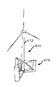
[00152] Referring to Fig. 22, there is illustrated at 510 a seventh
embodiment
of a floating wind turbine platform. The floating wind turbine platform 510
includes a foundation 514 that supports a composite tower 512. The composite
tower 512 supports a wind turbine 516. The illustrated composite tower 512 is
made of light-weight, corrosion resistant material, such as a fiber reinforced
polymer such as E-glass and a polyester polymer resin. The composite tower 512
34
CA 02870349 2014-10-10
WO 2013/155521
PCT/US2013/036596
may be made of other desired materials that provide support for the wind
turbine
516. The composite tower 512 walls may be a solid structure, or may be a cored
structure. For example. the composite tower 512 may be any of the towers
described above, including for example the towers 12, 12', 212, and 312. The
foundation 514 is structured and configured to float, semi-submerged, in a
body of
water. Mooring lines 518 may be attached to the wind turbine platform 510 and
further attached to anchors, such as the anchors 19 shown above, in the seabed
to
limit to movement of the wind turbine platform 510 on the body of water. It
will
be understood that the illustrated mooring lines 518 may be slack, i.e.,
catenary
mooring lines, such as shown in Figs. 12 through 15, and do not have to be in
tension during normal operation of the wind turbine platform 510. The
foundation
is semisubmersible, and therefore a portion of the foundation 514 will be
above
water when the foundation is floating in the water. Further, the foundation
514
will float upright even with the bending load or moment applied to the
platform by
the wind stress exerted on the tower 512 and the wind turbine 516. This is in
contrast to a vertical tension system such as that shown in Fig. 10, wherein
if the
tension lines are cut, the platform will tip over.
[00153] The illustrated foundation 514 is formed from three bottom beams
521 that extend radially outwardly from an interior or center column 522. In
the
illustrated embodiment, the bottom beams 521 are positioned such that the
angle
between the centerlines of adjacent bottom beams 521 is approximately 120-
degrees. The illustrated bottom beams 521 are pre-stressed concrete members.
It
will be understood that the bottom beams 521 may be formed from other desired
materials. The benefit of using concrete is that it is lighter than other
materials,
such as steel, and is more resistant to corrosion than steel is. Three outer
columns
524 are mounted at or near the distal ends of the bottom beams 521. The outer
CA 02870349 2014-10-10
WO 2013/155521
PCT/US2013/036596
columns 524 are further optionally connected to the center column 522 by top
beams 526. Optional struts 528 extend between and connect the upper portion or
end of the center column 522 and the distal ends of the bottom beams 521 or
the
lower ends of the outer columns 524. The embodiment of the floating wind
turbine
platform 510 illustrated in Fig. 22 has a height of about 35 meters (115 ft).
The
embodiment of the tower 512 illustrated in Fig. 22 has height of about 85
meters
(279 ft). It will be understood that the floating wind turbine platform 510
and the
tower 512 may be manufactured at any desired height.
[00154] Each outer column 524 may be formed from a plurality of sections
524S, as shown in Figs. 22, 28A, and 28B. The center column 522 may also be
formed from a plurality of sections 522S, as also shown in Figs. 22, 28A, and
28B.
[00155] A first embodiment of the method of assembling and deploying the
floating wind turbine platform 510 is illustrated in Figs. 23A through 29. As
shown, the wind turbine platform 510 may be assembled in two phases.
[00156] In a first phase (phase I) of assembly, three wing members 530 may
be cast or placed on separate barges B. Each illustrated wing member 530
includes
a bottom beam 521 and a base portion 524P of an outer column 524. If desired,
the
cast wing members 530 may be post-tensioned with reinforcements, as
illustrated
with the dashed lines in Figs. 23A and 23B. A strut anchor 528A may be formed
between and attached to the bottom beam 521 and the base portion 524P. Each of
the illustrated barges B has a deck surface of about 150 ft x 60 ft, although
barges
having other suitable sizes of deck surfaces may be used. In the illustrated
embodiment, the base portion 524P has a height of about 32 ft, although the
base
portion 524P may have any other suitable height.
[00157] After the wing members 530 have been cast, the three barges B will
be moved to a relatively calm area, such as a harbor area. The three barges B
36
CA 02870349 2014-10-10
WO 2013/155521
PCT/US2013/036596
containing the three wing members 530 will be fastened together with an
attachment structure, such as a temporary frame 536 shown in Fig. 24A and 24B.
In the illustrated embodiment, the frame 536 is a substantially triangular
shaped
steel structure. Alternatively, the frame 536 may have other desired sizes and
shapes and may be formed from other material.
[00158] Optionally, falsework (not shown) may be used to support the frame
536 during construction. The bottom keystone 532 will then be constructed
within
or on the frame 536. The keystone 532 includes a center column support portion
522P upon which the center column 522 will be built, as described below. The
keystone 532 also includes circumferentially spaced connection faces 623
oriented
to connect to each of the bottom beams 521, as shown in Fig. 31. After the
keystone 532 is completed and attached to each of the three bottom beams 521,
the
falsework and the frame 536 may be removed. The three wing members 530 and
the center piece 532 define the foundation 514. If desired, the entire
foundation
514 may be post-tensioned.
[00159] As shown in Fig. 25, the three barges B may then be submerged and
removed from beneath each wing member 530 of the foundation 514, allowing the
foundation 514 to float on its own. The floating foundation 514 may then be
towed
to a dock (not shown), or other suitable facility, for a second phase of
assembly.
[00160] In the illustrated embodiment of the method of assembling and
deploying the floating wind turbine platform 510, the second phase (phase II)
occurs with the foundation 514 floating adjacent a dock in an area of
relatively
calm water, as shown in Figs. 26A through 29. Jump forms 538 will be installed
on the base portions 524P of the wing members 530 and on the keystone 532. In
the illustrated embodiment, the jump forms 538 are structured and configured
to
allow the casting of sections 524S of the outer columns 524 and sections 522S
of
37
CA 02870349 2014-10-10
WO 2013/155521
PCT/US2013/036596
the center column 522. In the illustrated embodiment, the sections 524S and
522S
have a height of about 12 ft, although the sections 524S and 522S may have any
other suitable height. A portion of each outer column 524 will then be
constructed
up to a predetermined height to allow for construction and attachment of the
struts
528.
[00161] Falsework 540 will then be constructed on each bottom beam 521,
and will be used to pour a first segment 528P1 of the diagonal strut 528. It
will be
understood that the first segment 528P1 of the strut 528 may be cast at
another site
and then attached to the strut anchor 528A of the foundation 514. In the
embodiment illustrated in Fig. 26C, the first segment 528P1 of the strut 528
is
attached to both the base of the outer column 524 and the bottom beam 521 via
the
strut anchor 528A. Alternatively, the first segment 528P1 of the strut 528 may
be
attached to only the base of the outer column 524.
[00162] Upon completion of the first segments 528P1 of the struts 528, the
center column 522 will be constructed to its final desired height, as shown in
Fig.
27A. Once the center column 522 is constructed, the struts 528 will be
completed.
In the embodiment illustrated in Fig. 27B, a second segment 528P2 of the strut
528 is cast at another site, such as an on-shore site, and then attached to
the first
segment 528P1 and the center column 522. In the embodiment illustrated in Fig.
27B, the remaining segments 528P2 of the struts 528 are lifted into place with
two
cranes C. Alternatively, additional falsework 540 may be constructed on each
bottom beam 521, and the second segment 528P2 of the strut 528 may be cast in
place in the same manner as the first segment 528P1 of the strut 528. Upon
completion of the struts 528, the outer columns 524 will be constructed to
their
final desired height. Once constructed and attached, the struts 528 may be
post-
tensioned as required.
38
CA 02870349 2014-10-10
WO 2013/155521
PCT/US2013/036596
1001631 The top beams 526 may be pre-cast at another site, such as an on-
shore site, and then attached between the outer columns 524 and the top
keystone
539 of the center column 522, as shown in Fig. 29. In the embodiment
illustrated
in Fig. 29, the top beams 526 are formed in segments 526P1, 526P2, and 526P3
and then installed on shoring towers 542 constructed on the bottom beams 521.
The illustrated top beam segments 526P1, 526P2, and 526P3 are lifted into
place
with one or more cranes. Alternatively, the top beam segments 526P1, 526P2,
and
526P3 may be cast in place. Additionally, the top beam 526 may be formed as a
single piece and attached between the outer columns 524 and the center column
522 using the shoring towers 542. The top beams 526 may be post-tensioned as
required. Upon completion of the top beams 526, the wind turbine platform 510
is
ready for further outfitting and attachment of the tower 512 and wind turbine
516.
[00164] Another embodiment of the method of assembling and deploying the
floating wind turbine platform 610 is illustrated in Figs. 30 through 40. The
method of assembling and deploying the floating wind turbine platform 610
illustrated in Figs. 30 through 40 is a modular method of assembly that is
similar
to the first embodiment of the method of assembling and deploying the floating
wind turbine platform 510 illustrated in Figs. 23A through 29.
[00165] As shown in Fig. 30, bottom wing members 630 are deployed on the
barges B. The bottom wing members 630 include the bottom beam 621, a base
portion 624P of an outer column 624, and a first segment 628P1 of the diagonal
strut 628. If desired, bottom wing members 630 may be post-tensioned. As shown
in Fig. 31, the keystone 632 is also deployed on a barge B. The keystone 632
is
attached to one of the three wing members 630 so that the barge B can be
removed
from under the keystone 632. The remaining two wing members 630 may then be
moved into contact with, and attached to, the keystone 632, as shown in Figs.
32
39
CA 02870349 2014-10-10
WO 2013/155521
PCT/US2013/036596
and 33. The three wing members 630 and the keystone 632 define the foundation
614, as shown in Fig. 33. The barges B may then be moved from under the
foundation 614 as described above and as shown in Fig. 34. It will be
understood
that the wing members 630 and the keystone 632 may be cast on the barges B, or
cast at another site, such as an on-shore site, and then moved to the barges
B.
[00166] As shown in Fig. 35, the center column 622 will be constructed to
its
final desired height. The struts 628 will then be completed, as shown in Fig.
36.
The outer columns 624 will then be constructed to their final desired height
as
shown in Fig. 37. The center column 622 and the outer columns 624 may be
formed by any desired method, such as for example by jump forming as described
above.
[00167] As shown in Fig. 38, upon completion of the outer columns 624, the
top beams 626 may be attached between the outer columns 624 and the center
column 622. The top beams 626 may pre-cast at another site, such as an on-
shore
site, and then attached, formed in segments and then installed as described
above,
or may be cast in place. The wind turbine platform 610 is then ready for
further
outfitting and attachment of the tower 612 and wind turbine 616, as shown in
Figs.
39 and 40. It is to be understood that the assembly of the various elements of
the
foundation 614 can be completed in any order.
[00168] As shown in Fig. 41, in an alternate embodiment of a method of
constructing the wind platform, the three wing members 630 can be joined
together by a keystone 632 and supported by two barges B' during assembly. The
barges can later be removed at the appropriate stage in the assembly process.
[00169] As shown in Fig. 42, and as explained above, the basic structure of
the wind turbine platform 610 includes the following major structural
elements:
bottom beams 621, bottom keystone 632, center column 622, top keystone 639,
CA 02870349 2014-10-10
WO 2013/155521
PCT/US2013/036596
struts 628, top beams 626 and outer columns 624. These major structural
elements
are made of cast concrete, although other materials can be used. These major
structural elements are made in segments, although they could be made all at
once
as a single element. In order to strengthen these elements, they are subjected
to
compression forces by the application of post-tensioning reinforcements. Such
reinforcements can be in the form of steel cables or any other suitable
tension
members. The application of the post-tensioning reinforcements helps provide
the
major structural elements in a form that will maintain their integrity under
the
stresses when the wind turbine towers are deployed out in the ocean. Further,
the
post-tensioning reinforcements provide sufficient strength to these major
structural
elements to enable the cavities defined in each of the major structural
elements to
be maintained as hollow spaces, thereby preserving the buoyancy of the major
structural elements.
[00170] As shown in Fig. 42, the bottom beam is provided with post
tensioning reinforcements 621R. These extend horizontally through the entire
length of the bottom beam 621, including the bottom section 624P of the outer
column 624, and the keystone 632. Although the reinforcements 621R are shown
as being positioned in the upper and lower regions of the bottom beam 621,
they
can be placed in different positions within or around the lower beam. The post
tensioning reinforcements 621R place the entire bottom beam 621 in
compression,
thereby enhancing the strength of the bottom beam 621.
[00171] As shown in Fig. 44, the keystone 632 includes a number of webs
660, arranged in pairs in a parallel orientation. The webs 660 include
conduits or
channels 664 extending within the webs 660 and along elongated or longitudinal
axes of the webs 660. The post tensioning reinforcements 621R extend through
the channels 664 of the webs, and are anchored at the ends 662 of webs 660. It
41
CA 02870349 2014-10-10
WO 2013/155521
PCT/US2013/036596
can be seen that the keystone 632 has three attachment faces 623, oriented
relative
to each other at approximately 120 degree for attachment of three bottom beams
621. The keystone 632 and can accommodate the reinforcements 621R for all
three bottom beams 621. The faces are provided with orifices 666 for initially
bolting the lower beams 621 to the keystone 632. Other means of attachment can
also be used. As a result of this arrangement, the post-tensioning
reinforcements
cause pre-compression in the concrete of the bottom beams in the radial
direction
between the outer column 624 and the center column 622.
[00172] As further shown in Fig. 42, vertically oriented post-tensioning
reinforcements 624R cause pre-compression in the concrete of the outer columns
624 in the vertical direction. Further, vertically oriented post-tensioning
reinforcements 622R cause pre-compression in the concrete of the center column
622 in the vertical direction. Also, horizontally oriented post-tensioning
reinforcements 626R cause pre-compression in the concrete of the top beams 626
in the vertical direction. The reinforcements 626R extend from the top section
642T of the outer column 624 through the top keystone 639 at the top of the
center
column 639. Likewise, diagonally-oriented post-tensioning reinforcements 628R
cause pre-compression in the concrete of the struts columns 624 in the
direction of
the length of the struts 628.
[00173] As shown in Fig. 42, the following major structural elements ¨
bottom beams 621, center column 622, struts 628, top beams 626 and outer
columns 624 ¨ can be formed in segments or sections. For example, the bottom
beam 621 includes sections 621S that are defined by bulkheads 670 that are
perpendicular to the longitudinal axes of the lower beams 621. The bulkheads
can be steel, composite material, or concrete, or any combination of those
materials. The bulkheads can be in the form of ribs, or hollow or solid
42
CA 02870349 2014-10-10
WO 2013/155521
PCT/US2013/036596
diaphragms. The bulkheads 670 help to resist hydrostatic or hydrodynamic
pressures experienced by the major structural elements, such as the bottom
beam
621. Further, the bulkheads 670 allow for adequate load transfer from
component
to component (e.g., between the bottom beams 621 and the bottom keystone 632,
and between the bottom beams 621 and the outer column 624), and allow
accommodation and mitigation of the high levels of stress developed during
post-
tensioning.
[00174] In addition to the vertically oriented bulkheads 670 of the bottom
beam 621, the design can include secondary webs or membranes 672 oriented
horizontally. These secondary membranes can be of any suitable material, size
and shape. The secondary membranes allow for adequate load transfer from
component to component (e.g., between the bottom beams 621 and the keystone
632, and between the bottom beams 621 and the outer column 624) and to
accommodate and mitigate high levels of stress developed during post-
tensioning.
[00175] In a manner analogous to the use of bulkheads 670 and secondary
membranes 672 for strengthening the lower beams 621, additional bulkheads and
membranes can be used to strengthen the top beams 626, center column 622,
outer
columns 624 and struts 628.
[00176] As shown in Fig. 43, the completed wind generating device 644
includes three lower beams 621, three top beams 626, the tower 612 the wind
turbine 616 and the turbine blades 646. The struts 628 are not shown in Fig.
43
because they are covered up by the top beams 626.
[00177] Fig. 45 illustrates that the platform 714 can be constructed using
a
center column 722 and four wings 730 each having and outer column 728. It is
to
be understood that the platform can be made of any number of wings. The wings
43
CA 02870349 2014-10-10
WO 2013/155521
PCT/US2013/036596
can be oriented with equal circumferential angular spacing, such as being
circumferentially spaced at 90 degrees shown in Fig. 45.
[00178] The cross-sectional shapes of beams and struts can be square,
rectangular, circular or any other suitable shape. Also, although an
embodiment of
the wind turbine platform 610 includes horizontal lower beams connecting the
center column with the outer column, horizontal top beams connecting the
center
column with the outer column, and struts, it is to be understood that in
alternate
embodiments the platform 610 is constructed with less than all of those major
structural elements. For example, in one embodiment, the platform 610 is
constructed without the struts 628. In another example, the platform is
constructed
without the top beams 626.
[00179] The lower beams 621, top beams 626 and struts 628 have sufficient
structural integrity, and the connections between the lower beams 621, top
beams
626 and struts 628 are sufficiently solid, that in some embodiments there is
no
need to connect adjacent outer columns to each other with structurally
substantial
perimeter linkages. The connection through the keystones 632 and 639 is
sufficient to maintain structural integrity of the platform 610 when in
operation in
the open sea.
[00180] In one embodiment the bottom beams and top beams include post-
tensioning reinforcements, causing precompression in the concrete in the
horizontal or vertical tangential directions, perpendicular to the radial
lines
between the outer columns and the center column.
[00181] In another embodiment the bottom beams are hollowed box beams
in which one or more interior hollow spaces is: (a) filled with air, (b)
partially
filled with water, or (c) substantially filled with water.
44
WO 2013/155521 PCT/US2013/036596
[00182] In yet another embodiment the hollow spaces are mostly filled with
air during dock-side operations, and partially or fully filled with ballast
water
during transit and in its final moored position within a wind farm offshore.
[00183] In another embodiment one or more of the interior spaces of the
hollowed box beam includes an openable orifice open to the surrounding sea
water, thereby enabling at least partial equalization of interior and exterior
water
pressures.
1001841The platform 510, may be provided with mooring lines of
general catenary
shape attached to the outer radial columns on one side and to anchor points on
the
sea bed on the other side, allowing the semisubmersible platform to stay on
station.
[00185] The platform 510, may be provided with mooring lines
518
attached to anchor points on the sea bed, wherein the anchor points on the sea
bed are one of: (a) a
drag anchor, (b) a drilled rock anchor, (c) a gravity anchor, (d) a suction
anchor, and (e) a combination
of gravity-suction anchor.
[00186] The principle and mode of operation of the wind turbine platform
have been described in its preferred embodiments. However, it should be noted
that the wind turbine platform described herein may be practiced otherwise
than as
specifically illustrated and described without departing from its scope.
Date Recue/Date Received 2020-04-15