Note: Descriptions are shown in the official language in which they were submitted.
SMALL MODULAR REACTOR FUEL ASSEMBLY
BACKGROUND
[0002] The following relates to the nuclear power reactor arts and related
arts.
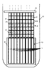
[0003] With reference to FIGURES 1 and 2, the lower portion of a nuclear power
plant
of the pressurized water configuration, commonly called a pressurized water
reactor
(PWR) design, is shown. A nuclear reactor core 10 comprises an assembly of
vertically
oriented fuel rods containing fissile material, typically 235U. The reactor
core 10 is
disposed at or near the bottom of a pressure vessel 12 that contains primary
coolant
water serving as a moderator to moderate the chain reaction and as coolant to
cool the
reactor core 10. The primary coolant further acts as a heat transfer medium
conveying
heat generated in the reactor core 10 to a steam generator. At the steam
generator, heat
from the primary coolant transfers to a secondary coolant loop to convert the
secondary
coolant into steam that is used for a useful purpose, such as driving a
turbine of an
electrical power generation facility. A conventional PWR design includes one
or (typically)
more steam generators that are external to the pressure vessel containing the
nuclear
reactor core. Large-diameter piping carries primary coolant from the pressure
vessel to
the external steam generator and back from the steam generator to the pressure
vessel
to complete a primary coolant flow loop. In some designs the external steam
generator is
replaced by an internal steam generator located inside the pressure vessel,
which has
the advantage of eliminating the large diameter piping (replaced by secondary
coolant
feedwater and steam outlet lines that are typically of lower diameter and that
do not carry
the primary coolant that flows through the reactor core). Note that FIGURE 1
is a
diagrammatic view of the lower reactor core region and does not include
features relating
to the steam generator or ancillary components.
[0004] The vertical fuel rods of the reactor core 10 are organized into fuel
assemblies
14. Illustrative FIGURE 1 shows a side view of a 9x9 array of fuel assemblies
14, although
arrays of other sizes and/or dimensions can be employed.
1
CA 2870613 2019-08-13
CA 02870613 2014-10-15
WO 2013/158711 PCT/US2013/036888
In turn, each fuel assembly 14 comprises an array of vertically oriented fuel
rods,
such as a 18x18 array of fuel rods, or a 14x14 array, or so forth. The fuel
assemblies
further include a lower end fitting, upper end fitting, vertical guide tubes
connecting
the end fittings, and a number of spacer grids connected to the guide tubes,
instrument tubes and fuel rods. The spacer grids fit around the guide tubes to
precisely define the spacing between fuel rods and to add stiffness to the
fuel
assembly 14. The spacer grids may or may not be welded to the guide tubes.
(Note,
FIGURES 1 and 2 represent the fuel rods of each fuel assembly 14 are shown
diagrammatically with vertical lines which are not to scale respective to size
or
quantity, and the spacer grids, guide tubes, and other features are not
shown). It is
noted that the dimensions of the array of fuel assemblies 14 may in general be
different from the dimensions of the array of fuel rods within the fuel
assembly 14.
The fuel assemblies may employ rectangular fuel rod packing and have a square
cross section, or may employ hexagonal fuel rod packing and have a hexagonal
cross section, or so forth). The reactor core 10 comprising fuel assemblies 14
is
disposed in a core basket 16 that is mounted inside the pressure vessel 12.
The
lower end fitting of each fuel assembly 14 includes features 18 that engage
with a
core plate. (The core plate, basket mounting, and other details are not shown
in
diagrammatic FIGURE 1).
[0005] The reactor control system typically includes a control rod assembly
(CRA)
operated by a control rod drive mechanism (CRDM) (not shown in FIGURES 1 and
2). The CRA includes vertically oriented control rods 20 containing neutron
poison. A
given control rod is controllably inserted into one fuel assembly 14 through a
designated vertical guide tube of the fuel assembly 14. Typically, all the
control rods
for a given fuel assembly 14 are connected at their top ends to a common
termination structure 22, sometimes called a spider, and a connecting rod 24
connects at its lower end with the spider 22 and at its upper portion with the
CRDM
(upper end not shown). The CRA for a single fuel assembly 14 thus comprises
the
control rods 20, the spider 22, and the connecting rod 24, and this CRA moves
as a
single translating unit. In the PWR design, the CRA is located above the
reactor core
and moves upward in order to withdraw the control rods 20 from the fuel
assembly 14 (and thereby increase reactivity) or downward in order to insert
the
control rods 20 into the fuel assembly 14 (and thereby decrease reactivity).
The
- 2 -
CA 02870613 2014-10-15
WO 2013/158711 PCT/US2013/036888
CRDM is typically designed to release the control rods so as to fall into the
reactor
core 10 and quickly quench the chain reaction in the event of a power failure
or other
abnormal event.
[0006] Because the reactor control system is a safety-related feature,
applicable
nuclear safety regulations (for example, promulgated by the Nuclear Regulatory
Commission, NRC, in the United States) pertain to its reliability, and
typically dictate
that the translation of the CRA be reliable and not prone to jamming. The
translation
of the CRA should be guided to ensure the control rods move vertically without
undue bowing or lateral motion. Toward this end, each CRA is supported by a
control rod guide structure 30 which comprises horizontal guide plates 32
mounted in
a spaced-apart fashion on vertical frame elements 34. Each guide plate 32
includes
openings or passages or other camming surfaces (not visible in the side view
of
diagrammatic FIGURES 1 and 2) that constrain the CRA so that the rods 20, 24
are
limited to vertical movement without bowing or lateral movement.
[0007] With continuing reference to FIGURES 1 and 2, the CRA guide assemblies
30 have substantial weight indicated by downward arrow FG,weight in FIGURE 2,
and
are supported by a weight-bearing upper core plate 40. The fuel assemblies 14
are
also relatively heavy. However, in a conventional PWR the primary coolant
circulation rises through the fuel assemblies 14, producing a net lifting
force on the
fuel assemblies 14 indicated by upward arrow FFA,lift= Accordingly, the fuel
assemblies 14 while typically resting on the bottom of the core basket 16, are
susceptible to being lifted upward by the lift force FFA,lift and press
against the upper
core plate 40. The lift force FFA,lift is thus also borne by the upper core
plate 40. The
upper core plate 40 thus is a spacer element disposed between and spacing
apart
the lower end of the CRA guide assembly 30 and the upper end of the
corresponding
fuel assembly 14. To avoid damaging the fuel rods, each fuel assembly 14
typically
includes a hold-down spring sub-assembly 42 that preloads the fuel assembly 14
against the upper core plate 40 and prevents lift-off of the fuel assembly 14
during
normal operation. The hold-down spring 42 is thus also disposed between the
lower
end of the CRA guide assembly 30 and the upper end of the corresponding fuel
assembly 14.. Additionally, alignment features 44, 46 are provided on the
upper end
of the fuel assembly 14 and the lower end of the CRA guide structure 30,
respectively, to assist alignment.
- 3 -
CA 02870613 2014-10-15
WO 2013/158711 PCT/US2013/036888
[0008] A PWR such as that of FIGURES 1 and 2 is typically designed to provide
electrical power of around 500-1600 megawatts. The fuel assemblies 14 for
these
reactors are typically between 12 and 14 feet long (i.e., vertical height) and
vary in
array size from 14x14 fuel rods per fuel assembly to 18x18 fuel rods per fuel
assembly. The fuel assemblies for such PWR systems are typically designed to
operate between 12- and 24-month cycles before being shuffled in the reactor
core.
The fuel assemblies are typically operated for three cycles before being moved
to a
spent fuel pool. The fuel rods typically comprise uranium dioxide (UO2)
pellets or
mixed UO2/gadolinium oxide (UO2-Gd203) pellets, of enrichment chosen based on
the desired core power.
BRIEF SUMMARY
[0009] In one aspect of the disclosure, a pressurized water reactor (PWR)
comprises: a pressure vessel containing primary coolant water; a nuclear
reactor
core disposed in the pressure vessel and including a plurality of fuel
assemblies
wherein each fuel assembly includes a plurality of fuel rods containing a
fissile
material; a control system including a plurality of control rod assemblies
wherein
each control rod assembly is guided by a corresponding control rod assembly
guide
structure; and a support element disposed above the control rod assembly guide
structures wherein the support element supports the control rod assembly guide
structures. In some embodiments the pressure vessel is a cylindrical pressure
vessel
and the support element comprises a support plate having a circular periphery
supported by the cylindrical pressure vessel. In some embodiments the control
rod
assembly guide structures hang downward from the support plate. In some
embodiments the lower end of each control rod assembly guide structure
includes
alignment features that engage corresponding alignment features of the upper
end of
the corresponding fuel assembly.
[0010] In another aspect of the disclosure, a method comprises: operating a
pressurized water reactor (PWR) wherein the operating includes circulating
primary
coolant in a pressure vessel upward through a nuclear reactor core that
includes a
plurality of fuel assemblies wherein each fuel assembly includes a plurality
of fuel
rods containing a fissile material; and during the operating, suspending
control rod
drive assembly guide structures disposed in the pressure vessel from
suspension
- 4 -
CA 02870613 2014-10-15
WO 2013/158711 PCT/US2013/036888
anchors disposed above the control rod drive assembly guide structures. In
some
such method embodiments, a downward force (other than gravity) is not applied
against the fuel assemblies during the operating. In some such method
embodiments, upward strain of the fuel assemblies and downward strain of the
suspended control rod drive assembly guide structures is accommodated during
the
operating by a gap between the tops of the fuel assemblies and the bottoms of
the
suspended control rod drive assembly guide structures.
[0011] In another aspect of the disclosure, a pressurized water reactor (PWR)
comprises: a pressure vessel containing primary coolant water; a nuclear
reactor
core disposed in the pressure vessel and including a plurality of fuel
assemblies
wherein each fuel assembly includes a plurality of fuel rods containing a
fissile
material; a control system including a plurality of control rod assemblies
wherein
each control rod assembly includes control rods selectively inserted into the
nuclear
reactor core and wherein each control rod assembly is guided by a
corresponding
control rod assembly guide structure; wherein there is a gap between the
bottoms of
the control rod assembly guide structures and the top of the nuclear reactor
core and
wherein no spacer element or spring is disposed in the gap. In some
embodiments
the control rod assembly guide structures are not supported from below the
control
rod assembly guide structures. In some embodiments there is a one-to-one
correspondence between the control rod assembly guide structures and the fuel
assemblies of the nuclear reactor core, and the lower end of each control rod
assembly guide structure includes alignment features that engage corresponding
alignment features of the upper end of the corresponding fuel assembly. In
some
embodiments the PWR further includes a support element disposed above the
control rod assembly guide structures and anchoring the tops of the control
rod
assembly guide structures such that the control rod assembly guide structures
are
suspended from the support element. In some embodiments flow of primary
coolant
water in the pressure vessel in the operational state of the PWR is not
sufficient to lift
the fuel assemblies upward.
[0012] In another aspect of the disclosure, a nuclear reactor fuel assembly is
configured for installation and use in a pressurized water nuclear reactor
(PWR). The
nuclear reactor fuel assembly includes a bundle of fuel rods containing a
fissile
material, and alignment features disposed at an upper end of the nuclear
reactor fuel
- 5 -
CA 02870613 2014-10-15
WO 2013/158711 PCT/US2013/036888
assembly. The upper end of the nuclear reactor fuel assembly is not configured
as a
load bearing structure. In some embodiments the upper end of the nuclear
reactor
fuel assembly does not include any hold-down springs. In some embodiments the
alignment features disposed at the upper end of the nuclear reactor fuel
assembly
are configured to mate with corresponding alignment features of a control rod
assembly guide structure.
BRIEF DESCRIPTION OF THE DRAWINGS
[0013] The invention may take form in various components and arrangements of
components, and in various process operations and arrangements of process
operations. The drawings are only for purposes of illustrating preferred
embodiments
and are not to be construed as limiting the invention.
[0014] FIGURE 1 diagrammatically shows a side sectional view of the lower
portion
of a pressurized water reactor (PWR) according the the prior art.
[0015] FIGURE 2 diagrammatically shows an exploded view of a single fuel
assembly and the corresponding control rod assembly (CRA) guide structure of
the
prior art PWR of FIGURE 1.
[0016] FIGURE 3 diagrammatically shows a side sectional view of the lower
portion
of a low flow rate PWR as disclosed herein.
[0017] FIGURE 4 diagrammatically shows an exploded view of a single fuel
assembly and the corresponding CRA guide structure of the disclosed PWR of
FIGURE 3.
[0018] FIGURE 5 diagrammatically shows an enlarged view of the lower end of
the
CRA guide structure and upper end of the fuel assembly of the embodiment of
FIGURES 3 and 4 showing the mating features and the gap.
[0019] FIGURE 6 diagrammatically shows a single fuel assembly and the
corresponding CRA guide structure of another disclosed PWR embodiment.
[0020] FIGURE 7 diagrammatically shows a suitable shipping configuration for
shipping the fuel assembly and continuous CRA guide structure via rail or
another
suitable carrier to a PWR site for installation during a fueling or refueling
operation.
- 6 -
CA 02870613 2014-10-15
WO 2013/158711 PCT/US2013/036888
DETAILED DESCRIPTION OF THE PREFERRED EMBODIMENTS
[0021] With reference to FIGURES 3 and 4, a pressurized water reactor (PWR) is
shown which is designed to operate as a small modular reactor (SMR). The SMR
preferably outputs 300 megawatts (electrical) or less, although it is
contemplated for
the SMR to output at higher power. The PWR of FIGURES 3 and 4 is designed to
operate at a relatively low primary coolant flow rate, which is feasible
because of the
relatively low SMR output power. The PWR of FIGURES 3 and 4 includes a number
of components that have counterparts in the PWR of FIGURES 1 and 2, including:
a
reactor pressure vessel 12; a reactor core 10 comprising fuel assemblies 14 in
a
core basket 16; a control rod assembly (CRA) for each fuel assembly that
includes
control rods 20 mounted on a spider 22 connected to the lower end of a
connecting
rod 24; and a CRA guide structure 30 for each CRA comprising horizontal guide
plates 32 mounted in a spaced-apart fashion on vertical frame elements 34.
Although these components have counterparts in the conventional PWR of
FIGURES 1 and 2, it is to be understood that the sizing or other aspects of
the
components in the PWR of FIGURES 3 and 4 may be optimized for the SMR
operational regime. For example, a PWR designed to operate at 150 megawatts
electrical may have fuel assemblies 14 that are 8 feet long and use a 17x17
bundle
of fuel rods per fuel assembly 14 with 24 guide tubes spaced on a 0.496-inch
pitch.
[0022] The PWR of FIGURES 3 and 4 omits the upper core plate 40 of the
embodiment of FIGURES 1 and 2. Omitting this weight-bearing plate 40 has
substantial advantages. It reduces the total amount of material thus lowering
manufacturing cost. Additionally, the upper core plate 40 presents substantial
frontal
area generating flow resistance. Although this can be mitigated to some extent
by
including flow passages in the plate 40, the frontal area occupied by the
control rods
20, the lower end plates of the CRA guide assemblies 30, and the upper end
fittings
of the fuel assemblies 14, limits the amount of remaining frontal area that
can be
removed. The load-bearing nature of the upper core plate 40 also limits the
amount
of material that can be safely removed to introduce flow passages through the
plate
40, since removing material to provide flow passages reduces the load-bearing
capacity of the plate 40.
[0023] However, omitting the load-bearing upper core plate 40 introduces
substantial new issues. In the embodiment of FIGURES 1 and 2, the plate 40
- 7 -
CA 02870613 2014-10-15
WO 2013/158711 PCT/US2013/036888
performs the functions of supporting the weight of the CRA guide assemblies 30
and
providing the upper stop against which the lift force FFA,lift on the fuel
assemblies 14
operates to stabilize the positions of the fuel assemblies 14. Moreover, the
upper
core plate 40 provides a common anchor point for aligning the fuel assemblies
14
with their respective CRA guide assemblies 30. These issues are addressed in
the
embodiment of FIGURES 3 and 4 as follows.
[0024] In the embodiment of FIGURES 3 and 4, the CRA guide assemblies 30 are
suspended from above by a support element 50 disposed above the CRA guide
assemblies 30. In embodiments in which the pressure vessel 12 is a cylindrical
pressure vessel (where it is to be understood that "cylindrical" in this
context allows
for some deviation from a mathematically perfect cylinder, for example to
allow for
tapering of the upper end of the pressure vessel 12, adding various vessel
penetrations or recesses, or so forth), the support element 50 is suitably a
support
plate 50 having a circular periphery supported by the cylindrical pressure
vessel (for
example supported by an annular ledge, or by welding the periphery of the
plate 50
to an inner cylindrical wall of the cylindrical pressure vessel, or so forth).
In some
embodiments the CRA guide assemblies 30 are not supported from below. This
arrangement is feasible because in the SMR design the reduced height of the
fuel
assemblies 14 reduces the requisite travel for the CRA and hence reduces the
requisite height for the CRA guide assemblies 30 in the SMR of FIGURES 3 and 4
as compared with the higher power PWR of FIGURES 1 and 2.
[0025] The support element 50 is located in a less congested area of the
pressure
vessel 12 as compared with the upper core plate 40 of the PWR of FIGURES 1 and
2. The area above the CRA support structures 30 includes the upper ends of the
CRA assemblies 30 and the connecting rods 24, but not the fuel assemblies.
Accordingly, there is more "unused" frontal area of the support plate 50,
which allows
for forming relatively more and/or larger flow passages into the support
element 50.
The support element 50 is also further away from the reactor core 10 than the
upper
core plate 40 of the PWR of FIGURES 1 and 2, which makes any spatial variation
in
the flow resistance that may be introduced by the frontage of the support
element 50
less problematic as compared with the upper core plate 40.
[0026] The load-bearing provided by the upper core plate 40 respective to the
upward lift force FFAtift is not needed in the SMR of FIGURES 3 and 4, because
the
- 8 -
flow rate sufficient to provide SMR output of 300 megawatts (electrical) is
generally not
sufficient to generate a lift force capable of overcoming the weight of the
fuel assemblies
14. Thus, in the SMR embodiment of FIGURES 3 and 4 the fuel assemblies 14 have
a
net force FFA,weight which is the weight of the fuel assembly 14 minus the
lifting force
generated by the relatively low primary coolant flow rate. As a consequence,
the fuel
assemblies 14 remain supported from below by the core basket 16 (or by a core
plate
component inside of or forming the bottom of the core basket 16). Thus, in the
embodiment of FIGURES 3 and 4 the upper end of the fuel assembly 14 is not
configured
as a load-bearing structure, and both the upper core plate 40 and the hold-
down springs
42 are omitted in the SMR embodiment of FIGURES 3 and 4.
[0027] With continuing reference to FIGURES 3 and 4 and with further reference
to
FIGURE 5, relative alignment between corresponding CRA guide structure 30 and
fuel
assembly 14 is achieved by engagement of mating features 60 on the top end of
the fuel
assembly 14 and corresponding mating features 62 on the bottom end of the CRA
guide
structure 30. The features 60, 62 ensure lateral alignment. In the
illustrative embodiment
the mating features 60 on the top of the fuel assembly 14 are protrusions,
e.g. pins, and
the mating features 62 on the bottom of the CRA guide structure 30 are mating
recesses;
however, other mating feature configurations are contemplated. In some
embodiments
the mating pins 60 on the top of the fuel assembly 14 also serve as anchor
points for
lifting the fuel assembly 14 out of the PWR during refueling or other
maintenance
operations, as described in Walton et al., "Nuclear Reactor Refueling Methods
and
Apparatuses", U.S. Serial No. 13/213,389 filed August 19, 2011.
[0028] With particular reference to FIGURES 4 and 5, vertical alignment is an
additional
issue. The fuel assembly 14 and the CRA guide structure 30 are subject to
respective
strains SG,thermai and SFA,thermai as the components 14, 30 increase from
ambient
temperature to operational temperature. In the embodiment of FIGURES 3-5, the
upper
end of the CRA guide structure 30 and the lower end of the fuel assembly 14
are both
anchored. Thus, the thermal expansion causes the upper end of the fuel
assembly 14
and the lower end of the CRA guide structure 30 to come closer together. This
is
accommodated by a gap G between the lower end of the CRA guide structure 30
and the
upper end of the corresponding fuel assembly 14.
9
CA 2870613 2019-08-13
CA 02870613 2014-10-15
WO 2013/158711 PCT/US2013/036888
The gap G is chosen to accommodate thermal expansion at least up to
temperatures
credibly expected to be attained during operation or credible malfunction
scenarios.
The mating features 60, 62 are designed to span the gap G in order to provide
the
lateral alignment between the CRA guide structure 30 and corresponding fuel
assembly 14. It will be noted that there is no spacer element or spring in the
gap G.
(The control rods 20 do pass through the gap G when inserted into the fuel
assembly
14; however, the control rods 20 are not spacer elements that space apart the
CRA
guide structure 30 and fuel assembly 14, and are also not springs. Similarly,
primary
coolant water fills the gap G but is also neither a spacer element nor a
spring).
[0029] The embodiment of FIGURES 3-5 employs the CRA guide structure 30
which comprises the spaced apart horizontal guide plates 32 mounted on the
vertical
frame elements 34. This is a conventional CRA guide structure design, and is
commonly used in conjunction with external control rod drive mechanism (CRDM)
units (not shown in FIGURES 3-5) disposed outside of and above the pressure
vessel 12 of the PWR. In some embodiments, it is contemplated to employ
internal
CRDM disposed inside the pressure vessel 12.
[0030] With reference to FIGURE 6, it is also contemplated to employ a
continuous
CRA guide structure 30C which provides continuous support/guidance of the CRA
over the entire length of the continuous CRA guide structure 30C. The
embodiment
of FIGURE 6 also employs a heavy terminating element 22H in place of the
conventional spider to provide the common termination structure at which the
top
ends of the control rods 20 are connected. The heavy terminating element 22H
advantageously adds substantial weight to the translating CRA 20, 22H, 24 as
compared with the conventional CRA 20, 22, 24 of the PWR of FIGURES 3-5. This
additional weight reduces SCRAM time and effectively compensates for the
otherwise reduced weight of the SMR CRA which is shortened as compared with
the
CRA of a higher-power PWR. The "Inset" of FIGURE 6 shows a perspective view of
the heavy terminal element 22H, while "Section A-A" of FIGURE 6 shows a
cross-section of the continuous CRA guide structure 30C. As seen in Section A-
A,
the CRA guide structure 30C includes camming surfaces 70 that guide the
control
rods 20, and a larger contoured central opening 72 that guides the heavy
terminal
element 22H. Additionally, the CRA guide structure 30C includes flow passages
74
to allow primary coolant water to egress from the internal volume 70, 72
quickly as
- 10 -
the CRA falls during a SCRAM. Additional aspects of the continuous CRA guide
structure
30C and the heavy terminal element 22H are set forth in Shargots et al.,
"Support
Structure For A Control Rod Assembly Of A Nuclear Reactor", U.S. Serial No.
12/909,252
filed October 21, 2010.
[0031] With reference to FIGURE 7, the fuel assembly 14, CRA guide structure
30C,
and connecting rod 24 are suitably shipped as components. Because the upper
end of
the nuclear reactor fuel assembly is not configured as a load-bearing
structure and does
not include the hold-down spring sub-assembly 42 (cf. FIGURE 2), shipping
weight is
reduced, and the possibility of collision or entanglement of the hold-down
springs with
surrounding objects during shipping is eliminated. As seen in FIGURE 7, the
shipping
configuration for the fuel assembly 14 includes the control rods 20 fully
inserted into the
fuel assembly 14.. Optionally, the heavy terminal element 22H (or,
alternatively, the spider
22 in embodiments employing it) is connected to the top ends of the control
rods 20 that
are inserted into the fuel assembly 14 during shipping. The continuous CRA
guide
structure 30C can be shipped as a single pre-assembled unit, as shown in
FIGURE 7, or
alternatively may be constructed as stacked segments that are shipped in
pieces and
welded together at the PWR site. The connecting rod 24 is suitably shipped as
a separate
element that is detached from the spider or heavy terminal element 22, 22H.
The lower
end of the connecting rod 24 optionally includes a J-lock fitting or other
coupling 80 via
which the lower end may be connected to the spider or heavy terminal element
22, 22H
during installation into the PWR. Alternatively, the lower end may be directly
welded to
the spider or heavy terminal element 22, 22H.
[0032] The preferred embodiments have been illustrated and described.
Obviously,
modifications and alterations will occur to others upon reading and
understanding the
preceding detailed description. It is intended that the invention be construed
as including
all such modifications and alterations insofar as they come within the scope
of the
appended claims or the equivalents thereof.
11
CA 2870613 2019-08-13