Note: Descriptions are shown in the official language in which they were submitted.
CA 02870647 2014-11-10
1
"A drive assembly for industrial machines"
DESCRIPTION
[0001] The present invention concerns a stepless speed
variation drive assembly, in particular for application
on industrial, agricultural or railway machinery.
[0002]This drive assembly allows the machine to cover a
wide speed range, without having to change gear. It
ensures that, without diskontinuity, the obtaining of
high torque at low speed, and high speed output when the
torque tractor requested is not high.
[0003] In various embodiments known from the state of the
art, the drive assembly comprises at least one input
pinion gear, an intermediate shaft and an output shaft,
which can be connected by means of universal joints, or
directly, to one or two further drive members (for
example, axles).
[0004]The assembly can be connected to two or more
hydraulic motors; of them, at least one motor transmits
the motion directly to the output shaft and is therefore
always engaged, and at least one motor is connectable to
and releasable from the output shaft through a clutch,
for example a multi-disk clutch, operated by a piston.
[0005] Thanks to the presence of the clutch, it is possible
the disengagement of the hydraulic motor, which can then
be exploited at low speed to deliver more torque, and can
CA 02870647 2014-11-10
2
be switched off at higher speeds when the torque of the
engine is no longer necessary .
[0006] Such a drive assembly, however, suffers
the
inconvenience that, when the clutch is released to
decouple the motor from the output shaft, the engine
disconnected can continue, however, by inertia, to be
driven in rotation, with consequent power absorption and
of efficiency decay of the drive or, worse, with the risk
of its consequent damage (if for effect of dragging it
W were to rotate at speeds higher than those allowed by its
manufacturer).
WTI Also from the state of the art an alternative
embodiment is known, which tries to eliminate this
disadvantage by combining a brake to the disengagement
device of one of the hydraulic motors, in order to
prevent that the hydraulic motor can be driven in
rotation once switched off.
[0008] However, even this alternative embodiment has
technical limitations, which may affect the actual use
successfully in applications with rather high installed
power.
[0009] In particular, this embodiment provides that both
the engagement/disengagement device of one of the
hydraulic motors, and the corresponding brake, are
realized by means of conical synchronizers with an
81783764
3
optional subsequent additional coupling to the teeth,
where it is necessary to transmit high torques.
[00101The conical synchronizers,
however, are
characterized by limited energy absorption capacity,
limited thermal capacity and consequently limited ability
to synchronize high speed differences or to allow
repeated insertion under load. Sometimes, in order not to
burn, they require an additional synchronization of the
speeds, obtained by controlling appropriately the
variation of the hydraulic motors size, and that involves
a complication in the control electronics of the system.
[0011] Finally, the embodiment based on
conical
synchronizers explicitly provides for the use, for the
control of the clutch-brake system, _of an appropriate
external actuator, with a spring system, which is
necessary to be able to control a gradual insertion of
the synchronizers themselves.
[0012] The object of the present invention is to provide a
drive assembly of the abovementioned type, but free from
said disadvantages, and at the same time of high
reliability and compactness of dimensions.
Date Recue/Date Received 2021-02-02
81783764
3a
[0013] In some embodiments disclosed herein, there is provided
a stepless speed variation transmission drive unit, in
particular for industrial, agricultural or railway machinery,
comprising at least a first input pinion, at least a first
hydraulic motor connected to said first input pinion, an output
shaft, and at least a second hydraulic motor, wherein the first
hydraulic motor is selectively connectable and disconnectable
to/from said output shaft by means of a multi-disc clutch,
wherein the second hydraulic motor is adapted to transmit the
movement directly to the output shaft, wherein the transmission
drive unit further comprises a multi-disc brake device adapted
to block the rotation of the first hydraulic motor when said
first hydraulic motor is disconnected from the output shaft, an
intermediate shaft between said input pinion and said output
shaft, wherein the first input pinion is adapted to transmit
the movement to the output shaft by means of said intermediate
shaft, and wherein the intermediate shaft is connected and
disconnected from said output shaft by means of said multi-disc
clutch, wherein the clutch comprises a pack of discs coated
with friction material interposed to a pack of metal counter-
discs, the pack of discs being operatively connected in
rotation to the output shaft, the pack of counter-discs being
integral with the intermediate shaft, or vice versa, and
wherein said clutch is controlled by a clutch actuator operated
to make the pack of discs integral with the pack of counter-
discs, wherein said clutch actuator is of the hydraulically or
pneumatically-operated type, and wherein said clutch actuator
comprises a piston-cylinder system, wherein the piston is
composed of a flange made on the intermediate shaft, and
wherein the cylinder is sealingly assembled around said flange
Date Recue/Date Received 2021-02-02
81783764
3b
so as to define therewith a front cylinder chamber and a rear
cylinder chamber, said front and rear chambers being supplied
alternately by a pressurised fluid so as to command the
cylinder to translate axially between an advanced position of
compression of the packs of discs and counter-discs and a
rearward disengaged position of the discs from the counter-
discs.
[0014] In some embodiments disclosed herein, the drive assembly
Date Recue/Date Received 2021-02-02
CA 02870647 2014-11-10
4
according to the invention comprises at least a first
input pinion, at least a first hydraulic motor connected
to said first input pinion, an output shaft, and at least
a second hydraulic motor . The first hydraulic motor is
connectable to, and releasable from said output shaft by
means of a multidisk clutch; the second hydraulic motor
is suitable to transmit the motion directly to the output
shaft.
[0015]The drive assembly further comprises a multidisk
brake device, suitable to block the rotation of the first
hydraulic motor when said first hydraulic motor is
released from the output shaft.
[0016] Therefore, the hydraulic motor (or hydraulic motors,
if more than one) that is switched off, is then braked to
exclude the possibility that it is driven in rotation,
with consequent worsening of the efficiency of the drive
and the possibility of damage to the engine itself .
[0017]The use of a multidisk clutch and a multidisk brake
also (characterized by high thermal capacity), in place
of conical synchronizers, allows to increase
significantly the capacity of insertion under load, and
also allows a reduction of the interval of time required
for the insertion (as the synchronization of the speeds
is much faster and more accurate), and avoids the need of
a dedicated electronic control system for controlling the
CA 02870647 2014-11-10
displacements of the hydraulic motors.
WM In an advantageous embodiment, the first input
pinion is suitable to transmit motion to the output shaft
through an intermediate shaft, the multidisk clutch being
5 adapted to connect and release said intermediate shaft to
the output shaft.
[0019]Advantageously, the brake device acts on the
rotation of the intermediate shaft.
[0020]Advantageously, moreover, the clutch and the brake
device are driven by a same clutch-brake actuator. In one
embodiment, this clutch-brake actuator is integrated
within the drive assembly.
[0021] In one embodiment, at least one second hydraulic
motor is connected to a second input pinion suitable to
transmit the motion directly to the output shaft.
[0022]The features and advantages of the drive assembly
according to the invention will anyhow be evident from
the following description of its preferred embodiments,
given by way of non-limiting example, with reference to
the accompanying drawings, in which:
[0023]- Figure 1 is a diagram of a drive assembly
according to the invention, in a preferred embodiment;
[0024]- figure 2 shows, in section, an embodiment of a
clutch-brake actuator for the drive assembly of Figure 1;
[0025]- Figure 3 is a diagram of a drive assembly
CA 02870647 2014-11-10
6
according to ab embodiment variation of the invention;
and
[00261- Figure 4 illustrates schematically the drive
assembly of Figures 1 and 2 including a housing
containing and supporting the functional components of
the assembly.
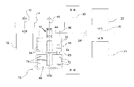
[0027]In a preferred embodiment illustrated in Figure 1,
the drive assembly, indicated by 1 in its entirety,
comprises at least one first input pinion 10, a second
input pinion 20, an output shaft 30, and a intermediate
shaft 40 between said first input pinion 10 and said
output shaft 30.
[0028] The output shaft 30 can be connected by universal
joints, or directly, to one or two further drive members,
for example to axles.
[0029] At least one first hydraulic motor 12 is connected
to the first input pinion 10. One or more hydraulic
motors 22, 23 are connected to the second input pinion
20. In an alternative embodiment, these second hydraulic
motors may be directly connected to the intermediate
shaft 40 or directly connected to the output shaft 30, so
that the second input pinion 20 and possibly also the
intermediate shaft 40 may also be unnecessary.
[0030] Returning to the preferred embodiment of Figure 1,
the first input pinion 10 transmits the motion to the
CA 02870647 2014-11-10
7
output shaft 30 through the intermediate shaft 40.
[0031] In one embodiment, the first input pinion 10 is
suitable to transmit the motion to the intermediate shaft
40 through a first toothed gear 14. The second input
pinion 20 is suitable to transmit the motion directly to
the shaft output 30, for example through a second toothed
gear 24, and is therefore always engaged.
[0032] In one embodiment, the intermediate shaft 40
supports, for example by a system of bearings 42, an
intermediate gear 44 rotatably connected to the
Intermediate shaft, for example by means of a third
toothed gear 46.
[0033] The intermediate shaft 40 is connectable to and
releasable from the output shaft 30 by means of a
multidisk clutch 50.
[0034] In a preferred embodiment, the clutch 50 is a
multidisk clutch comprising a disk pack 52 covered in
friction material interposed to a pack of metal counter
disks 54. The disk pack 52 is operatively connected in
rotation, for example via the intermediate gear 44 and
the third toothed gear 46, to the output shaft 30; the
pack of counter disks 54 is integral with the
intermediate shaft 40, or vice versa. For example, the
disk pack 52 is radially constrained to the intermediate
44, while the pack of counter disks 54 is radially
CA 02870647 2014-11-10
8
constrained to the intermediate shaft 40.
[0035] When the two packs of disks and counter disks 52,
54 are pressed each other, the resulting friction makes
the intermediate gear 44 integral to the intermediate
shaft 40, so that the driving torque from the first
pinion 10 can be transmitted to the output shaft 30
through the third toothed gear 46. When instead the packs
of disks and counter disks 52, 54 are not placed in
mutual compression, the intermediate gear 44 can rotate
freely with respect to the intermediate shaft 40, being
supported by the bearing system 42, and therefore allows
to decouple from the output shaft 30 both the
intermediate shaft 40 and the first input pinion 10.
[0036] In a preferred embodiment, the multidisk clutch 50
is controlled by a clutch actuator 60 operable to make
the disk pack 52 integral with to the pack of counter
plates 54.
[0037] In one embodiment, the clutch actuator 60 is made
with a piston-cylinder system 401, 402, pneumatically,
hydraulically or mechanically operated.
[0038] More in detail, and with reference to Figure 2,
the piston is formed by a flange 401 formed on the
intermediate shaft 40, and the cylinder 402 is sealably
assembled around said flange 401 so as to define with
said flange 401 a front cylinder chamber 403 and a rear
CA 02870647 2014-11-10
9
cylinder chamber 404. These front and rear chambers 403,
404 are alternately powered by a pressurized fluid so as
to control the cylinder 402 to translate axially between
an advanced position of compression of the packs of disks
52 and counter disks 54 and a retracted position of
disengagement of the disks 52 from the counter disks 54.
For example, the pressurized fluid is fed to the cylinder
chambers through air passage holes or oil passage hole
drilled in the intermediate shaft 40.
[0039] In accordance with a general aspect of the
invention, the drive assembly 1 also comprises a
multidisk brake device 70 suitable to block the rotation
of the first hydraulic motor 12 when this is released
from the output shaft 30.
[0040] In the illustrated example, the brake device 70
stops the rotation of the first input pinion 10,
preferably by acting on the rotation of the intermediate
shaft 40.
[0041] In a preferred embodiment illustrated in Figures 1
and 2, the multidisk clutch 50 and the multidisk brake
device 70 are driven by a same actuator clutch-brake 60,
preferably integrated in the drive assembly. More in
detail, said clutch-brake actuator is movable between a
first brake position, in which actuates the brake device
70 and at the same time is disengaged from the clutch 50,
CA 02870647 2014-11-10
and a second clutch position, in which releases the brake
device 70 and simultaneously actuates the clutch 50 to
connect in rotation the intermediate shaft 40 to the
output shaft 30.
5 [0042] Preferably, therefore, the multidisk brake device
70 acts on the rotation of the intermediate shaft 40.
[0043] For example, the multidisk brake device 70 is
actuated by the cylinder of the clutch actuator 60.
[0044] More in detail, the multidisk brake device 70
10 comprises a pack of brake disks 74 covered by a friction
material, interposed to a pack of brake metal counter
disks 72. The brake disks 74 are pressed against the
brake counter disks 72 from the cylinder of the clutch
actuator 60 when said cylinder is in the retracted
position.
[0045] In one embodiment, the pack of brake counter disks
72 is integral radially to the intermediate shaft 40,
while the pack of brake disks 74 is radially integral
with a static part of the drive assembly, for example, to
a housing 80, or vice versa.
[0046] Therefore, when the clutch 50 is opened, the brake
counter disks 72 and the brake disks 74 are pressed each
other by the actuator clutch-brake 60, and the resulting
friction between them allows to make the static part 80
of the assembly drive integral with the intermediate
CA 02870647 2014-11-10
11
shaft 40.
[0047] Consequently to this, the intermediate shaft 40 is
stationary during rotation of the output shaft 30, and
the first input pinion 10 is also stationary, as the
hydraulic motor 22 connected to it. It becomes impossible
for the hydraulic motor 12 to be unintentionally driven
rotating when switched off.
[0048] Advantageously, the fact that the first hydraulic
motor 12 connected to the first pinion 10 is not rotated
when disengaged allows to avoid its power absorption
(which, although limited, would deteriorate the
efficiency of the drive) and to prevent that the motor,
driven in rotation at high speed, can be damaged.
[0049] In a variant embodiment illustrated in Figure 3,
where the elements common to those described with
reference to Figure I are indicated by the same reference
numerals, the multidisk brake device 70 can be applied to
the first input pinion 10, rather than the intermediate
shaft 40.
[0050] For example, the pack of brake counter disks 72
may be radially constrained to the first pinion 10, while
the pack of brake disks 74 may be radially constrained to
a static part 80 of the drive assembly, for example the
casing.
[0051] The brake device 70, in this embodiment, can be
CA 02870647 2014-11-10
12
operated by its own brake actuator 90.
[0052] In a preferred embodiment illustrated in Figure 4,
the drive assembly comprises a casing 80 containing and
supporting at least the first input pinion 10, the output
shaft 30, the multidisk clutch 50, the multidisk brake
70, the actuator brake-clutch 60 and, if present, the
intermediate shaft 40 and the second input pinion 20.
Advantageously, therefore, the actuator brake-clutch 60
is housed inside the casing 80 of the drive assembly.
[0053] To the embodiments of the drive assembly according
to the invention one skilled in the art, in order to
satisfy contingent needs, may make modifications,
adaptations and replacements of elements with other
functionally equivalent, without departing from the scope
of the following claims. Each of the characteristics
described as belonging to a possible embodiment can be
obtained independently from other embodiments described.