Note: Descriptions are shown in the official language in which they were submitted.
CA 02870717 2014-10-16
WO 2013/187855
PCT/US2012/041807
INITIATOR DEVICE FOR A DOWNHOLE TOOL
CROSS-REFERENCE TO RELATED APPLICATIONS
[0001] Not applicable.
FIELD
[0002] The present invention generally relates to means of initiating downhole
tools
that are used in a subterranean well.
BACKGROUND
[0003] Autonomous downhole tools used in subterranean wells are frequently
programmed using a surface system computer prior to being integrated into a
tool string
and sent downhole. The surface system can initiate processes in the tool, for
example the
initiation of a countdown, in which operations of the tools begin after a time
delay.
However, communication between the surface system and the tool is often not
possible
during a period of time prior to integration and until after the tool is
lowered into the
hole. Certain tools, such as tubing conveyed, slick-line, logging while
drilling (LWD),
and measurement while drilling (MWD) tools may not have a wired connection to
the
surface system and can only be communicated to through mud pulse telemetry,
which
may not be possible until the tool is sufficiently integrated into the
downhole tool
assembly. In some cases, no communication between the surface system and the
tool is
possible during the entire job while the tool is integrated in the downhole
assembly.
1
CA 02870717 2014-10-16
WO 2013/187855
PCT/US2012/041807
[0004] Once
the programming is initiated, tools that do not have a connection to the
surface may be expected to run autonomously for a duration of the job or for
the entire
job. At times it is desirable to have one or more processes within the tool
start at a
specified time prior to integrating the tool into the tool string without the
use of a surface
system. For instance, the surface system may be located far from the area of
tool string
integration, yet it is not desirable to initiate a process in the tool until
the tool has been
moved into the integration area. Furthermore, the time between removing the
tool from
the surface system and integrating the tool into the tool string may not be
known in
advance. In cases where the initiation of a process in a tool begins a
countdown, it is
desirable to be able to initiate the process at a chosen time prior to tool
string integration.
[0005]
Initiating a process within a downhole tool often involves using a power
source, such as a surface system computer. Often, weather conditions and/or
the safety
risks associated with certain oil field rig zone areas, such as Zone 2 rig
environments, can
make the use of electric power sources dangerous. In such cases, it is
desirable to initiate
a process in a downhole tool without the use of electrical power.
[0006] When
downhole tools are initiated using a surface system, it can be difficult to
determine whether initiation was successful. Some tools produce a faint sound
or
vibration to indicate that a process has been initiated, which indications may
be difficult
for workers to detect in muddy, rainy, and/or noisy oil field environments.
[0007] A need
exists for a simple means of initiating a process in an autonomous
downhole tool that addresses the issues discussed above.
2
CA 02870717 2014-10-16
WO 2013/187855
PCT/US2012/041807
BRIEF DESCRIPTION OF DRAWINGS
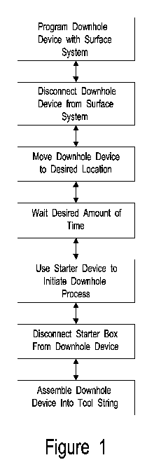
[0008] Figure 1 is a chart of an example job flow for initiating a process
in a
downhole tool.
[0009] Figure 2a ¨ b shows two examples of the initiator device's
configuration.
DETAILED DESCRIPTION
[0010] The invention includes a method of initiating a process in a
downhole tool and
for an initiator device.
[0011] In an embodiment, the invention is a method of initiating a process
in a
downhole tool. Specifically, the invention is for initiating a process in a
downhole tool,
while the tool is located at the surface, after a tool has been disconnected
from a surface
system but prior to its deployment and/or integration into a tool string. The
process to be
initiated can be any process for which the tool has been preprogrammed, such
as the start
of a countdown. "Initiation" is to be understood as distinct from the
"activation" or
"setting" of a downhole tool, wherein the tool begins to perform its primary
operation.
For example, in a perforating gun, initiation may refer to the initiation of a
process
according to the gun's computer programming, while activation may refer to
performing
the perforation.
[0012] The method of initiating a process in a downhole tool includes
creating a
loopback and/or loaded condition across signal lines in an initiator device
and detecting
the condition to initiate a process according to the tools' programming. The
method can
further include indicating successful initiation with an indicator on the
initiator device.
[0013] Figure 1 is a chart of an example job flow, describing the steps of
initiating a
process in a downhole tool. The downhole tool is connected to the surface
system and
programmed with job specific parameters. Upon completion of programming, the
tool is
disconnected from the surface system and moved to the integration area. The
tool
3
CA 02870717 2014-10-16
WO 2013/187855
PCT/US2012/041807
remains in the integration area until the rig crew is ready to integrate it
into the tool
string. Just prior to integration, the rig crew connects the initiator device
to the tool and
actuates the actuator according to a predetermined sequence. Once the device
indicates
the tool process has been successfully initiated, the crew disconnects the
device from the
tool and proceeds with integrating the tool into the tool string.
[0014] In an
embodiment, the invention is for an initiator device to be used with a
downhole tool. The initiator device includes wires that are capable of
connecting to the
tool signal lines. A downhole tool can be preprogrammed to constantly send out
a signal.
When the wires in the initiator devices are connected, and once a closed
circuit is created,
the signals travel across the wires of the initiator device and return to the
downhole tool.
The closed connection can create a loopback condition and/or a loaded
condition, which
can initiate a process in the tool according to the tool's programming. For a
loaded
condition, the signal lines of the initiator device may include load impedance
made up of
a combination of resistive and/or reactive components. The load impedance can
be made
up of discrete components and/or distributed components. For instance, the
load can be a
potentiometer.
[0015] In an
embodiment, the initiator device also includes an actuator. When
actuated, the actuator creates a closed connection between the wires and
permits the
receiving and transmitting of signals. The actuator can be a switch, and can
be any type
of switch, including sliding switches, button switches, toggle switches,
membrane
switches, slider switches, keypad switches, wheel switch, lever switches, and
the like.
[0016] In an
embodiment, the initiator device does not include an actuator. The
loopback and/or loaded condition is always set or hardwired.
[0017] In an
embodiment, the initiator device further includes an indicator, which can
indicate successful initiation of the tool. The indicator can be connected to
the transmit
line(s) of the tool during a loopback or load state. The indicator can employ
visual,
motion, and/or sound indication to communicate the state of the tool. The
indicator can
be chosen from digital displays, LEDs, buzzers, speakers, vibration motors,
and the like.
4
CA 02870717 2014-10-16
WO 2013/187855
PCT/US2012/041807
For example, an LED may be connected to the tool transmit line(s), and the
rate at which
the LED blinks is set by the characteristics of the signal being looped back.
For instance,
the connection may start with a slow blinking of the LED light, which can
increase in
frequency to a rapid blink once the tool communicates successful initiation of
the desired
process in the tool.
[0018] In an
embodiment, the initiator device does not contain any power source.
Often, weather conditions and/or the safety risks associated with certain oil
field rig zone
areas, such as Zone 2 rig environments, can make the use of power sources
dangerous. In
such cases, it is desirable to initiate a process in a downhole tool without
the use of
electrical power that could possibly be an ignition source.
[0019] Figure
2 is a diagram showing two possible embodiments, configurations A
and B, of the initiator device and the downhole tool. The downhole tool (1)
has, at
minimum, a connection to the communication signals used by the surface system
to
program the tool. Other signals may be provided by the tool and may or may not
be used
by the initiator device. In configuration A, the transmit (5) and receive (6)
signals are
communicated over the same signal lines, and a loopback scheme (9) is used
within the
initiator device (2). A loopback condition is created by actuating the
actuator (4) on the
initiator device (2) in a predetermined sequence. The indicator (11) will
change states
based on the state of the downhole tool. The ground return (7) may or may not
be used
for the loopback scheme.
[0020]
Configuration B shows the case where receive and transmit signals are
communicated over the same signal line (8). A predetermined load (10), made of
resistive and reactive components in a discrete or distributed manner, is
applied between
the signal line (8) and ground return (7) by actuating the actuator (4) in a
predetermined
sequence. The indicator (11), will change states based on the state of the
downhole tool.
[0021] The
loaded line (10) scheme can also be applied to the separate transmit line
(5) of Configuration A in combination with the loopback scheme (9) or as a
standalone
approach.
CA 02870717 2014-10-16
WO 2013/187855
PCT/US2012/041807
[0022] The
initiator device can be used in any known drilling environment, and is
especially useful in drilling environments that include extreme forms of
weather or that
have safety risks associated with certain oil field rig zone areas, such as
Zone 2 rig
environments.
[0023] The
initiator device can be used with any known downhole tool, including by
non-limiting examples: perforating guns, MWD and LWD tools.
[0024] While
compositions and methods are described in terms of "comprising,"
"containing," or "including" various components or steps, the compositions and
methods
can also "consist essentially of' or "consist of' the various components and
steps. Use of
the term "optionally" with respect to any element of a claim is intended to
mean that the
subject element is required, or alternatively, is not required. Both
alternatives are
intended to be within the scope of the claim.
[0025] All
numbers and ranges disclosed above may vary by some amount.
Whenever a numerical range with a lower limit and an upper limit is disclosed,
any
number and any included range falling within the range is specifically
disclosed. In
particular, every range of values (of the form, "from about a to about b," or,
equivalently,
"from approximately a to b," or, equivalently, "from approximately a-b")
disclosed
herein is to be understood to set forth every number and range encompassed
within the
broader range of values. Also, the terms in the claims have their plain,
ordinary meaning
unless otherwise explicitly and clearly defined by the patentee.
[0026]
Depending on the context, all references herein to the "invention" may in
some cases refer to certain specific embodiments only. In other cases it may
refer to
subject matter recited in one or more, but not necessarily all, of the claims.
While the
foregoing is directed to embodiments, versions and examples of the present
invention,
which are included to enable a person of ordinary skill in the art to make and
use the
inventions when the information in this patent is combined with available
information
and technology, the inventions are not limited to only these particular
embodiments,
versions and examples. Other and further embodiments, versions and examples of
the
6
CA 02870717 2014-10-16
WO 2013/187855
PCT/US2012/041807
invention may be devised without departing from the basic scope thereof and
the scope
thereof is determined by the claims that follow.
7